EP4542609A2 - Verbesserungen an oder im zusammenhang mit schnittstellenerkennung - Google Patents
Verbesserungen an oder im zusammenhang mit schnittstellenerkennung Download PDFInfo
- Publication number
- EP4542609A2 EP4542609A2 EP25154485.4A EP25154485A EP4542609A2 EP 4542609 A2 EP4542609 A2 EP 4542609A2 EP 25154485 A EP25154485 A EP 25154485A EP 4542609 A2 EP4542609 A2 EP 4542609A2
- Authority
- EP
- European Patent Office
- Prior art keywords
- sensor
- level switch
- switch
- section
- frequency
- Prior art date
- Legal status (The legal status is an assumption and is not a legal conclusion. Google has not performed a legal analysis and makes no representation as to the accuracy of the status listed.)
- Pending
Links
Images


Classifications
-
- G—PHYSICS
- G01—MEASURING; TESTING
- G01F—MEASURING VOLUME, VOLUME FLOW, MASS FLOW OR LIQUID LEVEL; METERING BY VOLUME
- G01F23/00—Indicating or measuring liquid level or level of fluent solid material, e.g. indicating in terms of volume or indicating by means of an alarm
- G01F23/22—Indicating or measuring liquid level or level of fluent solid material, e.g. indicating in terms of volume or indicating by means of an alarm by measuring physical variables, other than linear dimensions, pressure or weight, dependent on the level to be measured, e.g. by difference of heat transfer of steam or water
- G01F23/28—Indicating or measuring liquid level or level of fluent solid material, e.g. indicating in terms of volume or indicating by means of an alarm by measuring physical variables, other than linear dimensions, pressure or weight, dependent on the level to be measured, e.g. by difference of heat transfer of steam or water by measuring the variations of parameters of electromagnetic or acoustic waves applied directly to the liquid or fluent solid material
- G01F23/284—Electromagnetic waves
- G01F23/2845—Electromagnetic waves for discrete levels
-
- G—PHYSICS
- G01—MEASURING; TESTING
- G01F—MEASURING VOLUME, VOLUME FLOW, MASS FLOW OR LIQUID LEVEL; METERING BY VOLUME
- G01F23/00—Indicating or measuring liquid level or level of fluent solid material, e.g. indicating in terms of volume or indicating by means of an alarm
- G01F23/22—Indicating or measuring liquid level or level of fluent solid material, e.g. indicating in terms of volume or indicating by means of an alarm by measuring physical variables, other than linear dimensions, pressure or weight, dependent on the level to be measured, e.g. by difference of heat transfer of steam or water
- G01F23/28—Indicating or measuring liquid level or level of fluent solid material, e.g. indicating in terms of volume or indicating by means of an alarm by measuring physical variables, other than linear dimensions, pressure or weight, dependent on the level to be measured, e.g. by difference of heat transfer of steam or water by measuring the variations of parameters of electromagnetic or acoustic waves applied directly to the liquid or fluent solid material
- G01F23/284—Electromagnetic waves
Definitions
- This invention relates to interface detection and, in particular, to a microwave-based switch for use in industrial interface detection including, but not necessarily limited to, liquid-gas (air), liquid-liquid, solid-gas (air), and solid-solid interface detection.
- a further alternative form of interface for level detection has been proposed in the form of a microwave probe as described in US Patent 5,675,259 .
- the described probe comprises first and second electrodes in concentric relationship and electrically insulated from one another, an end of the probe being exposed to the media being sensed.
- Radio frequency signals are transmitted to the probe and phase and amplitude differences associated with the signals reflected from the open end of the probe in contact with the media are analysed to identify the media based on its complex permittivity.
- the invention provides a level switch operable to initiate a switching function in the event of a change of medium in contact with said switch, said switch including a sensor operable to sense a change of medium in contact with said switch, and drive and processing electronics configured and operable to provide drive signals to said sensor, to receive and process received signals from said sensor, and to initiate a switching function dependent on an amplitude and/or phase difference in frequency of said received signals, wherein said sensor comprises an open ended microwave waveguide formed by an outer electrode and an inner electrode held within said outer electrode with an electrical insulator there-between, said sensor having a connection end for connection to said drive and processing electronics, a distal end for contact with said medium, and a length L wherein said sensor is configured to create an impedance mismatch at or adjacent to said connection end.
- said sensor has a main waveguide section of impedance Z and wherein said impedance mismatch comprises a reflection section configured to have an impedance of greater than 1.5Z.
- said reflection section is configured to have an impedance of substantially 4Z.
- said reflection section comprises a cavity which is evacuated, or filled with air or a low permittivity foamed material.
- said sensor is configured to operate within a selected frequency band having a substantially central frequency f 0 with a wavelength ⁇ and wherein said impedance mismatch has a dimension in the direction of length L of a multiple of substantially 1 ⁇ 4 ⁇ .
- said main waveguide section has a dimension in the direction of L which is a multiple of 1 ⁇ 2 ⁇ .
- said sensor further includes a pressure resisting section extending between said inner and outer electrodes, said pressure resisting section having a dimension in the direction of L which is a multiple of 1 ⁇ 2 ⁇ .
- said pressure resisting section is positioned within the length of said main waveguide section.
- the distance between an edge of said pressure resistant section and an end of said main waveguide section is a multiple of 1 ⁇ 2 ⁇ .
- an expansion section is formed at said distal end in which said inner electrode is expanded in diameter and said outer electrode is reduced in thickness to accommodate the expansion.
- the dimension of said expansion section in the direction of L is a multiple of 1 ⁇ 2 ⁇ .
- said inner electrode projects beyond said outer electrode in the direction of L by an amount of the order of 1 10 ⁇ .
- an insulating coating is provided over said distal end to prevent short-circuiting between said inner and outer electrodes.
- said outer electrode and said inner electrode are substantially co-axial.
- processing electronics is configured to reduce the frequencies of said received signals before processing into a determination of a switching point.
- the invention provides a level switch operable to initiate a switching function in the event of a change of medium in contact with said switch, said switch including a sensor operable to sense a change of medium in contact with said switch, and drive and processing electronics configured and operable to provide drive signals to said sensor, to receive and process received signals from said sensor, and to initiate a switching function dependent on an amplitude and/or phase difference in frequency of said received signals, wherein said sensor comprises an open ended microwave waveguide formed by an outer electrode and an inner electrode held within said outer electrode with an electrical insulator there-between, said sensor having a connection end for connection to said processing electronics, a distal end for contact with a medium, and a length L and wherein said sensor is configured to operate within a frequency band having a frequency f 0 with wavelength ⁇ located substantially centrally within said band, said sensor including at least one impedance mismatch having a dimension in the direction of length L related to ⁇ .
- the invention provides a level switch operable to initiate a switching function in the event of a change of medium at a level of said switch, said switch including a sensor operable to sense a change of medium at a level of said switch, and drive and processing electronics configured and operable to provide drive signals to said sensor, to receive and process received signals from said sensor, and to initiate a switching function dependent on an amplitude and/or phase difference in frequency of said received signals, wherein said sensor comprises an open ended microwave waveguide formed by an outer electrode and an inner electrode held within said outer electrode with an electrical insulator there-between, said sensor having a connection end for connection to said drive and processing electronics, a distal end for mounting in substantial contact with a wall of a non-conductive vessel containing said medium or in conduct with a non-conductive window provided in a wall of a vessel containing said medium, said sensor having a length L wherein said sensor is configured to create an impedance mismatch at or adjacent to said connection end.
- the invention provides a level switch operable to initiate a switching function in the event of a change of medium at a level of said switch, said switch including a sensor operable to sense a change of medium at a level of said switch, and drive and processing electronics configured and operable to provide drive signals to said sensor, to receive and process received signals from said sensor, and to initiate a switching function dependent on an amplitude and/or phase difference in frequency of said received signals, wherein said sensor comprises an open ended microwavewaveguide formed by an outer electrode and an inner electrode held within said outer electrode with an electrical insulator there-between, said sensor having a connection end for connection to said processing electronics, and a distal end for mounting in substantial contact with a wall of a non-conductive vessel containing said medium or in conduct with a non-conductive window provided in a wall of a vessel containing said medium, said sensor having a length L and wherein said sensor is configured to operate within a frequency band having a frequency f 0 with wavelength ⁇ located substantially centrally within said band, said sensor including
- a typical prior art open-ended waveguide sensor 10 is shown in Figure 1 but reference can also be made to US Patent 5,675,259 which contains a detailed description of the construction and operation of such a sensor as well as various industrial applications in which a sensor of this type can be used.
- the sensor 10 has a connection end 11 and a distal end 12 for contact with a fluid which, in the context of this disclosure, includes gases, liquids and fine solids such as powders.
- the sensor 10 includes an inner electrode 13, an outer electrode 14, the electrodes 13 and 14 held in spaced relationship (typically co-axial relationship) by an electrically insulating material 15.
- the electrodes are typically formed from a metal such as stainless steel and the insulating material 15 may comprise a suitable plastics material such as polytetrafluoroethylene (PTFE), or a suitable ceramic.
- PTFE polytetrafluoroethylene
- the outer electrode 14 may comprise the outer body of the sensor which, in the form shown, includes a threaded section 16 to allow the sensor to be mounted in the position in which it is to be used. Typically this will be an aperture of a relatively restricted diameter in the wall of a process vessel.
- the sensor shown in Fig 1 is configured according to design rules which dictate that the impedance of the sensor should be kept as constant as possible along its length and that the sensor should operate over a wide frequency band with the highest possible cut-off frequency; that is to say the highest frequency to maintain transverse electromagnetic (TEM) mode.
- TEM transverse electromagnetic
- an open-ended wave-guide sensor 20 incorporated in a level switch according to the invention is configured to different design rules, namely:
- the sensor 20 has a connection end 21 for connection to drive and processing electronics, a distal end 22 for contact with the media, an inner electrode 23 and an outer electrode 24, the electrodes 23 and 24 being separated by an insulator 25.
- the electrodes may be formed from stainless steel and the insulator 25 from PTFE, ceramic or other suitable material though these materials are mentioned by way of example and are not to be considered as limiting.
- the sensor 20 is comprised of a number of different sections arranged along length L and configured to significantly improve performance over the prior art sensors mentioned. At or adjacent to connection end 20 is a reflection section 26 followed by a main waveguide section 27, an expansion section 28 and a tip section 29. Given that a sensor of this type is included in a switch intended for applications in which the distal end 22 of the switch will be exposed to media under high pressure, the sensor preferably further includes a pressure resisting section 30 situated within the main waveguide section 27.
- the tip section 29 is preferably domed in shape by projecting the inner electrode 23 out beyond the outer electrode 24 by an amount of around 1 10 ⁇ or less, and forming the insulation between the electrodes to encourage condensed liquids to drop off the distal end 22 of the sensor, the tip section preferably being provided with a thin coating of a suitable polymer such as, for example, polyfluorenylene ethynylene (PFE).
- a suitable polymer such as, for example, polyfluorenylene ethynylene (PFE).
- the reflection section 26 is configured to generate a resonant standing wave around the frequency f 0 in the main sensor body through a significant impedance change or mismatch, the impedance of this section being at least 11 ⁇ 2 times that of the main waveguide and more preferably 3 to 4 times the impedance of the main waveguide section.
- the impedance mismatch may be achieved by evacuating the section or filling it with air or a low permittivity material such as foam, examples of which include a low dielectric open cell foam such as, for example, Cuming Microwave C-Stock or Eccostock FFP.
- the length dimension of the section 26 is preferably a multiple of 1 ⁇ 4 ⁇ .
- the reflection section 26, pressure resisting section 30, expansion section 28 and tip section 29 have dimensions X 1 , X 3 , X 5 and X 6 respectively in the direction of L. Performance of the sensor is enhanced if X 1 is a multiple of 1 ⁇ 4 ⁇ while X 3 , X 5 and X 6 are multiples of 1 ⁇ 2 ⁇ .
- X 2 and X 4 which, in combination with X 3 define the length of the main waveguide section 27, also preferably comprise multiples of 1 ⁇ 2 ⁇ .
- an effective sensor may be provided in which the various sections have the following dimensions: Section OD (mm) ID (mm) 1 (mm) ⁇ f (GHz) Z (ohm) Reflection (26) 20 1 8 1 9.1 179.7 Main waveguide (27) 7 2 69 2.1 14.7 51.9 Pressure resisting (30) 14 4 17.3 2.1 7.3 51.9 Expansion section (28) 20 6 17.3 2.1 5.1 49.8 Tip section (29) 20 6 1.3 2.1 - - where OD is outside diameter, ID is inside diameter, l is length, ⁇ is permittivity, f is cut-off frequency and Z is impedance.
- TEM transverse electromagnetic wave
- the amplitude and phase of the reflected wave will vary depending on the permittivity of the medium surrounding the distal end 22.
- This variation of permittivity may be determined using a time domain based approached or a frequency domain based approached, the latter being described in this instance with reference to Fig 3 , with the particular application of the sensor 20 to an industrial level switch application. Variations of amplitude and/or phase can then be compared with a threshold to, if appropriate, initiate a switching function.
- the high frequency received (reflected) signals from the sensor 20 are converted into lower frequency signals that can be processed using readily available and cost effective circuitry, an example of a suitable drive and processing circuit being shown in Fig 3 .
- Fig 3 shows an example of a known one port vector network analyser circuit which comprises a voltage controlled oscillator 35 configured to generate input signals in the form of sinusoidal waves at a group of frequency points, say 1024 points, within the frequency band permitted for radar tank level measurement [5.7 - 6.8 GHz]. For each frequency point the sinusoidal wave passes through a radio frequency amplifier 36 to smooth fluctuations in the input signal, and a directional coupler 37 which directs part of the input power to the sensor 20 and part to radio frequency power switch 38 as a reference signal, an example of a suitable switch being an HMC547 from Analog Devices Inc.
- the signal reflected from distal end 22 of the sensor returns through the directional coupler 37 to the switch 38, the control line to which is periodically toggled using CMOS control circuit 39 by microcontroller 40.
- Toggling of the switch 38 by circuit 39 causes the reference signal from drive oscillator 35 to be interspersed with reflected signals from the distal end 22 of sensor 20.
- the mixer 41 combines the signal from the switch 38 with a signal from a local oscillator 42 and generates a signal of intermediate frequency which is directed to low pass filter 43 which removes the high frequency components.
- the low frequency signals are then passed through amplifier 44 having representative in-phase and quadrature outputs which are converted into digital signals in the microcontroller 40 and used to derive the amplitude and phase of the received signals.
- Variations in the signals can then be compared with thresholds to indicate the presence or not of a switching point at 45, one example being of whether the distal end 22 is 'wet' or 'dry'.
- This output can be communicated to a control room or into a control network.
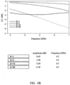
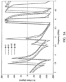
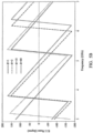
- Figs show, respectively, the amplitudes and phases of return losses of four different media having permittivities of 1, 2, 10 & 80 - a range which covers most applications expected to be encountered in industrial interface detection. Comparing the performance of a switch embodying the prior art sensor with a switch embodying a sensor according to the invention, it can be seen that the switch according to the invention shows a far greater change in both amplitude and phase with changes in permittivity. This is particularly so when the drive frequency is close to the designed mid-point frequency f 0 but it can also be seen that distinct separations of both amplitude and phase can be observed at different frequency points and thus switching point decisions can be made at these points as well.
- a level switch can be configured to operate by observing an amplitude difference of the return loss, by observing an amplitude and frequency difference of the return loss, by observing an amplitude, phase, and frequency difference of the return loss, by comparing a permittivity difference derived from the return loss with reference permittivities held in memory and by comparing an impedance difference derived from the returned loss with the reference impedance data held in memory.
- the invention may also be applied to a point level switch mounted in a non-penetrating manner on the outer surface of a vessel which is formed from a non-conducting material such as, for example, plastic, glass or ceramic; or mounted on a non-conducting window included in the wall of a vessel otherwise formed from a conducting material.
- a lower design frequency f 0 say around 3.5GHz is preferred as it will allow the microwave energy to penetrate the container wall and generate a large effective sensing volume more easily.
Landscapes
- Physics & Mathematics (AREA)
- Electromagnetism (AREA)
- Thermal Sciences (AREA)
- Fluid Mechanics (AREA)
- General Physics & Mathematics (AREA)
- Measurement Of Levels Of Liquids Or Fluent Solid Materials (AREA)
- Measurement Of Velocity Or Position Using Acoustic Or Ultrasonic Waves (AREA)
Applications Claiming Priority (3)
| Application Number | Priority Date | Filing Date | Title |
|---|---|---|---|
| GB1721252.3A GB2569540A (en) | 2017-12-19 | 2017-12-19 | Improvements in or relating to interface detection |
| PCT/GB2018/053643 WO2019122831A1 (en) | 2017-12-19 | 2018-12-17 | Improvements in or relating to interface detection |
| EP18822468.7A EP3729014B1 (de) | 2017-12-19 | 2018-12-17 | Verbesserungen an oder im zusammenhang mit schnittstellenerkennung |
Related Parent Applications (1)
| Application Number | Title | Priority Date | Filing Date |
|---|---|---|---|
| EP18822468.7A Division EP3729014B1 (de) | 2017-12-19 | 2018-12-17 | Verbesserungen an oder im zusammenhang mit schnittstellenerkennung |
Publications (2)
| Publication Number | Publication Date |
|---|---|
| EP4542609A2 true EP4542609A2 (de) | 2025-04-23 |
| EP4542609A3 EP4542609A3 (de) | 2025-07-02 |
Family
ID=61009033
Family Applications (2)
| Application Number | Title | Priority Date | Filing Date |
|---|---|---|---|
| EP18822468.7A Active EP3729014B1 (de) | 2017-12-19 | 2018-12-17 | Verbesserungen an oder im zusammenhang mit schnittstellenerkennung |
| EP25154485.4A Pending EP4542609A3 (de) | 2017-12-19 | 2018-12-17 | Verbesserungen an oder im zusammenhang mit schnittstellenerkennung |
Family Applications Before (1)
| Application Number | Title | Priority Date | Filing Date |
|---|---|---|---|
| EP18822468.7A Active EP3729014B1 (de) | 2017-12-19 | 2018-12-17 | Verbesserungen an oder im zusammenhang mit schnittstellenerkennung |
Country Status (5)
| Country | Link |
|---|---|
| US (1) | US11506528B2 (de) |
| EP (2) | EP3729014B1 (de) |
| CN (1) | CN111512125B (de) |
| GB (1) | GB2569540A (de) |
| WO (1) | WO2019122831A1 (de) |
Families Citing this family (4)
| Publication number | Priority date | Publication date | Assignee | Title |
|---|---|---|---|---|
| GB2583361A (en) * | 2019-04-25 | 2020-10-28 | Rosemount Measurement Ltd | Microwave-based method and apparatus for monitoring a process variable |
| DE102019008010B3 (de) * | 2019-11-18 | 2021-02-18 | Baumer Electric Ag | Sensorsystem und Verfahren zur Erfassung eines Pegelstandes eines Mediums |
| EP3851814B1 (de) * | 2020-01-16 | 2025-03-05 | Krohne Messtechnik GmbH | Füllstandssensor zur detektion eines füllstands eines füllmediums in einem behälter |
| EP3929572A1 (de) | 2020-06-25 | 2021-12-29 | Rosemount Tank Radar AB | Vorrichtung zur ermittlung der änderung einer dielektrizitätskonstante |
Citations (2)
| Publication number | Priority date | Publication date | Assignee | Title |
|---|---|---|---|---|
| US5675259A (en) | 1995-09-14 | 1997-10-07 | The United States Of America As Represented By The Administrator Of The National Aeronautics And Space Administration | Method and apparatus for measuring fluid flow |
| WO2010064023A1 (en) | 2008-12-06 | 2010-06-10 | Mobrey Limited | Improvements in or relating to level sensors |
Family Cites Families (16)
| Publication number | Priority date | Publication date | Assignee | Title |
|---|---|---|---|---|
| AU5510098A (en) * | 1996-11-22 | 1998-06-29 | Berwind Corporation | Material level sensing |
| DE19934041C2 (de) * | 1999-07-16 | 2002-11-28 | Winfried Schernus | Füllstand-Sensorvorrichtung |
| AU2002218183A1 (en) * | 2000-09-27 | 2002-04-08 | Endress+Hauser Gmbh + Co. Kg | Method for detecting the limit state of a material, and device therefor |
| US6801157B2 (en) * | 2002-10-02 | 2004-10-05 | Magnetrol International, Inc. | Guided wave radar level transmitter |
| US6867729B2 (en) * | 2003-07-30 | 2005-03-15 | Magnetrol International | Guided wave radar level transmitter with automatic velocity compensation |
| JP4505629B2 (ja) * | 2004-01-19 | 2010-07-21 | 国立大学法人静岡大学 | 界面検出装置及び界面検出方法 |
| JP2005345374A (ja) * | 2004-06-04 | 2005-12-15 | Aloka Co Ltd | 界面検出装置 |
| JP2005345372A (ja) * | 2004-06-04 | 2005-12-15 | Aloka Co Ltd | 界面検出装置 |
| DE102006019191A1 (de) * | 2006-04-21 | 2007-10-25 | Endress + Hauser Gmbh + Co. Kg | Verfahren zur Ermittlung und Überwachung des Füllstands eines Mediums in einem Behälter |
| US20080065059A1 (en) * | 2006-09-08 | 2008-03-13 | Marc Lukowiak | Microwave devices for transcutaneous treatments |
| DE102008016829A1 (de) * | 2008-04-01 | 2009-10-08 | KROHNE Meßtechnik GmbH & Co. KG | Füllstandschalter und Sensorelement für einen Füllstandschalter |
| US8018373B2 (en) * | 2008-12-19 | 2011-09-13 | Rosemount Tank Radar Ab | System and method for filling level determination |
| US9069056B2 (en) * | 2012-10-17 | 2015-06-30 | Magnetrol International, Incorporated | Guided wave radar probe reference target |
| US9476753B2 (en) * | 2014-03-28 | 2016-10-25 | Honeywell International Inc. | Feed-through for GWR measurements in tanks |
| DE102015202448A1 (de) * | 2015-02-11 | 2016-08-11 | Vega Grieshaber Kg | Auswerteverfahren für einen TDR-Grenzstandschalter |
| HUE040669T2 (hu) | 2015-07-15 | 2019-03-28 | Grieshaber Vega Kg | Töltésszintmérõ készülék |
-
2017
- 2017-12-19 GB GB1721252.3A patent/GB2569540A/en not_active Withdrawn
-
2018
- 2018-12-17 CN CN201880081544.1A patent/CN111512125B/zh active Active
- 2018-12-17 US US16/771,311 patent/US11506528B2/en active Active
- 2018-12-17 EP EP18822468.7A patent/EP3729014B1/de active Active
- 2018-12-17 WO PCT/GB2018/053643 patent/WO2019122831A1/en not_active Ceased
- 2018-12-17 EP EP25154485.4A patent/EP4542609A3/de active Pending
Patent Citations (2)
| Publication number | Priority date | Publication date | Assignee | Title |
|---|---|---|---|---|
| US5675259A (en) | 1995-09-14 | 1997-10-07 | The United States Of America As Represented By The Administrator Of The National Aeronautics And Space Administration | Method and apparatus for measuring fluid flow |
| WO2010064023A1 (en) | 2008-12-06 | 2010-06-10 | Mobrey Limited | Improvements in or relating to level sensors |
Non-Patent Citations (1)
| Title |
|---|
| J BAKER-JARVIS ET AL.: "Analysis of an open-ended coaxial probe with lift-off for nondestructive testing", IEEE TRANSACTIONS ON INSTRUMENTATION AND MEASUREMENT, vol. 43, October 1994 (1994-10-01) |
Also Published As
| Publication number | Publication date |
|---|---|
| US20200340845A1 (en) | 2020-10-29 |
| GB2569540A (en) | 2019-06-26 |
| EP3729014B1 (de) | 2025-01-29 |
| EP3729014A1 (de) | 2020-10-28 |
| CN111512125B (zh) | 2022-06-03 |
| EP4542609A3 (de) | 2025-07-02 |
| CN111512125A (zh) | 2020-08-07 |
| US11506528B2 (en) | 2022-11-22 |
| WO2019122831A1 (en) | 2019-06-27 |
| GB201721252D0 (en) | 2018-01-31 |
Similar Documents
| Publication | Publication Date | Title |
|---|---|---|
| EP3729014B1 (de) | Verbesserungen an oder im zusammenhang mit schnittstellenerkennung | |
| US7855676B2 (en) | Radar level gauge system with leakage detection | |
| CN104285134A (zh) | 用于确定和/或监控介质的料位或介电常数的设备 | |
| US12266841B2 (en) | Antenna for measuring dielectric values | |
| CN103308778B (zh) | 介电常数测量装置 | |
| US20170356858A1 (en) | Methods and apparatuses for analysing fluid samples | |
| US12153000B2 (en) | Microstrip-type microwave sensor | |
| Raveendranath et al. | Broadband coaxial cavity resonator for complex permittivity measurements of liquids | |
| US12241853B2 (en) | Dielectric-constant measuring device | |
| US20130283892A1 (en) | Cavity resonator | |
| US20070090846A1 (en) | Method and device for complex permittivity measurements as a function of frequency | |
| JP2004519661A (ja) | 材料のリミットレベルの捕捉検出方法およびこのための装置 | |
| EP3959510B1 (de) | Mikrowellenbasiertes verfahren und vorrichtung zur überwachung einer prozessvariablen | |
| CN114829914A (zh) | 用于确定介电值的测量设备 | |
| EP3105549B1 (de) | Messvorrichtung | |
| RU2536164C1 (ru) | Устройство для определения концентрации смеси веществ | |
| US12399143B2 (en) | Temperature-compensated dielectric-constant measuring device | |
| RU2424508C1 (ru) | Устройство для измерения физических свойств жидкости | |
| EP3929572A1 (de) | Vorrichtung zur ermittlung der änderung einer dielektrizitätskonstante | |
| Ali et al. | Planar microwave sensor using interleaved cascaded symmetric SRR for fluidic analysis | |
| Jain et al. | Design of Complementary Meander Shaped Resonator for Adulteration Testing | |
| Khan | A method for measuring dielectric properties of non-magnetic liquids and predicting their contamination level | |
| Ja et al. | Evaluation of Water Content in Milk Using Microwave Transmission Approach with Horn Antenna | |
| RU2247334C1 (ru) | Сигнализатор уровня вещества в емкости | |
| Prokhorenkov et al. | Detection of level and interface position of substances in tanks by radiofrequency techniques |
Legal Events
| Date | Code | Title | Description |
|---|---|---|---|
| PUAI | Public reference made under article 153(3) epc to a published international application that has entered the european phase |
Free format text: ORIGINAL CODE: 0009012 |
|
| STAA | Information on the status of an ep patent application or granted ep patent |
Free format text: STATUS: THE APPLICATION HAS BEEN PUBLISHED |
|
| AC | Divisional application: reference to earlier application |
Ref document number: 3729014 Country of ref document: EP Kind code of ref document: P |
|
| AK | Designated contracting states |
Kind code of ref document: A2 Designated state(s): AL AT BE BG CH CY CZ DE DK EE ES FI FR GB GR HR HU IE IS IT LI LT LU LV MC MK MT NL NO PL PT RO RS SE SI SK SM TR |
|
| REG | Reference to a national code |
Ref country code: DE Ref legal event code: R079 Free format text: PREVIOUS MAIN CLASS: H01H0029000000 Ipc: G01F0023284000 |
|
| PUAL | Search report despatched |
Free format text: ORIGINAL CODE: 0009013 |
|
| AK | Designated contracting states |
Kind code of ref document: A3 Designated state(s): AL AT BE BG CH CY CZ DE DK EE ES FI FR GB GR HR HU IE IS IT LI LT LU LV MC MK MT NL NO PL PT RO RS SE SI SK SM TR |
|
| RIC1 | Information provided on ipc code assigned before grant |
Ipc: H01H 29/00 20060101ALN20250526BHEP Ipc: G01F 23/284 20060101AFI20250526BHEP |
|
| STAA | Information on the status of an ep patent application or granted ep patent |
Free format text: STATUS: THE APPLICATION IS DEEMED TO BE WITHDRAWN |