EP4543159A1 - Struktur zur blockierung elektromagnetischer wellen - Google Patents
Struktur zur blockierung elektromagnetischer wellen Download PDFInfo
- Publication number
- EP4543159A1 EP4543159A1 EP24185999.0A EP24185999A EP4543159A1 EP 4543159 A1 EP4543159 A1 EP 4543159A1 EP 24185999 A EP24185999 A EP 24185999A EP 4543159 A1 EP4543159 A1 EP 4543159A1
- Authority
- EP
- European Patent Office
- Prior art keywords
- electromagnetic
- traffic lane
- wave blocking
- set forth
- road antenna
- Prior art date
- Legal status (The legal status is an assumption and is not a legal conclusion. Google has not performed a legal analysis and makes no representation as to the accuracy of the status listed.)
- Pending
Links
Images




Classifications
-
- H—ELECTRICITY
- H05—ELECTRIC TECHNIQUES NOT OTHERWISE PROVIDED FOR
- H05K—PRINTED CIRCUITS; CASINGS OR CONSTRUCTIONAL DETAILS OF ELECTRIC APPARATUS; MANUFACTURE OF ASSEMBLAGES OF ELECTRICAL COMPONENTS
- H05K9/00—Screening of apparatus or components against electric or magnetic fields
- H05K9/0073—Shielding materials
- H05K9/0081—Electromagnetic shielding materials, e.g. EMI, RFI shielding
- H05K9/0088—Electromagnetic shielding materials, e.g. EMI, RFI shielding comprising a plurality of shielding layers; combining different shielding material structure
-
- H—ELECTRICITY
- H01—ELECTRIC ELEMENTS
- H01Q—ANTENNAS, i.e. RADIO AERIALS
- H01Q1/00—Details of, or arrangements associated with, antennas
- H01Q1/52—Means for reducing coupling between antennas; Means for reducing coupling between an antenna and another structure
- H01Q1/521—Means for reducing coupling between antennas; Means for reducing coupling between an antenna and another structure reducing the coupling between adjacent antennas
-
- H—ELECTRICITY
- H01—ELECTRIC ELEMENTS
- H01Q—ANTENNAS, i.e. RADIO AERIALS
- H01Q1/00—Details of, or arrangements associated with, antennas
- H01Q1/52—Means for reducing coupling between antennas; Means for reducing coupling between an antenna and another structure
- H01Q1/526—Electromagnetic shields
Definitions
- the present invention relates to a structure blocking electromagnetic waves or not allowing electromagnetic waves to pass therethrough.
- the present invention further relates to a system for blocking electromagnetic waves, employing the structure.
- the structure blocking electromagnetic waves is a material of which a Faraday cage is comprised.
- noises of electromagnetic waves derived from various apparatuses cause malfunction in electronic devices.
- EMP electromagnétique pulse
- ETC electronic toll collection system
- Faraday case indicates a case or a cage made of an electric conductor, or a space surrounded with such a case or a cage.
- a metal is frequently used as an electric conductor of which Faraday cage is made.
- a structure blocking electromagnetic waves (100) including a first portion (110) comprised of a first material consisting of an electric conductor, characterized by a second portion (120) comprised of a second material having an electrical conductivity smaller than the same of the first material and a corrosion-resistance higher than the same of the first material, the second portion (120) covering therewith at least a part of a surface of the first portion (110).
- the first portion (110) has a first surface (111) exposed to electromagnetic waves, and a second surface (112) located in the other side of the first surface (111), the second portion (120) covering therewith at least the first surface (111) among the first and second surfaces (111, 112).
- At least the second portion (120A) among the first and second portions (110, 120) has a meshed structure.
- the second portion (120B) includes at least two auxiliary mesh materials (120X, 120Y) each having a mesh pattern different from others, the second portion (120B) covering therewith the first portion (110) in such a condition that the auxiliary mesh materials (120X, 120Y) are stacked one on another.
- the second portion (120, 120C) has a first surface covering a surface (111) of the first portion (110) therewith, and a second surface located in the other side of the first surface, the second surface being formed with convexes/concaves (113) or being wavy.
- At least one of a surface of the first portion (110) at which the first portion (110) makes contact with the second portion (120), and an outer surface of the second portion (120) has a surface roughness having a maximum height or a maximum depth shorter than a wavelength of external electromagnetic waves.
- first portion (110A) is in the form of a bar or a line
- second portion (120D) covers therewith a peripheral surface of the first portion (110A).
- the first material is one of gold, silver and copper.
- the second material is one of stainless steel and titanium.
- the second material does not allow electromagnetic waves to reflect, and allows electromagnetic waves to pass therethrough.
- the second material is one of glass and resin.
- the first portion (110C) is formed with convexes/concaves (113) at a surface at which the first portion (110C) makes contact with the second portion (120), has a meshed structure, or has a curved surface at which the first portion (110B) makes contact with the second portion (120).
- the second material is resin
- At least one of a surface of the first portion (110C), the other surface of the first portion (110C), and an outer surface of the second portion (120C) is formed with convexes/concaves (113, 122) for electromagnetic waves to randomly reflect, a height or a depth of the convexes/concaves (113, 122) being in the range of 1/10 to 1/50 both inclusive of a wavelength of external electromagnetic waves.
- the structure (100) further includes a ground wire (130) for grounding the first portion (110).
- the structure is in the form of a panel, the panel including at sides thereof a convex (101) and a concave (102) through which the panel (100C) is connected with neighboring panel(s).
- a system for blocking electromagnetic waves to be equipped on a traffic lane on which an electronic toll collection system is formed characterized in that the system includes at least one of a first electromagnetic-wave blocking structure (300, 350) formed between the traffic lane (201) and a second traffic lane (202) neighboring the traffic lane (201) and a second electromagnetic-wave blocking structure (360) formed short of an on-road antenna (210) in a direction in which a vehicle (251) runs in the traffic lane (201), the on-road antenna (210) being formed above the traffic lane (201), the first electromagnetic-wave blocking structure (300, 350) prevents electric waves transmitted from an on-road antenna (210A) located above the second traffic lane (202) and reflected from a vehicle (252) driving on the second traffic lane (202), from reaching an on-road antenna (210) located in the traffic lane (201), the second electromagnetic-wave blocking structure (360) is located within a path in which electric waves having been transmitted from the on-road antenna (
- the electromagnetic-wave blocking structure (300, 350) has a length equal to or greater than a length of a large-size vehicle.
- the electromagnetic-wave blocking structure is in the form of a wall (300).
- the wall (300) has a height higher than the on-road antenna (210) transmitting electric waves to a vehicle (251) driving on the traffic lane (201).
- the wall (300) has such a length along the traffic lane (201) that the on-road antenna (210) formed on the traffic lane (201) is located within the wall (300).
- the electromagnetic-wave blocking structure is in the form of a tunnel (350) covering the traffic lane (201) therewith.
- the tunnel (350) has such a length along the traffic lane (201) that the on-road antenna (210) formed on the traffic lane (201) is located within the tunnel (350).
- the second material has a corrosion-resistance higher than the same of the first material. Accordingly, in comparison with Faraday cage made of the first portion consisting only of the first material, Faraday cage made of the structure can have a higher resistance against outdoor environment in which water and other elements for corrosion exist. Thus, Faraday cage made of the structure in accordance with the present invention is more suitable to outdoor use than conventional Faraday cage.
- the system in accordance with the present invention can prevent interference in electric waves between on-road antennas located in two traffic lanes adjacent to each other, and hence, can prevent malfunction of ETC caused by such interference in electric waves.
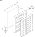
- FIG. 1 is a perspective view of an electromagnetic-wave blocking structure 100 in accordance with the first exemplary embodiment of the present invention.
- the electromagnetic-wave blocking structure 100 includes a first portion 110 made of a first material, a second portion 120 made of a second material, and a ground (earth) wire 130 grounding the first portion 110.
- the first portion 110 is cubic in shape.
- the first material of which the first portion 110 is made is an electrical conductor.
- the first material is a metal.
- the first material is a metal having a high electrical conductivity, such as gold, silver and copper.
- the second portion 120 is in the form of a flat board having a constant thickness.
- the second material of which the second portion 120 is made has both an electrical conductivity smaller than the same of the first material and a corrosion-resistance higher than the same of the first material.
- the second material is stainless steel or titanium.
- the cubic first portion 110 has a first surface 111 and a second surface 112 located at the other side of the first surface 111.
- the second portion 120 is designed to entirely cover therewith the first surface 111 of the first portion 110.
- a part of external electromagnetic waves having irradiated the second portion 120 is reflected at a surface of the second portion 120.
- the rest of the electromagnetic waves passes through the second portion 120, irradiates the first portion 110, and released to ground through the ground wire 130. That is, it is possible to prevent electromagnetic wave from leaking outside by grounding the first portion 110.
- the second material has a corrosion-resistance higher than the same of the first material. Accordingly, in comparison with conventional Faraday cage made of the first portion consisting only of the first material, Faraday cage made of the structure 100 can have a higher resistance against outdoor environment in which water and other elements for corrosion exist. Thus, Faraday cage made of the electromagnetic-wave blocking structure 100 is more suitable to outdoor use than conventional Faraday cage.
- the electromagnetic-wave blocking structure in accordance with the first exemplary embodiment is not to be limited to the above-mentioned structure, but can have various modifications.
- the electromagnetic-wave blocking structure 100 is designed to include the ground wire 130, it is not always necessary for the electromagnetic-wave blocking structure 100 to originally include the ground wire 130.
- the electromagnetic-wave blocking structure 100 is first constructed without including the ground wire 130, and then, the ground wire 130 may be additionally set up at a site where Faraday cage made of the electromagnetic-wave blocking structure 100 is put for connecting the first portion 110 to ground.
- the first portion 110 is designed to be cubic in shape, the first portion 110 may be designed to have any shape.
- the second portion 120 is designed to entirely cover therewith the first surface 111 of the first portion 110.
- the second portion 120 may be designed to partially cover therewith the first surface 111 of the first portion 110.
- the second portion 120 may be designed to cover therewith only the part of the first surface 111.
- the second portion 120 may be made of a material at which electromagnetic waves are not reflected, but through which electromagnetic waves pass, for instance, a glass or a resin. Electromagnetic waves pass through the second portion 120 made of a glass or a resin, then are absorbed into the first portion 110, and thereafter, released into ground through the ground wire 130.
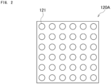
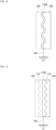
- FIG. 2 is a plan view of a first modification of the second portion 120.
- a second portion 120A in accordance with the first modification is designed to be meshed.
- the second portion 120A is formed with a plurality of same-sized holes 121 in a matrix.
- the second portion 120A By designing the second portion 120A to be meshed, it is possible to reduce a manufacturing cost by reducing a volume of the second portion 120A, accomplish a light weight, enhance a resistance against wind, and enhance visibility (a condition of the first portion 110 can be seen).
- Any mesh pattern may be selected.
- the second portion 120A may be in the form of a net.
- Any mesh pattern can be selected in dependence of outdoor environment.
- the holes 121 may have a diameter equal to one another.
- the holes 121 may have a diameter different from others.
- the holes 121 may be arranged not in a matrix, but randomly.
- the first portion 110 may be designed to be meshed similarly to the second portion 120A as well as the second portion 120A. That is, the electromagnetic-wave blocking structure 100 may be designed to be entirely meshed, in which case, the first portion 110 and the second portion 120A may be designed to have a common mesh pattern or a mesh pattern different from each other.
- FIG. 3 is a perspective view of a second modification of the second portion 120.
- a second portion 120B in the second modification is designed to be comprised of a first auxiliary portion 120X and a second auxiliary portion 120Y
- the first auxiliary portion 120X is identical with the second portion 120A illustrated in FIG. 2 .
- the second auxiliary portion 120Y has a mesh pattern in which a plurality of holes are formed in a matrix. A diameter of the holes of the second auxiliary portion 120Y and a distance (pitch) between the adjacent holes are different from those of the first auxiliary portion 120X.
- both the first and second auxiliary portions 120X and 120Y have a meshed structure, but mesh patterns of them are different from each other.
- the first and second auxiliary portions 120X and 120Y are stacked one on another to thereby cover therewith the first surface 111 of the first portion 110.
- the first auxiliary portion 120X covers therewith the first surface 111 of the first portion 110
- the second auxiliary portion 120Y covers therewith a surface of the first auxiliary portion 120X.
- the second portion 120B is designed to be comprised of the two auxiliary portions 120X and 120Y, but a number of the auxiliary portions comprising the second portion 120B is not to be limited to two.
- the second portion 120B may be designed to be comprised of three or more auxiliary portions.
- the second portion 120B comprised of a greater number of the auxiliary portions can have a higher effectiveness for blocking various electromagnetic waves.
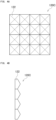
- FIG. 4A is a plan view of a third modification of the second portion 120
- FIG. 4B is a side view of the same.
- a second portion 120C in accordance with the third modification is formed at an outer surface (a surface located at the other side of a surface at which the second portion 120C makes contact with the first portion 110) with a plurality of convexes or projections 122.
- the convexes 122 have the same shape as one another and are arranged in a matrix.
- the convexes 122 are in the shape of a square pyramid.
- External electromagnetic waves are partially reflected at the second portions 120, 120A and 120B illustrated in FIGs. 1 to 3 .
- the second portion 120C By designing the second portion 120C to have the convexes 122 at an outer surface thereof, it is possible to cause electromagnetic waves to be randomly reflected (diffused), ensuring it possible to prevent energy caused by reflection from spreading.
- a shape of the convexes 122 is not to be limited to a square pyramid.
- the convexes 122 may be designed to have any shape.
- the second portion 120C may be designed to have concaves in place of the convexes 122 or designed to have a combination of concaves and the convexes 122.
- the second portion 120C may be designed to have a wavy surface in place of the convexes 122.
- the convexes/concaves have a height/depth in the range of about 1/10 to about 1/50 of a wavelength of electromagnetic waves.
- an ultraviolet ray has the shortest wavelength among external electromagnetic waves (electric waves existing in natural environment). Specifically, an ultraviolet ray has a wavelength in the range of about 10 to about 200 nanometers. Accordingly, the convexes/concaves are designed to have a height/depth in the range of about 2 to about 10 nanometers for a ultraviolet ray.
- the convexes/concaves have a height/depth in the range of about 1/10 to about 1/50 of a wavelength of electromagnetic waves.
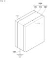
- FIG. 5 is a perspective view of an electromagnetic-wave blocking structure 100A in accordance with the second exemplary embodiment of the present invention.
- the second portion 120 is designed to cover therewith only one of surfaces (the first surface 111) of the first portion 110. In contrast, the second portion 120 covers therewith opposite surfaces (the first surface 111 and the second surface 112) of the first portion 110 in the electromagnetic-wave blocking structure 100A.
- the second portion 120 By designing the second portion 120 to cover therewith both the first and second surfaces 111, 112 of the first portion 110, it is possible to enhance both a capability of absorbing electromagnetic waves and a resistance against outdoor environment, and further, it is no longer necessary to take into consideration which direction the electromagnetic-wave blocking structure 100A faces. That is, it was necessary in the electromagnetic-wave blocking structure 100 to direct the second portion 120 so as to be exposed to external electromagnetic waves, but it is no longer necessary in the electromagnetic-wave blocking structure 100A to do so, because the first portion 110 is covered at opposite sides with the second portion 120.
- FIG. 6 is a perspective view of an electromagnetic-wave blocking structure 100B in accordance with the third exemplary embodiment of the present invention.
- a first portion 110A is in the form of a rod (bar) or a wire, and a second portion 120D is designed to cover therewith a circumferential surface of the first portion 110A.
- the electromagnetic-wave blocking structure 100B provides the same advantages as those provided by the electromagnetic-wave blocking structure 100.
- the electromagnetic-wave blocking structure 100B being in the form of a wire, a meshed electromagnetic-wave blocking structure can be obtained.
- the first portion 110 is not in the form of a flat board (see FIG. 1 ), but is in the form of a rod or a wire.
- FIG. 7 is a perspective view of an electromagnetic-wave blocking structure 100C in accordance with the fourth exemplary embodiment of the present invention.
- the electromagnetic-wave blocking structure 100C is formed by designing the electromagnetic-wave blocking structure 100 as a square panel, for instance.
- the panel 100C (the electromagnetic-wave blocking structure 100C) is designed to have a convex portion 101 and a concave portion 102 in each of four peripheral sides at a common position. Both the convex portion 101 and the concave portion 102 is cubic in shape, and the convex portion 101 is fittable into the concave portion 102.
- the panel 100C and a panel (not illustrated) located adjacent to the panel 100C can be connected with each other by fitting the convex portion 101 and the concave portion 102 of the panel 100C into the concave portion 102 and the convex portion 101 of the adjacent panel, respectively.
- the convex portion 101 and the concave portion 102 may be designed to have any shape as long as the convex portion 101 is fittable into the concave portion 102.
- the first portion 110 is sometimes unable to entirely absorb electromagnetic waves having passed through the second portion 120, and thus, partially reflect the electromagnetic waves.
- the first portion 110 is designed to have such a shape that can cope with this problem in place of the above-mentioned flat board.
- the first portion 110 is designed to have such a structure that randomly reflects electromagnetic waves which have not been absorbed into the first portion 110.
- FIG. 8 is a cross-sectional view of a first portion 110B in accordance with the first example of the fifth exemplary embodiment.
- the first portion 110B has a wavy surface at which the first portion 110B makes contact with the second portion 120. Most of electromagnetic waves having passed through the second portion 120 is absorbed into the first portion 110B, and then, is discharged to ground through the ground wire 130. Electromagnetic waves having not been absorbed into the first portion 110B are caused to randomly reflect at the wavy surface of the first portion 110B, and then, are attenuated.
- a shape of the first portion 110B is not to be limited to be wavy.
- the first portion 110B may have any shape, if it is curved.
- a second material of which the second portion 120 is made is preferable a resin. If a glass or a metal is selected as a second material, the second portion 120 is necessary to have a shape in line with a wavy shape of the first portion 110B. If a resin is selected as a second material, it is possible to make the second portion 120 merely by coating a liquid resin onto a wavy surface of the first portion 110B, and drying the resin, ensuring much reducing steps of manufacturing the second portion 120.
- the first portion 110B may be covered at opposite surfaces thereof with the second portions 120.
- FIG. 9 is a cross-sectional view of a first portion 110C in accordance with the second example of the fifth exemplary embodiment.
- the first portion 110C is regularly formed at a surface thereof (the first surface 111 in FIG. 1 ) at which the first portion 110C makes contact with the second portion 120, with convexes 113 similar in structure to the convexes 122 illustrated in FIG. 4 .
- electromagnetic waves having not been absorbed into the first portion 110C are caused to randomly reflect at the convexes 113 formed on a surface of the first portion 110C, and then, are attenuated.
- the convexes 133 may be designed to have any shape.
- the first portion 110C may be designed to have concaves in place of the convexes 113, or have a combination of the convexes 113 and concaves.
- the first portion 110C may be designed to include the convexes 113 at a surface (the second surface 112 in FIG. 1 ) located at the other side of the surface on which the convexes 113 are formed, in which case, the convexes 113 may be covered with the second portion 120 made of a resin.
- the first portion 110 may be designed to be meshed, similarly to the second portion 120A (see FIG. 2 ).
- the first portion 110 By designing the first portion 110 to be meshed, it is possible to cause electromagnetic waves having not been absorbed into the firsts portion 110 to randomly reflect to thereby be attenuated, similarly to the first portion 110B having a wavy surface.
- the first portion 110 may be formed on the first surface 111 with minute convexes/concaves or the first surface 111 may be designed to be gritty.
- an ultraviolet ray has a shortest wavelength among external electric waves (electric waves existing in natural environment). Specifically, an ultraviolet ray has a wavelength in the range of about 10 to about 200 nanometers. Accordingly, it is actually possible to reflect external electromagnetic waves, even if a relatively large projection such as the convexes 113 is not formed on the first surface 111 of the first portion 110.
- the first surface 111 of the first portion 110 may be designed to sufficiently have convexes/concaves having a height/depth shorter than a wavelength of external electromagnetic waves (for instance, a ultraviolet ray). In other words, it is possible to cause electromagnetic waves to randomly reflect to thereby be attenuated, if the first surface 111 has a surface roughness having a maximum height/depth shorter than a wavelength of external electromagnetic waves.
- a wavelength of external electromagnetic waves for instance, a ultraviolet ray
- a second material of which the second portion 120 is made is preferable a resin in the case that the first surface 111 is formed with minute convexes/concaves.
- the first portion 110 may be formed at the opposite surfaces 111, 112 with minute convexes/concaves.
- the second portion 120 may be designed to have minute convexes/concaves on an outer surface.
- the sixth exemplary embodiment relates to a first example of an electromagnetic-wave blocking system employing the above-mentioned electromagnetic-wave blocking structure 100, 100A or 100C.
- ETC Electronic Toll Collection system
- ETC Electronic Toll Collection system
- an on-road antenna situated above a toll gate in a toll road and an on-board ETC device equipped with a vehicle.
- a toll for passing a toll road is automatically paid by radiocommunication made between the on-road antenna and the on-board ETC device.
- FIG. 10 is a perspective view of a toll gate in a toll road equipped with ETC.
- a toll road includes a first traffic lane 201 and a second traffic lane 202 adjacent to the first traffic lane 201.
- a toll gate is set for each of traffic lanes.
- the first traffic lane 201 as an example.
- ETC equipped in the first traffic lane 201 includes an on-road antenna 210 transmitting radio waves to an on-board ETC device equipped in a vehicle, a display panel displaying a toll, and a bar 230 opening or shutting the first traffic lane 210.
- the on-road antenna 210 is supported by a stand 211 so as to straddle the first traffic lane 201.
- the on-road antenna 210 is located above and at the center of the first traffic lane 201, and downwardly transmits radio waves to a vehicle 251 driving in the first traffic lane 201.
- a toll is displayed in the display panel 220.
- the bar 230 is kept closed, and when a toll is paid, the bar 230 is open.
- the bar 230 is closed again.
- the on-road antenna 210 detects the vehicle 251, and transmits a radio wave to the vehicle 251.
- the on-board ECT device equipped in the vehicle 251 receives the radio wave having been transmitted from the on-road antenna 210, and then, transmits ID information to the on-road antenna 210 so that the on-road antenna 210 can identify the vehicle 251.
- the bar 230 is open after a toll was paid through radio-wave communication made between the on-road antenna 210 and the on-board ETC device.
- the on-road antenna 210A located in the second traffic lane 202 transmits a radio wave to the coming vehicle 252, similarly to the on-road antenna 210.
- a part of radio waves having been transmitted from the on-road antenna 210A is received in the on-board ETC device of the vehicle 252, but a part of radio waves having not been received in the on-board ETC device sometimes reflects at the vehicle 252.
- a part of the reflected radio waves is received in the on-road antenna 210 located in the first traffic lane 201, resulting in that the on-road antenna 210 doubly receives both a radio wave having been transmitted from the on-board ETC device of the vehicle 251 and a radio wave having been reflected at the vehicle 252.
- the on-road antenna 210 resultingly judges double reception of radio waves as an error, and thus, the bar 230 is not open, but is kept closed. Thus, the vehicle 251 is not allowed to pass a toll gate.
- ETC ETC cannot accurately judge whether the vehicle 251 is allowed to pass a toll gate
- the malfunction of ETC is caused by the interference in radio waves of the on-road antennas 210 and 210A across the two traffic lanes 201 and 202 located adjacent to each other.
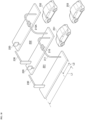
- FIG. 11 is a front view of the electromagnetic-wave blocking system in accordance with a first example of the present exemplary embodiment.
- the electromagnetic-wave blocking system in accordance with the first example is formed as an electromagnetic-wave blocking wall 300.
- the electromagnetic-wave blocking wall 300 vertically stands between the first traffic lane 201 and the second traffic lane 202.
- the electromagnetic-wave blocking wall 300 causes electric waves having been reflected at the vehicle 252 driving in the second traffic lane 202 to be absorbed into or reflected at the electromagnetic-wave blocking wall 300, and thus, the reflected electric waves cannot reach the on-road antenna 210 located in the first traffic lane 201. Accordingly, the on-road antenna 210 receives only electric waves having been transmitted from the on-board ETC device of the vehicle 251 driving in the first traffic lane 201, ensuring that the above-mentioned double reception of electric waves is prevented to thereby prevent the malfunction of ETC.
- Walls of a toll gate in ETC are sometimes covered with fibers being able to highly absorb electromagnetic wave therein.
- reflection of electromagnetic waves is prevented only at walls of a toll gate, and thus, it is not possible to prevent electromagnetic waves having been reflected at the second traffic lane 202 from reaching the on-road antenna 210 located in the first traffic lane 201, resulting in that the above-mentioned problem caused by the reflection of electromagnetic waves from the adjacent traffic lane cannot be overcome. It is necessary to construct the electromagnetic-wave blocking wall 300 in order to completely overcome the problem.
- the electromagnetic-wave blocking wall 300 may be designed to have a length L1 (see FIG. 10 ) extending to the bar 230 from the on-road antenna 210, but preferably have a length L2 (see FIG. 10 ) within which the on-road antenna 210 is located (that is, a length across the on-road antenna 210), in which case, it is sufficient for the electromagnetic-wave blocking wall 300 to have a length covering a length of a vehicle, specifically, a length covering a length of a large-sized vehicle.
- the electromagnetic-wave blocking wall 300 has a height higher than a height of the on-road antenna 210.
- the electromagnetic-wave blocking wall 300 By designing the electromagnetic-wave blocking wall 300 to have such a height, since electromagnetic waves having been reflected at the adjacent second traffic lane 202 cannot go over the electromagnetic-wave blocking wall 300 to enter the first traffic lane 201, the electromagnetic waves having been reflected at the adjacent second traffic lane 202 are entirely absorbed into or reflected at the electromagnetic-wave blocking wall 300, and thus, cannot reach the on-road antenna 210.
- FIG. 12 is a front view of the electromagnetic-wave blocking system in accordance with a second example of the present exemplary embodiment.
- the electromagnetic-wave blocking system in accordance with the second example is formed as a tunnel 350 constructed so as to cover therewith the first traffic lane 201.
- the tunnel 350 causes electric waves having been reflected at the vehicle 252 driving in the second traffic lane 202 to be absorbed into or reflected at the tunnel 350, and thus, the reflected electric waves cannot reach the on-road antenna 210 located in the first traffic lane 201. Accordingly, the on-road antenna 210 receives only electric waves having been transmitted from the on-board ETC device of the vehicle 251 driving in the first traffic lane 201, ensuring that the above-mentioned double reception of electric waves is prevented to thereby prevent the malfunction of ETC.
- the tunnel 350 is designed to have such a height that the on-road antenna 210 can be located within the tunnel 350.
- the tunnel 350 is located within at least the length L2, and the tunnel 350 has a length equal to or greater than a length of a large-sized vehicle.
- the on-road antenna 210 is designed to transmit electric waves having a frequency of 5.8 GHz band in accordance with a predetermined standard (Standard DSRC).
- the electromagnetic-wave blocking wall 300 or the tunnel 350 is comprised of the electromagnetic-wave blocking structure including the first portion 110 and/or the second portion 120 formed with a surface thereof with the convexes 113 and 122, or the electromagnetic-wave blocking structure including the first portion 110 and/or the second portion 120 having a surface to which a predetermined surface roughness is applied, it is effective to design the convexes/concaves to have a height/depth in the range of 2 mm to 1 cm both inclusive.
- the seventh exemplary embodiment relates to a second example of an electromagnetic-wave blocking system employing the above-mentioned electromagnetic-wave blocking structure 100, 100A or 100C.
- the above-mentioned electromagnetic-wave blocking system in accordance with the sixth exemplary embodiment prevents a trouble caused by electric waves having been reflected at the adjacent second traffic lane 202 and having reached the on-road antenna 210 located in the first traffic lane 201. There is another reason causing such a trouble.
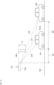
- FIG. 13 is a side view showing a positional relation among the on-road antenna 210, the precedent vehicle 251 and the following vehicle 253, and FIG. 14 is a plan view of FIG. 13 when viewed from the top.
- a part 311 of electric waves 310 having been transmitted from the on-road antenna 210 to the vehicle 251 driving in the first traffic lane 201 is sometimes reflected at a body (for instance, a roof or a side body) of the vehicle 251, and then, reaches the following vehicle 253 as a reflection wave 311A.
- the reflection wave 311A is further reflected at a body of the following vehicle 253, and then, reaches the on-road antenna 210 as a reflection wave 312.
- the reflection wave 312 having come from the following vehicle 253 and reaching the on-road antenna 210 may cause a problem that the on-road antenna 210 cannot accurately judge whether a vehicle or vehicles pass(es) a toll gate.
- the electromagnetic-wave blocking system in accordance with the present exemplary embodiment can overcome such a problem.
- the electromagnetic-wave blocking system includes an electromagnetic-wave blocking wall 360 located before or ahead of the on-road antenna 210 in a direction in which the vehicle 251 is driving
- the electromagnetic-wave blocking wall 360 is made of the electromagnetic-wave blocking structure 100, 100A or 100C, and is in the form of a flat board.
- the on-road antenna 210 is set to transmit an electric wave to the vehicle 251 when the vehicle 251 reaches at a distance M1 of 30 meters from the on-road antenna 210, for instance. Since a speed per hour of a vehicle passing over an ETC toll gate is decided by a law to be equal to or smaller than 20 km/h, it can be presumed that a distance M2 between the precedent vehicle 251 and the following vehicle 253 is about 20 meters.
- the electromagnetic-wave blocking wall 360 is positioned in accordance with these conditions as an example.
- the on-road antenna 210 has a height H determined such that electric waves transmitted from the on-road antenna 210 can reach the vehicle 251 without being blocked by the electromagnetic-wave blocking wall 260, but when the reflection wave 312 coming from the following vehicle 253 is directed to the on-road antenna 210, the electromagnetic-wave blocking wall 360 blocks the reflection wave 312. That is, the height H of the electromagnetic-wave blocking wall 360 is determined such that regardless of positions of upper and lower ends of the electromagnetic-wave blocking wall 360, electric waves having been transmitted from the on-road antenna 210 can reach the precedent vehicle 251, but the electromagnetic-wave blocking wall 360 is located in a path in which the reflection wave coming from the following vehicle 253 is directing to the on-road antenna 210.
- the electromagnetic-wave blocking wall 360 has a width W equal to a width of the first traffic lane 201. Since the on-road antenna 201 is located at the center of the first traffic lane 201, the on-road antenna 210 is horizontally and entirely covered with the electromagnetic-wave blocking wall 360.
- the electromagnetic-wave blocking system in accordance with the seventh exemplary embodiment prevents the reflection wave 312 coming from the following vehicle 253 from reaching the on-road antenna 210, and hence, prevents a problem caused by the reflection wave 312 coming from the following vehicle 253.
- the electromagnetic-wave blocking wall 360 may be employed together with the electromagnetic-wave blocking wall 300 and/or the tunnel 350.
- the electromagnetic-wave blocking structure in accordance with the present invention is broadly applicable to a building material of which a nuclear shelter is made, a material of which a protective facility and/or a protective device is(are) made against EMP (electromagnetic pulse) attack, and a cover for electronic devices against EMI (electromagnetic interference), for instance.
- the electromagnetic-wave blocking system using the electromagnetic-wave blocking structure is applicable further to a refuge facility for avoiding thunderbolt, as well as the above-mentioned ETC problem.
Landscapes
- Physics & Mathematics (AREA)
- Electromagnetism (AREA)
- Engineering & Computer Science (AREA)
- Microelectronics & Electronic Packaging (AREA)
- Shielding Devices Or Components To Electric Or Magnetic Fields (AREA)
- Details Of Aerials (AREA)
Applications Claiming Priority (1)
| Application Number | Priority Date | Filing Date | Title |
|---|---|---|---|
| JP2023179506A JP7856319B2 (ja) | 2023-10-18 | 2023-10-18 | 電磁波遮断構造体 |
Publications (1)
| Publication Number | Publication Date |
|---|---|
| EP4543159A1 true EP4543159A1 (de) | 2025-04-23 |
Family
ID=91781834
Family Applications (1)
| Application Number | Title | Priority Date | Filing Date |
|---|---|---|---|
| EP24185999.0A Pending EP4543159A1 (de) | 2023-10-18 | 2024-07-02 | Struktur zur blockierung elektromagnetischer wellen |
Country Status (3)
| Country | Link |
|---|---|
| US (1) | US20250133712A1 (de) |
| EP (1) | EP4543159A1 (de) |
| JP (1) | JP7856319B2 (de) |
Citations (7)
| Publication number | Priority date | Publication date | Assignee | Title |
|---|---|---|---|---|
| JPS6236565B2 (de) | 1980-12-19 | 1987-08-07 | Izumi Denki Kk | |
| JPH09257948A (ja) | 1996-03-26 | 1997-10-03 | Nikon Corp | ファラデーケージ |
| WO2002086848A1 (en) * | 2001-04-17 | 2002-10-31 | Dai Nippon Printing Co., Ltd. | Electromagnetic wave shielding member and display using the same |
| JP2003324300A (ja) * | 2002-05-01 | 2003-11-14 | Tdk Corp | 不要電波抑制方法及び道路付帯設備 |
| US20070291463A1 (en) * | 2005-02-25 | 2007-12-20 | Dai Nippon Printing Co., Ltd. | Electromagnetic Wave Shielding Filter |
| US11395446B2 (en) * | 2019-04-10 | 2022-07-19 | Glenair, Inc. | Electromagnetically shielding material |
| US20230309282A1 (en) * | 2020-11-18 | 2023-09-28 | Toppan Inc. | Electromagnetic wave attenuation film |
Family Cites Families (9)
| Publication number | Priority date | Publication date | Assignee | Title |
|---|---|---|---|---|
| US4825090A (en) * | 1988-02-09 | 1989-04-25 | Grabis Dietrich W | Shielding membrane |
| JPH09181474A (ja) * | 1995-12-25 | 1997-07-11 | Fuji Elelctrochem Co Ltd | 電磁波吸収材 |
| JPH11181911A (ja) * | 1997-12-17 | 1999-07-06 | Daido Steel Sheet Corp | 電磁波シールドパネルと電磁波シールド壁 |
| JP2006328859A (ja) | 2005-05-27 | 2006-12-07 | Sekisui Jushi Co Ltd | 電波音波吸収体、電波音波吸収パネル、電波吸収防音壁、道路付帯設備並びに電波及び音波の反射抑制方法 |
| JP2007067766A (ja) | 2005-08-31 | 2007-03-15 | Mitsui Eng & Shipbuild Co Ltd | 電波吸収体 |
| JP2012180630A (ja) | 2006-04-11 | 2012-09-20 | Matsuyama Keori Kk | 電磁波・音波吸収糸、電磁波・音波吸収織物、電磁波・音波吸収シート、電磁波・音波吸収プレート及び電磁波・音波吸収構造体 |
| JP2008182045A (ja) | 2007-01-24 | 2008-08-07 | Asahi Glass Co Ltd | 電波吸収体及びits/dsrc施設 |
| JP7156483B2 (ja) | 2020-11-18 | 2022-10-19 | 凸版印刷株式会社 | 電磁波減衰フィルム |
| JP7156484B2 (ja) | 2020-11-18 | 2022-10-19 | 凸版印刷株式会社 | 電磁波減衰フィルム |
-
2023
- 2023-10-18 JP JP2023179506A patent/JP7856319B2/ja active Active
-
2024
- 2024-06-26 US US18/754,974 patent/US20250133712A1/en active Pending
- 2024-07-02 EP EP24185999.0A patent/EP4543159A1/de active Pending
Patent Citations (7)
| Publication number | Priority date | Publication date | Assignee | Title |
|---|---|---|---|---|
| JPS6236565B2 (de) | 1980-12-19 | 1987-08-07 | Izumi Denki Kk | |
| JPH09257948A (ja) | 1996-03-26 | 1997-10-03 | Nikon Corp | ファラデーケージ |
| WO2002086848A1 (en) * | 2001-04-17 | 2002-10-31 | Dai Nippon Printing Co., Ltd. | Electromagnetic wave shielding member and display using the same |
| JP2003324300A (ja) * | 2002-05-01 | 2003-11-14 | Tdk Corp | 不要電波抑制方法及び道路付帯設備 |
| US20070291463A1 (en) * | 2005-02-25 | 2007-12-20 | Dai Nippon Printing Co., Ltd. | Electromagnetic Wave Shielding Filter |
| US11395446B2 (en) * | 2019-04-10 | 2022-07-19 | Glenair, Inc. | Electromagnetically shielding material |
| US20230309282A1 (en) * | 2020-11-18 | 2023-09-28 | Toppan Inc. | Electromagnetic wave attenuation film |
Also Published As
| Publication number | Publication date |
|---|---|
| US20250133712A1 (en) | 2025-04-24 |
| JP2025069659A (ja) | 2025-05-01 |
| JP7856319B2 (ja) | 2026-05-11 |
Similar Documents
| Publication | Publication Date | Title |
|---|---|---|
| US4906998A (en) | Radio-frequency anechoic chamber | |
| US6950021B2 (en) | Electronic wall using high-resolution millimeter-wave radar in conjunction with multiple plane reflectors and retroreflectors | |
| KR20100072383A (ko) | 전자파 흡수체를 구비한 운송수단 용 자동 요금 징수 시스템, 운송용 장치, 건물형 구조물, 전자기기, 전자파 무반사실 | |
| US6509843B1 (en) | Electronic toll collection system | |
| US4823523A (en) | Electromagnetic radiation shielding enclosure and shielding components | |
| ES2282231T3 (es) | Unidades de antena. | |
| US20250133712A1 (en) | Structure blocking electromagnetic waves | |
| US4945362A (en) | Microwave shielding for satellite earth stations | |
| JP4698137B2 (ja) | 不要電波抑制構造及び電波吸収仕切壁 | |
| US4651160A (en) | Earth station antenna shield | |
| JP4194735B2 (ja) | 電波減衰体 | |
| CN109658649A (zh) | 一种电子围栏 | |
| DE102004002374A1 (de) | Verkleidung für eine Richtfunkantenne | |
| EP1195848B1 (de) | Mikrowellenabsorberwand | |
| JP3093417B2 (ja) | Pcパネルおよび建築物外壁 | |
| JP4835653B2 (ja) | 路車間通信システムに用いられる電波漏洩制限用壁 | |
| EP4668482A1 (de) | Verfahren und vorrichtung zur abschirmung eines festen störobjektes in einer radaranlage | |
| DE102023003645A1 (de) | Vorrichtung zur Minderung von Fehlalarmen aufgrund hoher Seitenstrahlung | |
| JP4098788B2 (ja) | 電波減衰体 | |
| Fujimori et al. | Ray tracing analysis of propagation characteristics in tunnels including transmitting antenna | |
| US20260047055A1 (en) | Shielding structure for electromagnetic waves | |
| JP2005086528A (ja) | 電波受信アンテナ用の妨害波シールド構造物 | |
| DE202008016945U1 (de) | Zusatzeinrichtung für eine Richtfunkantenne mit Verkleidung | |
| JP2007048791A (ja) | 道路用電磁波シールド材及び道路における電磁波シールド方法 | |
| JP2003075490A (ja) | 多重フェンスのある電波計測用テストサイト及びその標準設計方法 |
Legal Events
| Date | Code | Title | Description |
|---|---|---|---|
| PUAI | Public reference made under article 153(3) epc to a published international application that has entered the european phase |
Free format text: ORIGINAL CODE: 0009012 |
|
| STAA | Information on the status of an ep patent application or granted ep patent |
Free format text: STATUS: THE APPLICATION HAS BEEN PUBLISHED |
|
| AK | Designated contracting states |
Kind code of ref document: A1 Designated state(s): AL AT BE BG CH CY CZ DE DK EE ES FI FR GB GR HR HU IE IS IT LI LT LU LV MC ME MK MT NL NO PL PT RO RS SE SI SK SM TR |
|
| STAA | Information on the status of an ep patent application or granted ep patent |
Free format text: STATUS: REQUEST FOR EXAMINATION WAS MADE |
|
| 17P | Request for examination filed |
Effective date: 20250922 |