EP4544908A1 - Verschlussvorrichtung und vorrichtung zum entfernen von pflanzenschutzmitteln - Google Patents
Verschlussvorrichtung und vorrichtung zum entfernen von pflanzenschutzmitteln Download PDFInfo
- Publication number
- EP4544908A1 EP4544908A1 EP24202062.6A EP24202062A EP4544908A1 EP 4544908 A1 EP4544908 A1 EP 4544908A1 EP 24202062 A EP24202062 A EP 24202062A EP 4544908 A1 EP4544908 A1 EP 4544908A1
- Authority
- EP
- European Patent Office
- Prior art keywords
- container
- inflatable membrane
- opening
- phytosanitary product
- pneumatic circuit
- Prior art date
- Legal status (The legal status is an assumption and is not a legal conclusion. Google has not performed a legal analysis and makes no representation as to the accuracy of the status listed.)
- Pending
Links
Images


Classifications
-
- A—HUMAN NECESSITIES
- A01—AGRICULTURE; FORESTRY; ANIMAL HUSBANDRY; HUNTING; TRAPPING; FISHING
- A01M—CATCHING, TRAPPING OR SCARING OF ANIMALS; APPARATUS FOR THE DESTRUCTION OF NOXIOUS ANIMALS OR NOXIOUS PLANTS
- A01M7/00—Special adaptations or arrangements of liquid-spraying apparatus for purposes covered by this subclass
- A01M7/0082—Undercarriages, frames, mountings, couplings, tanks
-
- A—HUMAN NECESSITIES
- A01—AGRICULTURE; FORESTRY; ANIMAL HUSBANDRY; HUNTING; TRAPPING; FISHING
- A01M—CATCHING, TRAPPING OR SCARING OF ANIMALS; APPARATUS FOR THE DESTRUCTION OF NOXIOUS ANIMALS OR NOXIOUS PLANTS
- A01M7/00—Special adaptations or arrangements of liquid-spraying apparatus for purposes covered by this subclass
- A01M7/0089—Regulating or controlling systems
-
- A—HUMAN NECESSITIES
- A01—AGRICULTURE; FORESTRY; ANIMAL HUSBANDRY; HUNTING; TRAPPING; FISHING
- A01M—CATCHING, TRAPPING OR SCARING OF ANIMALS; APPARATUS FOR THE DESTRUCTION OF NOXIOUS ANIMALS OR NOXIOUS PLANTS
- A01M7/00—Special adaptations or arrangements of liquid-spraying apparatus for purposes covered by this subclass
- A01M7/0025—Mechanical sprayers
- A01M7/0032—Pressure sprayers
-
- B—PERFORMING OPERATIONS; TRANSPORTING
- B05—SPRAYING OR ATOMISING IN GENERAL; APPLYING FLUENT MATERIALS TO SURFACES, IN GENERAL
- B05B—SPRAYING APPARATUS; ATOMISING APPARATUS; NOZZLES
- B05B9/00—Spraying apparatus for discharge of liquids or other fluent material, without essentially mixing with gas or vapour
- B05B9/03—Spraying apparatus for discharge of liquids or other fluent material, without essentially mixing with gas or vapour characterised by means for supplying liquid or other fluent material
- B05B9/04—Spraying apparatus for discharge of liquids or other fluent material, without essentially mixing with gas or vapour characterised by means for supplying liquid or other fluent material with pressurised or compressible container; with pump
- B05B9/047—Spraying apparatus for discharge of liquids or other fluent material, without essentially mixing with gas or vapour characterised by means for supplying liquid or other fluent material with pressurised or compressible container; with pump supply being effected by follower in container, e.g. membrane or floating piston, or by deformation of container
-
- A—HUMAN NECESSITIES
- A01—AGRICULTURE; FORESTRY; ANIMAL HUSBANDRY; HUNTING; TRAPPING; FISHING
- A01M—CATCHING, TRAPPING OR SCARING OF ANIMALS; APPARATUS FOR THE DESTRUCTION OF NOXIOUS ANIMALS OR NOXIOUS PLANTS
- A01M7/00—Special adaptations or arrangements of liquid-spraying apparatus for purposes covered by this subclass
- A01M7/0082—Undercarriages, frames, mountings, couplings, tanks
- A01M7/0085—Tanks
Definitions
- the present invention relates to the field of agricultural spraying.
- the present invention relates to a closing device intended to cooperate with a container of phytosanitary product for an agricultural sprayer.
- the invention also relates to a device for extracting a phytosanitary product comprising such a closing device.
- the invention also relates to an agricultural machine comprising such an extraction device.
- the present invention therefore aims to solve the aforementioned problems by proposing a closing device intended to cooperate with a container of phytosanitary product and configured to facilitate and allow the evacuation of a phytosanitary product.
- Said device being adaptable to different standard containers, it is convenient and economical, but also allows a certain ergonomics of the agricultural spraying system for which the closing device is intended.
- the invention relates to a closure device intended to cooperate with a hydraulic rinsing circuit, with a pneumatic circuit for an agricultural spraying system, with a plant protection product outlet and with a container of plant protection product, the closure device comprising at least one bottom wall and at least one peripheral wall.
- the closure device is intended to close the container.
- the peripheral wall projecting from the bottom wall, the bottom wall have at least three through openings, namely a first opening, a second opening and a third opening, the first opening being configured to be connected to the plant protection product outlet allowing said plant protection product to be evacuated from said container, the second opening being on the one hand configured to open in a sealed manner into an inflatable membrane and on the other hand configured to be connected to an inlet of the pneumatic circuit, so as to allow an overpressure to be generated in the container by the expansion of the inflatable membrane by means of the pneumatic circuit, said third opening being configured to be connected to an inlet of said hydraulic rinsing circuit.
- the closure device according to the invention can be single-use or reusable. It allows, through its first opening, to evacuate the phytosanitary product contained in the container to which it is attached. Through its second opening, the closure device allows to inflate and deflate the inflatable membrane so as to facilitate the evacuation of the phytosanitary product from the container. Through its third opening, the closure device also allows the container and the inflatable membrane to be rinsed.
- the closure device is adaptable to any type of container, standard or not, and has the advantage of being compact, economical and ergonomic.
- the closing device further comprises an inflatable membrane, said inflatable membrane being connected to the second opening of the bottom wall, said inflatable membrane being configured to expand and/or contract by means of the pneumatic circuit, the inflatable membrane being arranged on the same side of the bottom wall as the peripheral wall.
- the inflatable membrane through its expansion, generates overpressure in the container.
- the inflatable membrane is connected to the second opening of the bottom wall and is configured to expand and/or contract by means of the pneumatic circuit. It is configured to expand and retract in the container, once the closure device placed on the container.
- the expansion of the inflatable membrane and the overpressure generated in the container allow the phytosanitary product to be sprayed contained in the container to be delivered to the first opening of the closure device connected to a phytosanitary product outlet during use of the closure device.
- the inflatable membrane can be a flexible, extensible membrane.
- the flexible expandable membrane is configured so that, when it expands under the action of the pneumatic circuit, it fits the internal wall of the container and allows all the phytosanitary product contained in the container to be pushed out of the container. In particular, it facilitates the evacuation of all the phytosanitary product from the container, even the liquid trapped in an irregularity in the container wall.
- the invention also relates to a device for extracting a phytosanitary product from a container comprising at least one closure device as briefly described above, at least one pneumatic circuit and at least one phytosanitary product outlet, said closure device comprising at least one inflatable membrane, at least one bottom wall and at least one peripheral wall projecting from the bottom wall, said bottom wall having at least two openings, a first opening and a second opening, the first opening being connected to a phytosanitary product outlet allowing said phytosanitary product to be evacuated from said container, the second opening being on the one hand connected to the inflatable membrane and on the other hand connected to a pneumatic circuit inlet, said inflatable membrane being configured to expand and/or contract by means of the pneumatic circuit, the inflatable membrane being arranged on the same side of the bottom wall as the peripheral wall.
- the closing device is intended to close a container.
- the pneumatic circuit connected to the closing device by its second opening, allows the expansion of the inflatable membrane which itself allows the routing of the phytosanitary product towards the phytosanitary product outlet so that it can be sprayed by a spray boom.
- the pneumatic circuit comprises at least one conduit, a distributor, a pressure regulator and a compressed air inlet, the conduit connecting the closing device to the distributor, itself connected by said conduit to the pressure regulator connected to the compressed air inlet, said pneumatic circuit being configured to allow the expansion of the inflatable membrane.
- the compressed air inlet carries compressed air to the pressure regulator, which allows the air pressure to be maintained and controlled.
- the regulator allows compressed air to be delivered at the desired pressure to the shut-off valve.
- the injection of air in the inflatable membrane allows the expansion of said membrane, which generates an overpressure in the can.
- the expansion of the inflatable membrane and the overpressure generated in the can allow the liquid to be sprayed to be conveyed to the first opening of the closure device connected to a phytosanitary product outlet.
- the pneumatic circuit further comprises a vacuum generator, said conduit connecting the vacuum generator to the distributor, said vacuum generator being configured to suck in the air contained in the inflatable membrane, causing it to contract.
- the vacuum generator allows the air contained in the inflatable membrane to be sucked out, which causes it to contract in the container.
- the pneumatic circuit further comprises a conduit, an air rinsing distributor and a pressure regulator, said conduit connecting the compressed air inlet to the pressure regulator, itself connected by said conduit to the air rinsing distributor, itself connected to the phytosanitary product outlet, said pneumatic circuit being configured to allow air rinsing of the phytosanitary product outlet.
- the compressed air supply carries compressed air to the pressure regulator, which maintains and controls the air pressure, then to the air flushing distributor before routing it into the plant protection product outlet duct, to the spray boom. Injecting air into the ducts up to the spray boom allows the ducts through which the sprayed plant protection product was delivered to be flushed with air.
- the pneumatic circuit here allows the evacuation of plant protection product particles remaining in the ducts.
- the extraction device further comprises a hydraulic rinsing circuit and in which the bottom wall of said closing device has a third through opening connected to an inlet of said hydraulic rinsing circuit, configured to allow rinsing of the container and the inflatable membrane.
- the hydraulic rinsing circuit allows the delivery of a rinsing liquid such as clear water to the third opening of the closure device, then into the container.
- Said hydraulic circuit is configured to rinse the container with the rinsing liquid, once the plant protection product has been evacuated.
- the hydraulic rinsing circuit allows the evacuation of the plant protection product particles remaining in the container.
- the hydraulic circuit prevents the plant protection product from stagnating in the container but also on the inflatable membrane.
- the invention also relates to a liquid spraying system comprising an extraction device as briefly described above and further comprising a canister configured to contain a phytosanitary product and on which said closure device is fixed, the can being on the one hand connected, by the first opening of the closure device, to a conduit of the outlet of the treatment liquid configured to convey the phytosanitary product from the can to at least one spray nozzle, the can being on the other hand connected by the third opening of the closure device to an inlet conduit of the hydraulic rinsing circuit configured to convey rinsing liquid into the can so that said rinsing liquid rinses said can, and said can being connected by the second opening of the closure device to an inlet conduit of the pneumatic circuit and to the inflatable membrane, said pneumatic circuit inlet conduit being configured to convey fluid into the inflatable membrane so that it expands in the enclosure of the can, the expansion of said inflatable membrane being configured to pressurize the phytosanitary product from the can so as to create a flow of said phytosanitary product towards the outlet of the phytosanitary product.
- the spraying system comprises a pressurized enclosure, the canister and the extraction device being arranged inside the pressurized enclosure.
- the invention also relates to an agricultural machine comprising a liquid spraying system as briefly described above.
- the invention relates to a spraying system comprising a can 2 and a device 1 for extracting a phytosanitary product.
- the can 2 is intended to contain phytosanitary product and the extraction device 1 is configured to allow and facilitate the extraction of the phytosanitary product outside the can 2 so as to be sprayed by the spraying system mounted on an agricultural machine such as an agricultural sprayer.
- the phytosanitary product extraction device 1 comprises at least one closing device 3, at least one pneumatic circuit 4 and at least one phytosanitary product outlet 5.
- the extraction device 1 may further comprise the container 2 and a hydraulic rinsing circuit 6 configured to allow the container 2 to be rinsed.
- can means any container of an active product, in other words a plant protection product, including potentially any type of tank originally containing the plant protection product.
- can also covers a container into which a plant protection product is transferred, in particular from a tank.
- Canister 2 is configured to contain the plant protection product.
- Canister 2 is a standardized canister or one not known in the prior art, having various shapes and volumes. In particular, it may contain plant protection liquid allowing the treatment of the plants on which it is sprayed.
- the closing device 3 is intended to close the container 2.
- the closing device 3 comprises at least one bottom wall 30 and at least one peripheral wall 31.
- the closing device 3 may, for example, take the form of a cap.
- the peripheral wall 31 projects from the bottom wall 30.
- the peripheral wall 31 may extend around the periphery of the bottom wall 30.
- Said peripheral wall 31 and said bottom wall 30 delimit a fixing housing 32.
- peripheral wall 31 is configured to cooperate with the container 2, so as to close the latter.
- the peripheral wall 31 has a thread configured to adapt to a screw thread of the container 2, and thus allow the container 2 to be closed.
- the peripheral wall 31 may comprise a clip system configured to cooperate with a complementary clip system present on the container 2, allowing the container 2 to be closed.
- the invention is not limited to these two methods of closing the container 2, but applies to any type of closing method allowing the container 2 to be closed by the closing device 3.
- the bottom wall 30 has at least three openings, namely a first opening 33, a second opening 34 and a third opening 35.
- the first opening 33 is configured to be connected to the phytosanitary product outlet 5, allowing the phytosanitary product contained in the container 2 to be evacuated from said container 2.
- the second opening 34 is on the one hand configured to open in a sealed manner into an inflatable membrane 36 and on the other hand to be connected to an inlet of the pneumatic circuit 4, so as to allow an overpressure to be generated in the container 2 by the expansion of the inflatable membrane 36 by means of the pneumatic circuit 4, and so as to allow the inflatable membrane 36 to be deflated if necessary.
- the extraction device 1 may further comprise a closing member (not shown) between the closing device 3 and the pneumatic circuit 4. Said closing member is then configured to prevent the flow of the phytosanitary product contained in the container 2, in particular by gravity when the container 2 is placed in the extraction device 1 or when the closing device 3 is placed on the container 2 for example.
- the closing member may for example be a tap, a standard coupler, etc.
- the third opening 35 is configured to be connected to an inlet of the hydraulic rinsing circuit 6.
- the closing device 3 may further comprise the inflatable membrane 36.
- the inflatable membrane 36 is connected to the second opening 34 of the bottom wall 30.
- the inflatable membrane 36 is configured to expand and/or contract by means of the pneumatic circuit 4.
- the inflatable membrane 36 is arranged on the same side of the bottom wall 30 as the peripheral wall 31. In other words, the inflatable membrane 36 is connected to the second opening 34, in the fixing housing 32.
- the inflatable membrane 36 is an extensible flexible membrane.
- the flexible expandable membrane is configured to, when it expands under the action of the pneumatic circuit, fit the internal wall of the container 2, as shown in the Figure 2 .
- the inflatable membrane 36 can fit all of the walls of the container 2. In other words, the walls of the container 2 delimiting its opening closed by the closing device 3 can also be covered by the flexible membrane 36.
- the inflatable membrane 36 may have a predetermined shape corresponding to the shape of the container 2, in particular the shape of the internal volume of the container 2. Under the action of the pneumatic circuit 4, the inflatable membrane 36 expands until it reaches its predetermined shape.
- the closing device 3 closes the container 2.
- the closing device 3 replaces the cap of the container 2.
- the closing device 3 is fixed to the container 2, so as to close its opening delimited by its wall.
- the fixing housing 32 is configured to house a portion of the wall of the container 2, making it possible to close the opening of said container 2.
- the bottom wall 30 of the closure device 3 is sized to correspond to the opening of the container 2 and the peripheral wall is configured to cooperate with the portion of the wall of the container 2.
- the peripheral wall 31 may be, on its internal surface intended to be in contact with the container 2, threaded.
- the external wall portion of the container 2, intended to be in contact with the peripheral wall 31 of the closure device 3, may be threaded.
- the threading of the peripheral wall 31 corresponds to the threading of the wall portion of the container 2, so that the closure device 3 is fixed to the container 2.
- the pneumatic circuit 4 is configured to allow the expansion of the inflatable membrane 36.
- the inflatable membrane 36 is completely retracted and arranged inside the container 2.
- the pneumatic circuit 4 conveys air into the inflatable membrane 36, so as to allow its expansion and generate an overpressure in the container 2.
- the expansion of the inflatable membrane 36 and the overpressure generated in the container 2 allow the liquid to be sprayed to be conveyed to the first opening 33 of the closure device 3 connected to the plant protection product outlet 5.
- the pneumatic circuit 4 may comprise a control device (not shown) configured to control the quantity of air to be injected into the inflatable membrane 36.
- the outlet of the phytosanitary product 5 may comprise a conduit 50, a valve 51 and a pump 52.
- the conduit 50 is configured to convey the phytosanitary product from the closure device 3 to the spray boom of the agricultural machine.
- the conduit 50 connects the first opening 33 of the closure device 3 to the valve 51, the valve 51 to the pump 52 and the pump 52 to the spray boom.
- pump 52 activates the circulation of the phytosanitary product from container 2 to the inlet of pump 52.
- Valve 51 may for example be a simple non-return valve.
- the valve 51 allows the passage of the phytosanitary product in the direction of evacuation of the phytosanitary product from the can 2, that is to say from the closing device 3 towards the spray bar. On the contrary, the valve 51 prevents the circulation of the phytosanitary product in the opposite direction, that is to say towards the can 2.
- the phytosanitary product is conveyed from the container 2, towards the valve 51 then towards the inlet of the pump 52 to then be conveyed towards the spray bar.
- the extraction device 1 can also here further comprise a closing member (not shown) between the closing device 3 and the valve 51.
- the closing member is configured to prevent the flow of the phytosanitary product contained in the container 2, in particular by gravity when placing the container 2 in the extraction device 1 or when placing the closing device 3 on the container 2, for example.
- the closing member may, for example, be a tap, a standard coupler, etc.
- the pneumatic circuit 4 shown on the Figure 3 may comprise a conduit 40 connecting the closing device 3 to a distributor 41, itself connected by the conduit 40 to a pressure regulator 42 connected to a compressed air inlet 43.
- the pipe 40 connects the second opening 34 of the closing device 3 to the compressed air inlet 43.
- the compressed air inlet 43 conveys compressed air to the pressure regulator 42 which allows the air pressure to be maintained and controlled.
- the injection of compressed air into the inflatable membrane 36 allows the expansion of said membrane 36, which generates an overpressure in the can 2.
- the expansion of the inflatable membrane 36 and the overpressure generated in the can 2 allow the liquid to be sprayed to be conveyed to the first opening 33 of the closure device 3 connected to a phytosanitary product outlet.
- the pneumatic circuit 4 may further comprise a conduit 44 connecting the compressed air inlet 43 to a pressure regulator 45, itself connected by the conduit 44 to an air rinsing distributor 46.
- the air rinsing distributor 46 is also connected by another conduit to a valve 47 connected to the outlet of the phytosanitary product 5.
- the compressed air inlet 43 conveys compressed air to the pressure regulator 45 which allows the air pressure to be maintained and controlled, then to the air rinsing distributor 46 which allows it to be conveyed into the duct of the plant protection product outlet 5, to the spray bar.
- the injection of air into the ducts up to the spray bar makes it possible to rinse with air the ducts through which the sprayed plant protection product was conveyed.
- the pneumatic circuit 4 here makes it possible to evacuate the particles of plant protection product remaining in the ducts.
- the pneumatic circuit 4 may further comprise a conduit 48 connecting the compressed air inlet 43 to a distributor 49, itself connected by the conduit 48 to a vacuum generator 7. Furthermore, the distributor 41 is connected to the vacuum generator 7.
- the vacuum generator 7 is responsible for accelerating the air present in the conduit 48 in order to create a depression in this conduit 48, so as to suck the air present in the inflatable membrane 36 and thus deflate it.
- the pressure inside the inflatable membrane 36 may then possibly be lower than atmospheric pressure. Said vacuum generator 7 operates thanks to the venturi effect.
- the distributor 49 makes it possible to activate the vacuum generator 7 when it is desired to deflate the inflatable membrane 36.
- the vacuum generator 7 would then allow the air contained in the inflatable membrane 36, which has been decompressed by the distributor 41, to be sucked out, which would cause it to contract in the container 2.
- the vacuum generator 7 can, for example, be a venturi.
- a valve 471 allowing the inflatable membrane 36 to be decompressed without passing through the vacuum generator 7.
- the inflatable membrane 36 is then not drawn into a vacuum, the pressure inside the inflatable membrane 36 cannot therefore be lower than atmospheric pressure.
- the distributor 49 allows the compressed air to pass and the inflatable membrane 36 is decompressed, by means of the vacuum generator 7, through the distributor 41, which is described previously.
- the distributor 49 does not allow the compressed air to pass, the distributor 41 then being in a position configured to allow the air contained in the inflatable membrane 36 to pass, which has no other choice but to exit through the valve 471.
- the hydraulic rinsing circuit 6 is connected by a conduit 60 to a valve 61, itself connected to the flap 62, itself connected to the third opening 35 of the closing device 3.
- the hydraulic rinsing circuit 6 allows the routing of rinsing liquid such as clear water through the conduit 60, then through the valve 61 and the flap 62 to the third opening 35 of the closing device 3, then into the container 2.
- Valve 62 may for example be a simple non-return valve.
- the valve 62 allows the passage of clear water towards the inside of the container 2, i.e. towards the closing device 3. On the contrary, the valve 62 prevents the circulation of clear water in the opposite direction, i.e. towards the hydraulic circuit 6.
- the extraction device 1 can advantageously further comprise a closing member (not shown) between the closing device 3 and the valve 62.
- Said closing member is configured to prevent the flow of the phytosanitary product contained in the container 2, in particular by gravity when the container 2 is placed in the extraction device 1 or when the device is placed closure 3 on the container 2 for example.
- the closing device can for example be a tap, a standard coupler, etc.
- the hydraulic rinsing circuit 6 is configured to rinse with clean water, for example, the container 2 once the phytosanitary product has been evacuated.
- the hydraulic rinsing circuit 6 makes it possible to evacuate the particles of phytosanitary product remaining in the container 2, as well as on the inflatable membrane 36.
- the hydraulic circuit 6 prevents stagnation of the phytosanitary product in the container 2.
- the vacuum generator 7 of the pneumatic circuit 4 can suck in the air contained in the inflatable membrane 36, which would first pass through the distributor 41 which would allow the air to be conveyed to the vacuum generator 7, which would cause it to contract in the container 2.
- the hydraulic rinsing circuit 6 conveys rinsing liquid such as clear water into the container 2, through the conduit 60, then through the valve 61 and the flap 62 to the third opening 35 of the closing device 3.
- the clear water thus conveyed into the container 2 makes it possible to evacuate the particles of phytosanitary product remaining in the container 2 and on the inflatable membrane 36.
- the clear water containing the particles of phytosanitary product then forms gray water.
- This gray water is evacuated through pipe 50.
- the gray water is then conveyed, for example, to the spray boom of the agricultural machine or to a tank allowing its storage before spraying.
- the compressed air inlet 43 of the pneumatic circuit 4 conveys compressed air to the pressure regulator 45 and then to the air rinsing distributor 46 before conveying it into the conduit of the plant protection product outlet 5, to the spray bar.
- the injection of air into the conduits up to the spray bar makes it possible to rinse with air the conduits through which the sprayed plant protection product and/or the gray water have been conveyed.
- the pneumatic circuit 4 here makes it possible to evacuate the particles of plant protection product remaining in the conduits.
- the closing device 3 may be single-use or reusable.
- the closing device 3 In the case where the closing device 3 is reusable, it can be removed from the empty container 2 and rinsed then mounted on another filled container 2 containing the same phytosanitary product or any other liquid.
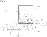
- FIG. 4 and the Figure 5 schematically represent a particular embodiment, in which the container and the cap are arranged in a pressurized enclosure.
- the Figure 4 is identical to the Figure 3 , except as it shows the pressurized enclosure 70.
- the Figure 5 is identical to the Figure 1 , except as it shows the pressurized enclosure 70.
- the pressurized enclosure 70 is configured to withstand significant pressures, in particular of the order of or greater than 6 bars, for example of the order of 10 bars. It is then possible to pressurize this pressurized enclosure 70 at the same time as the fluid contained inside the can 2, thanks to the air regulator 42. This makes it possible to maintain the same pressure inside the pressurized enclosure 70 and inside the inflatable membrane 36 and consequently inside the can 2. Consequently, there is then no difference in pressure between the inside and the outside of the can 2. It is therefore possible to apply greater pressure to the can 2, regardless of its intrinsic physical characteristics of resistance to pressure, due to this balance between the pressure inside the can 2 and the pressure maintained in the pressurized enclosure 70 and therefore applied to the outside of the can 2.
- the difference between the pressure of the phytosanitary product and the atmospheric pressure is, in this embodiment, potentially high.
- a pressure of the order of ten bars can be maintained in the pressurized enclosure 70. This can also allow the spray boom to be supplied with phytosanitary product without using a pump 52 to inject the phytosanitary product.
- the vacuum generator 7 is omitted and the inflatable membrane 36 is not deflated by means of said vacuum generator 7 but on contact with the clear water conveyed into the container 2 for rinsing.
Landscapes
- Life Sciences & Earth Sciences (AREA)
- Engineering & Computer Science (AREA)
- Insects & Arthropods (AREA)
- Pest Control & Pesticides (AREA)
- Wood Science & Technology (AREA)
- Zoology (AREA)
- Environmental Sciences (AREA)
- Mechanical Engineering (AREA)
- General Preparation And Processing Of Foods (AREA)
- Catching Or Destruction (AREA)
- Extraction Or Liquid Replacement (AREA)
Applications Claiming Priority (1)
| Application Number | Priority Date | Filing Date | Title |
|---|---|---|---|
| FR2311673A FR3154631B1 (fr) | 2023-10-26 | 2023-10-26 | Dispositif de fermeture et dispositif d’extraction de produit phytosanitaire |
Publications (1)
| Publication Number | Publication Date |
|---|---|
| EP4544908A1 true EP4544908A1 (de) | 2025-04-30 |
Family
ID=89321702
Family Applications (1)
| Application Number | Title | Priority Date | Filing Date |
|---|---|---|---|
| EP24202062.6A Pending EP4544908A1 (de) | 2023-10-26 | 2024-09-23 | Verschlussvorrichtung und vorrichtung zum entfernen von pflanzenschutzmitteln |
Country Status (4)
| Country | Link |
|---|---|
| US (1) | US20250134090A1 (de) |
| EP (1) | EP4544908A1 (de) |
| AU (1) | AU2024216285A1 (de) |
| FR (1) | FR3154631B1 (de) |
Citations (6)
| Publication number | Priority date | Publication date | Assignee | Title |
|---|---|---|---|---|
| US20040135003A1 (en) * | 2002-12-13 | 2004-07-15 | Jaap Wilting | Sprayer system |
| CN102407199A (zh) * | 2010-09-16 | 2012-04-11 | 安德烈亚斯.斯蒂尔两合公司 | 喷雾器 |
| FR3003187A1 (fr) * | 2013-03-18 | 2014-09-19 | Jean Luc Picourlat | Dispositif de pulverisation pour engin notamment agricole |
| KR101966027B1 (ko) * | 2018-12-12 | 2019-04-04 | 김영조 | 원격지로부터 액제의 충전, 공급 및 반환이 가능한 농약분무용 휴대장치 |
| US10369585B2 (en) * | 2017-07-24 | 2019-08-06 | Cnh Industrial America Llc | Automatic rinse system for an agricultural sprayer |
| KR102222690B1 (ko) * | 2020-05-11 | 2021-03-03 | 장재욱 | 농업용 분무기 |
-
2023
- 2023-10-26 FR FR2311673A patent/FR3154631B1/fr active Active
-
2024
- 2024-08-23 AU AU2024216285A patent/AU2024216285A1/en active Pending
- 2024-09-18 US US18/888,911 patent/US20250134090A1/en active Pending
- 2024-09-23 EP EP24202062.6A patent/EP4544908A1/de active Pending
Patent Citations (6)
| Publication number | Priority date | Publication date | Assignee | Title |
|---|---|---|---|---|
| US20040135003A1 (en) * | 2002-12-13 | 2004-07-15 | Jaap Wilting | Sprayer system |
| CN102407199A (zh) * | 2010-09-16 | 2012-04-11 | 安德烈亚斯.斯蒂尔两合公司 | 喷雾器 |
| FR3003187A1 (fr) * | 2013-03-18 | 2014-09-19 | Jean Luc Picourlat | Dispositif de pulverisation pour engin notamment agricole |
| US10369585B2 (en) * | 2017-07-24 | 2019-08-06 | Cnh Industrial America Llc | Automatic rinse system for an agricultural sprayer |
| KR101966027B1 (ko) * | 2018-12-12 | 2019-04-04 | 김영조 | 원격지로부터 액제의 충전, 공급 및 반환이 가능한 농약분무용 휴대장치 |
| KR102222690B1 (ko) * | 2020-05-11 | 2021-03-03 | 장재욱 | 농업용 분무기 |
Also Published As
| Publication number | Publication date |
|---|---|
| FR3154631A1 (fr) | 2025-05-02 |
| US20250134090A1 (en) | 2025-05-01 |
| AU2024216285A1 (en) | 2025-05-15 |
| FR3154631B1 (fr) | 2025-09-26 |
Similar Documents
| Publication | Publication Date | Title |
|---|---|---|
| EP0642839B1 (de) | Verfahren und Vorrichtung zum Spenden und Lagern eines, in einem mit Treibgas unter Druck gesetzten Behälter enthaltenen, flüssigen Produktes | |
| EP2969902B1 (de) | Empfang, entwässerung und übertragung einer grossen menge einer biopharmazeutischen flüssigkeit unter druck zur weiterbehandlung | |
| EP2313319B1 (de) | Verfahren zum verpacken eines fluidprodukts in einem spender | |
| WO1998024556A1 (fr) | Dispositif de distribution de produit fluide du type bicomposant | |
| EP0016839A1 (de) | Zerstäuber, der sowohl im aufrechten wie auch umgedrehten zustand verwendbar ist | |
| EP0581947B1 (de) | Behälter zum spenden von flüssigkeiten | |
| FR2735004A1 (fr) | Dispositif pour delivrer du savon liquide a un generateur de mousse | |
| CA2150067A1 (fr) | Dispositif pour produire une mousse | |
| FR2555469A1 (fr) | Perfectionnements aux installations agricoles de pulverisation | |
| EP1914003A1 (de) | Vorrichtung zur Herstellung von Schaum | |
| EP4544908A1 (de) | Verschlussvorrichtung und vorrichtung zum entfernen von pflanzenschutzmitteln | |
| FR3049267A1 (fr) | Systeme et procede de re-remplissage en liquide d'un flacon | |
| CA1083098A (fr) | Ensemble constitue d'une pompe manuelle assistee pneumatiquement et de son recipient associe | |
| EP0949448A1 (de) | Anlage und Verfahren zum Abfüllen von Flaschen | |
| CA3049216A1 (fr) | Ensemble de production d'energie et procede de purge de l'eau contenue dans un reservoir d'aeronef associe | |
| EP1604166B1 (de) | Vorrichtung zur auswerfung leichter stoffe wie konfetti oder dergleichen und/oder emulsionen wie schaum, schnee oder dergleichen | |
| FR2517991A1 (fr) | Distributeur de mousse | |
| EP0927826A1 (de) | Pumpsystem für Flüssigkeiten | |
| FR2919004A1 (fr) | W.c equipe de moyens d'etancheite | |
| FR2505413A1 (fr) | Pompe manuelle a encombrement transversal reductible | |
| FR2780388A1 (fr) | Reservoir de produit pulverulent et procede de remplissage d'un tel reservoir | |
| FR2942208A1 (fr) | Dispositif de distribution d'un produit cosmetique liquide | |
| EP0490790A1 (de) | Anlage zum Formen von Mischungen auf Flüssigkeitsbasis mit Schabedosiereinheit und Verfahren zum Formen | |
| EP1149633B1 (de) | Zerstäubungsvorrichtung | |
| FR1255479A (fr) | Appareil émulseur pour épandre les vernis polyester |
Legal Events
| Date | Code | Title | Description |
|---|---|---|---|
| PUAI | Public reference made under article 153(3) epc to a published international application that has entered the european phase |
Free format text: ORIGINAL CODE: 0009012 |
|
| STAA | Information on the status of an ep patent application or granted ep patent |
Free format text: STATUS: THE APPLICATION HAS BEEN PUBLISHED |
|
| AK | Designated contracting states |
Kind code of ref document: A1 Designated state(s): AL AT BE BG CH CY CZ DE DK EE ES FI FR GB GR HR HU IE IS IT LI LT LU LV MC ME MK MT NL NO PL PT RO RS SE SI SK SM TR |
|
| STAA | Information on the status of an ep patent application or granted ep patent |
Free format text: STATUS: REQUEST FOR EXAMINATION WAS MADE |
|
| 17P | Request for examination filed |
Effective date: 20251030 |
|
| GRAP | Despatch of communication of intention to grant a patent |
Free format text: ORIGINAL CODE: EPIDOSNIGR1 |
|
| STAA | Information on the status of an ep patent application or granted ep patent |
Free format text: STATUS: GRANT OF PATENT IS INTENDED |
|
| RIC1 | Information provided on ipc code assigned before grant |
Ipc: A01M 7/00 20060101AFI20260210BHEP |
|
| INTG | Intention to grant announced |
Effective date: 20260219 |
|
| GRAS | Grant fee paid |
Free format text: ORIGINAL CODE: EPIDOSNIGR3 |
|
| GRAA | (expected) grant |
Free format text: ORIGINAL CODE: 0009210 |
|
| STAA | Information on the status of an ep patent application or granted ep patent |
Free format text: STATUS: THE PATENT HAS BEEN GRANTED |