EP4544923A1 - Machine de fabrication pour produire un brin de matériau pour un article à fumer - Google Patents
Machine de fabrication pour produire un brin de matériau pour un article à fumer Download PDFInfo
- Publication number
- EP4544923A1 EP4544923A1 EP23205430.4A EP23205430A EP4544923A1 EP 4544923 A1 EP4544923 A1 EP 4544923A1 EP 23205430 A EP23205430 A EP 23205430A EP 4544923 A1 EP4544923 A1 EP 4544923A1
- Authority
- EP
- European Patent Office
- Prior art keywords
- feeding
- web material
- unit
- manufacturing machine
- feeding unit
- Prior art date
- Legal status (The legal status is an assumption and is not a legal conclusion. Google has not performed a legal analysis and makes no representation as to the accuracy of the status listed.)
- Pending
Links
Images


Classifications
-
- A—HUMAN NECESSITIES
- A24—TOBACCO; CIGARS; CIGARETTES; SIMULATED SMOKING DEVICES; SMOKERS' REQUISITES
- A24D—CIGARS; CIGARETTES; TOBACCO SMOKE FILTERS; MOUTHPIECES OF CIGARS OR CIGARETTES; MANUFACTURE OF TOBACCO SMOKE FILTERS OR MOUTHPIECES
- A24D3/00—Tobacco smoke filters, e.g. filter tips or filtering inserts; Filters specially adapted for simulated smoking devices; Mouthpieces of cigars or cigarettes
- A24D3/02—Manufacture of tobacco smoke filters
- A24D3/0204—Preliminary operations before the filter rod forming process, e.g. crimping, blooming
-
- A—HUMAN NECESSITIES
- A24—TOBACCO; CIGARS; CIGARETTES; SIMULATED SMOKING DEVICES; SMOKERS' REQUISITES
- A24D—CIGARS; CIGARETTES; TOBACCO SMOKE FILTERS; MOUTHPIECES OF CIGARS OR CIGARETTES; MANUFACTURE OF TOBACCO SMOKE FILTERS OR MOUTHPIECES
- A24D3/00—Tobacco smoke filters, e.g. filter tips or filtering inserts; Filters specially adapted for simulated smoking devices; Mouthpieces of cigars or cigarettes
- A24D3/02—Manufacture of tobacco smoke filters
- A24D3/0229—Filter rod forming processes
Definitions
- Bobbins are elements, wherein the web material is wound neatly on a core (generally made up of a tube) in shapes that vary, depending on the purpose, from cylindrical to truncated cone shape.
- bobbins have the disadvantage that only a limited quantity (ion particular length) of web material can be wound on it. Therefore, many machine stops are requested for splicing the web material. During the splice of the material an end of the currently used bobbin is spliced with an end of a new bobbin which replace the bobbin that is about to end.
- the products produced with the web material comprising the spliced portions of the two webs are typically discarded.
- the aim of the present invention is to provide a manufacturing machine for producing a strand of material for a smoking article, without the drawbacks described above and which is easy and economical to implement.
- number 100 denotes, as a whole, a manufacturing machine for producing a strand of material M for a smoking article, in particular for producing a subunit of the smoking article.
- the manufacturing machine 100 is a filter making machine configured to produce at least a segment of a filter (subunit) of the smoking article.
- the manufacturing machine is a maker machine configured to produce at least a segment (subunit) comprising tobacco or a substrate forming aerosol.
- the subunit is achieved by cutting, in particular transversally (more in particular orthogonally to its longitudinal extension) a continuous material strand produced by the manufacturing machine 100.
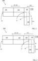
- the manufacturing machine 100 comprises two feeding units 101 and 102, a processing unit 103, a forming unit 104 and a switching unit 110.
- the two feeding units 101 and 102 are each configured to feed a respective web material M, which is the same.
- the feeding units 101 and/or 102 can also act as a storage unit of the material M.
- the web material M is the same but a transporting support 105 or 106, on which the web material M is arranged, is different as disclosed in detail below.
- the fed web material M is illustrated as a line. It is understood that the fed web material M has dimensions (in particular thickness and depth; both measured orthogonal to its longitudinal extension L) which, on the contrary as illustrated, are not null.
- the processing unit 103 is configured to receive the web material M from the feeding unit 101 or 102 and to process the web material M.
- the processing unit 103 is configured to subject the material M to treatments in preparation of its gathering for forming the continuous material strand (as disclosed in detail below).
- the processing unit 103 comprises a crimping device (of known type and not further described or illustrated).
- the crimping device is configured to provide the web material M with material weakenings, which are configured to promote the subsequent gathering of the material M in the forming unit 104.
- the material weakenings comprise: a plurality of folds and/or a plurality of cuts and/or incisions.
- the plurality of fold and/or the plurality of cuts and/or incisions extend parallel to the longitudinal extension of the material M or are arranged according to a predetermined pattern.
- the cuts and/or incisions extend continuously or intermittently along the longitudinal or transversal extension of the material M.
- the forming unit 104 is arranged downstream to the processing unit 103.
- the forming unit 104 is configured to receive the web material M from the processing unit 103 and to form a continuous material strand by gathering the web material M.
- the forming unit 104 comprises a forming device configured to form a continuous material strand by gathering the web material M received by the processing unit 103.
- the forming device is of the known type and comprises a forming beam configured to gather the web material M which passes into it and preferably to wrap the continuous material strand with a paper strip so as to achieve a wrapped continuous material strand.
- the web material M is moved longitudinally along an advancing path AP defined between an inlet station SI (arranged downstream of each feeding units 101 and 102 and upstream of the processing unit 103) in correspondence of which the web material M enters in the manufacturing machine 100 and an outlet station SO of the forming unit 104 in correspondence of which the continuous material strand exits from the manufacturing machine 100.
- the advancing path AP defines an advancing direction AD of the web material M.
- the feeding unit 101 is configured to feed the web material M along a feeding direction FD1 drawn it from at least one stack 1.
- the feeding unit 101 comprises a first transport support 105 on which the web material M is stacked on at least one stack 1 (as schematically illustrated in figure 5 ).
- the web material M comprises a plurality of folds defined by folding lines 3 which extends transversally, in particular orthogonally, to the longitudinal extension of the web material M. Each fold is made in alternating opposite folding directions FD, so that two subsequent layers obtained by folding the web material M are parallel to each other. In other words, the material M, is "zig-zag" folded. Two subsequent layers obtained by folding the material M are superimposed on top of each other ( figures 5 and 6 ).
- the stacks 1 are arranged on the transport structure 105 configured to be fed to the manufacturing machine 100 of the tobacco industry.
- the transport structure 105 is fed to the manufacturing machine 100 through a conveying unit 107 (illustrated schematically in figure 6 ).
- the longitudinal extension of the web material is parallel to the feeding direction FD1.
- the feeding unit 102 is configured to feed the web material M along a feeding direction FD2 drawn it from a bobbin.
- the feeding unit 102 comprises a transporting support 106 on which is arranged the bobbin of the web material M.
- the transporting support 106 is rotatable around a rotation axis transversal, in particular orthogonal, to the second feeding direction FD2.
- the transporting support 106 is a different type from the transporting support 105.
- the transport support 105 being a pallet (also known as skid or storage rack). While the transport support 106 being a shaft for the bobbin (the web material M is wound neatly on a core).
- the manufacturing machine 100 comprises the switching unit 110 configured to switch selectively from the feeding unit 101 to the feeding unit 102; and vice versa. Therefore, the manufacturing machine 100 is configured for selectively produce the material strand with the web material M fed by the feeding unit 101 or the feeding unit 102.
- the web material M fed by the feeding units 101 and 102 is of the same type but stored differently. In other words, the transporting supports 105 and 106 are different. In other words, what is different between the material M fed by the two feeding units 101 and 102 is not the material M per se but is the transport support on which it is arranged.
- the switching unit 110 is an interface (in particular an input interface or an input-output interface) through which an operator can select which feeding unit 101 or 102 activate for feeding the material M on the respective transporting support 105 or 106 to the processing unit 103.
- the web material M comprises at least one material chosen between: paper, cellulose, non-woven material, tobacco, a substrate for the aerosol formation or a combination of them.
- the feeding unit 101 is arranged parallel to the processing unit 103 so that a feeding direction FD1 of the feeding unit 101 is parallel, in particular aligned, to the advancing direction AD; while the feeding unit 102 is arranged transversally, in particular orthogonally, to the processing unit 103 so that a feeding direction FD2 of the feeding unit 102 is transversally, in particular orthogonally, to the advancing direction AD.
- the feeding unit 101 is arranged so that the feeding direction FD1 is parallel to the advancing direction AD. Furthermore, the feeding unit 102 is arranged so that the feeding direction FD2 is transversal, in particular orthogonal, to the advancing direction AD.
- the manufacturing machine 100 comprises a buffer 108 (optional) arranged between the processing unit 103 and the feeding units 101 and 102.
- the buffer 108 is arranged aligned with the processing unit 103.
- the feeding unit 101 is arranged upstream (with reference to the feeding directions FD1 and FD2) to the feeding unit 102, so that the feeding unit 101 is closer to the processing unit 103 than the feeding unit 102.
- the feeding unit 101 is arranged downstream (with reference to the feeding directions FD1 and FD2) to the feeding unit 102, so that the feeding unit 102 is closer to the processing unit 103 than the feeding unit 101.
- both feeding units 101 and 102 are arranged transversally, in particular orthogonally, to the processing unit 103, so that both feeding directions FD1 and FD2 of the feeding units 101 and 102 are transversally, in particular orthogonally, to the advancing direction AD.
- the feeding unit 101 is arranged so that the first feeding direction FD1 is transversal, in particular orthogonal, to the advancing direction AD and the feeding unit 102 is arranged so that the feeding direction FD2 is transversal, in particular orthogonal, to the advancing direction AD.
- the feeding unit 101 is arranged downstream (with reference to the feeding directions FD1 and FD2) to the feeding unit 102, so that the feeding unit 102 is closer to the processing unit 103 than the feeding unit 101.
- the feeding unit 101 is arranged upstream (with reference to the feeding directions FD1 and FD2) to the feeding unit 102, so that the feeding unit 101 is closer to the processing unit 103 than the feeding unit 102.
- the arrangement of the feeding units 101, 102, the processing unit 103 and the forming unit 104 showed in figures 1, 2 , 3 is particularly advantageous. In particular, those arrangements allow to have a manufacturing machine 100 that takes up limited space.
- the manufacturing machine 100 comprising a guiding member 109 arranged between the processing unit 103 and both feeding units 101 and 102.
- the guiding member 109 is configured to guide the web material M during the direction change from an orthogonal orientation to the advancing direction AD to a parallel orientation to the advancing direction AD.
- the web material M fed by the feeding unit 101 is fed at a height from the floor (namely the dimension measured orthogonal to the floor on which the manufacturing machine 100 is arranged) which is higher than a height (measured in the same way) at which the web material M is fed by the feeding unit 102.
- the invention described so far comprises a plurality of advantages.
- the switching unit 110 to switch selectively from one feeding unit 101 to the other feeding unit 102, or vice versa, in an easy way, without requiring any effort.
- the invention can also be easily implemented in pre-existing machines 100 without requiring major adaptation interventions, but simply by adding the feeding unit 101 or 102 and eventually the switching unit 110.
Landscapes
- Cigarettes, Filters, And Manufacturing Of Filters (AREA)
Priority Applications (1)
| Application Number | Priority Date | Filing Date | Title |
|---|---|---|---|
| EP23205430.4A EP4544923A1 (fr) | 2023-10-24 | 2023-10-24 | Machine de fabrication pour produire un brin de matériau pour un article à fumer |
Applications Claiming Priority (1)
| Application Number | Priority Date | Filing Date | Title |
|---|---|---|---|
| EP23205430.4A EP4544923A1 (fr) | 2023-10-24 | 2023-10-24 | Machine de fabrication pour produire un brin de matériau pour un article à fumer |
Publications (1)
| Publication Number | Publication Date |
|---|---|
| EP4544923A1 true EP4544923A1 (fr) | 2025-04-30 |
Family
ID=88511128
Family Applications (1)
| Application Number | Title | Priority Date | Filing Date |
|---|---|---|---|
| EP23205430.4A Pending EP4544923A1 (fr) | 2023-10-24 | 2023-10-24 | Machine de fabrication pour produire un brin de matériau pour un article à fumer |
Country Status (1)
| Country | Link |
|---|---|
| EP (1) | EP4544923A1 (fr) |
Citations (5)
| Publication number | Priority date | Publication date | Assignee | Title |
|---|---|---|---|---|
| GB793114A (en) * | 1955-08-09 | 1958-04-09 | Peter Henry Julian Byk | Improvements in or relating to filter plugs or wads |
| EP2046154B1 (fr) * | 2006-08-02 | 2011-11-23 | R.J. Reynolds Tobacco Company | Équipement et procédé associé d'insertion de matériaux dans des filtres à cigarette |
| DE202010018573U1 (de) * | 2009-08-18 | 2017-10-11 | G. D Societa' Per Azioni | Maschine zum gleichzeitigen Produzieren wenigstens zweier Zigarettenfilterstangen |
| WO2020142005A1 (fr) * | 2018-12-31 | 2020-07-09 | Ysq International Pte. Ltd. | Appareil et procédé de production d'un élément filtre |
| US20230180820A1 (en) * | 2020-05-19 | 2023-06-15 | International Tobacco Machinery Poland Sp. Z O. O. | Apparatus and method for manufacturing a roll of crimped filling material for rod-like articles |
-
2023
- 2023-10-24 EP EP23205430.4A patent/EP4544923A1/fr active Pending
Patent Citations (5)
| Publication number | Priority date | Publication date | Assignee | Title |
|---|---|---|---|---|
| GB793114A (en) * | 1955-08-09 | 1958-04-09 | Peter Henry Julian Byk | Improvements in or relating to filter plugs or wads |
| EP2046154B1 (fr) * | 2006-08-02 | 2011-11-23 | R.J. Reynolds Tobacco Company | Équipement et procédé associé d'insertion de matériaux dans des filtres à cigarette |
| DE202010018573U1 (de) * | 2009-08-18 | 2017-10-11 | G. D Societa' Per Azioni | Maschine zum gleichzeitigen Produzieren wenigstens zweier Zigarettenfilterstangen |
| WO2020142005A1 (fr) * | 2018-12-31 | 2020-07-09 | Ysq International Pte. Ltd. | Appareil et procédé de production d'un élément filtre |
| US20230180820A1 (en) * | 2020-05-19 | 2023-06-15 | International Tobacco Machinery Poland Sp. Z O. O. | Apparatus and method for manufacturing a roll of crimped filling material for rod-like articles |
Similar Documents
| Publication | Publication Date | Title |
|---|---|---|
| CN1075444C (zh) | 复合条带的形成方法 | |
| US3948504A (en) | Method and apparatus for forming and collating printed signatures | |
| CN104768404B (zh) | 香烟制造组装机以及相关的组装方法 | |
| GB2282800A (en) | Processing webs of packaging blank material | |
| JPH01150660A (ja) | ロール切断機 | |
| ITFI20130046A1 (it) | "macchina ribobinatrice e metodo per la produzione di rotoli di materiale nastriforme" | |
| CN111519302A (zh) | 和纸线制造装置及和纸线制造方法 | |
| JP6959382B2 (ja) | ペーパーロールの製造方法及びプラント | |
| EP4544923A1 (fr) | Machine de fabrication pour produire un brin de matériau pour un article à fumer | |
| ITFI20010121A1 (it) | Polmone di accumulo per prodotti allungati,come tubi od altro | |
| RU2739953C2 (ru) | Способ и устройство для изготовления рулона из тестовой заготовки и разделительного листа | |
| EP4545457A1 (fr) | Machine de fabrication pour produire un brin de matériau pour un article à fumer et procédé associé | |
| JPH07304121A (ja) | ブランクを保管する方法及び装置 | |
| US5915301A (en) | Upper folder drive roll arrangement | |
| US20240217767A1 (en) | Slitter-winder and a Method for Slitting and Winding a Fiber Web | |
| EP4544922A1 (fr) | Machine de fabrication pour produire un brin de matériau pour un article à fumer et procédé associé | |
| EP4585063A1 (fr) | Machine de fabrication pour produire un brin de matériau pour un article à fumer et procédé associé | |
| CN102666330A (zh) | 用于制造和加工薄片堆叠特别是纸张堆叠的设备 | |
| EP1232110B1 (fr) | Ensemble d'emballage | |
| CN105451980B (zh) | 一种生产包装一片或一摞瓷砖的纸箱的机器 | |
| KR20140104749A (ko) | 관형상의 부직포 필터 제조장치 | |
| WO2025196608A1 (fr) | Appareil et procédé de chargement en continu d'un matériau laminaire dans une machine de traitement | |
| CN101541654A (zh) | 纤维幅材机的分切卷绕机 | |
| JP4881151B2 (ja) | 片面ダンボール紙の製造装置 | |
| EP2664567B1 (fr) | Procédé de guidage de bande dans un enrouleuse-refendeuse et une machine enrouleuse-refendeuse |
Legal Events
| Date | Code | Title | Description |
|---|---|---|---|
| PUAI | Public reference made under article 153(3) epc to a published international application that has entered the european phase |
Free format text: ORIGINAL CODE: 0009012 |
|
| STAA | Information on the status of an ep patent application or granted ep patent |
Free format text: STATUS: THE APPLICATION HAS BEEN PUBLISHED |
|
| AK | Designated contracting states |
Kind code of ref document: A1 Designated state(s): AL AT BE BG CH CY CZ DE DK EE ES FI FR GB GR HR HU IE IS IT LI LT LU LV MC ME MK MT NL NO PL PT RO RS SE SI SK SM TR |
|
| STAA | Information on the status of an ep patent application or granted ep patent |
Free format text: STATUS: REQUEST FOR EXAMINATION WAS MADE |
|
| 17P | Request for examination filed |
Effective date: 20250714 |
|
| R17P | Request for examination filed (corrected) |
Effective date: 20250714 |
|
| GRAP | Despatch of communication of intention to grant a patent |
Free format text: ORIGINAL CODE: EPIDOSNIGR1 |
|
| STAA | Information on the status of an ep patent application or granted ep patent |
Free format text: STATUS: GRANT OF PATENT IS INTENDED |
|
| INTG | Intention to grant announced |
Effective date: 20251112 |
|
| P01 | Opt-out of the competence of the unified patent court (upc) registered |
Free format text: CASE NUMBER: UPC_APP_0017103_4544923/2025 Effective date: 20251211 |
|
| GRAS | Grant fee paid |
Free format text: ORIGINAL CODE: EPIDOSNIGR3 |
|
| GRAA | (expected) grant |
Free format text: ORIGINAL CODE: 0009210 |
|
| STAA | Information on the status of an ep patent application or granted ep patent |
Free format text: STATUS: THE PATENT HAS BEEN GRANTED |