EP4544965A2 - Dispositif pour boire - Google Patents
Dispositif pour boire Download PDFInfo
- Publication number
- EP4544965A2 EP4544965A2 EP25163819.3A EP25163819A EP4544965A2 EP 4544965 A2 EP4544965 A2 EP 4544965A2 EP 25163819 A EP25163819 A EP 25163819A EP 4544965 A2 EP4544965 A2 EP 4544965A2
- Authority
- EP
- European Patent Office
- Prior art keywords
- drinking
- aroma
- air
- liquid
- container
- Prior art date
- Legal status (The legal status is an assumption and is not a legal conclusion. Google has not performed a legal analysis and makes no representation as to the accuracy of the status listed.)
- Pending
Links
Images


Classifications
-
- A—HUMAN NECESSITIES
- A47—FURNITURE; DOMESTIC ARTICLES OR APPLIANCES; COFFEE MILLS; SPICE MILLS; SUCTION CLEANERS IN GENERAL
- A47G—HOUSEHOLD OR TABLE EQUIPMENT
- A47G19/00—Table service
- A47G19/12—Vessels or pots for table use
-
- B—PERFORMING OPERATIONS; TRANSPORTING
- B65—CONVEYING; PACKING; STORING; HANDLING THIN OR FILAMENTARY MATERIAL
- B65D—CONTAINERS FOR STORAGE OR TRANSPORT OF ARTICLES OR MATERIALS, e.g. BAGS, BARRELS, BOTTLES, BOXES, CANS, CARTONS, CRATES, DRUMS, JARS, TANKS, HOPPERS, FORWARDING CONTAINERS; ACCESSORIES, CLOSURES, OR FITTINGS THEREFOR; PACKAGING ELEMENTS; PACKAGES
- B65D51/00—Closures not otherwise provided for
- B65D51/24—Closures not otherwise provided for combined or co-operating with auxiliary devices for non-closing purposes
-
- B—PERFORMING OPERATIONS; TRANSPORTING
- B65—CONVEYING; PACKING; STORING; HANDLING THIN OR FILAMENTARY MATERIAL
- B65D—CONTAINERS FOR STORAGE OR TRANSPORT OF ARTICLES OR MATERIALS, e.g. BAGS, BARRELS, BOTTLES, BOXES, CANS, CARTONS, CRATES, DRUMS, JARS, TANKS, HOPPERS, FORWARDING CONTAINERS; ACCESSORIES, CLOSURES, OR FITTINGS THEREFOR; PACKAGING ELEMENTS; PACKAGES
- B65D47/00—Closures with filling and discharging, or with discharging, devices
- B65D47/04—Closures with discharging devices other than pumps
- B65D47/06—Closures with discharging devices other than pumps with pouring spouts or tubes; with discharge nozzles or passages
- B65D47/065—Closures with discharging devices other than pumps with pouring spouts or tubes; with discharge nozzles or passages with hinged, foldable or pivotable spouts
-
- A—HUMAN NECESSITIES
- A47—FURNITURE; DOMESTIC ARTICLES OR APPLIANCES; COFFEE MILLS; SPICE MILLS; SUCTION CLEANERS IN GENERAL
- A47G—HOUSEHOLD OR TABLE EQUIPMENT
- A47G19/00—Table service
- A47G19/22—Drinking vessels or saucers used for table service
- A47G19/2205—Drinking glasses or vessels
-
- A—HUMAN NECESSITIES
- A47—FURNITURE; DOMESTIC ARTICLES OR APPLIANCES; COFFEE MILLS; SPICE MILLS; SUCTION CLEANERS IN GENERAL
- A47G—HOUSEHOLD OR TABLE EQUIPMENT
- A47G21/00—Table-ware
- A47G21/18—Drinking straws or the like
- A47G21/183—Drinking straws or the like with means for changing the flavour of the liquid
-
- B—PERFORMING OPERATIONS; TRANSPORTING
- B65—CONVEYING; PACKING; STORING; HANDLING THIN OR FILAMENTARY MATERIAL
- B65D—CONTAINERS FOR STORAGE OR TRANSPORT OF ARTICLES OR MATERIALS, e.g. BAGS, BARRELS, BOTTLES, BOXES, CANS, CARTONS, CRATES, DRUMS, JARS, TANKS, HOPPERS, FORWARDING CONTAINERS; ACCESSORIES, CLOSURES, OR FITTINGS THEREFOR; PACKAGING ELEMENTS; PACKAGES
- B65D23/00—Details of bottles or jars not otherwise provided for
- B65D23/12—Means for the attachment of smaller articles
-
- B—PERFORMING OPERATIONS; TRANSPORTING
- B65—CONVEYING; PACKING; STORING; HANDLING THIN OR FILAMENTARY MATERIAL
- B65D—CONTAINERS FOR STORAGE OR TRANSPORT OF ARTICLES OR MATERIALS, e.g. BAGS, BARRELS, BOTTLES, BOXES, CANS, CARTONS, CRATES, DRUMS, JARS, TANKS, HOPPERS, FORWARDING CONTAINERS; ACCESSORIES, CLOSURES, OR FITTINGS THEREFOR; PACKAGING ELEMENTS; PACKAGES
- B65D47/00—Closures with filling and discharging, or with discharging, devices
- B65D47/04—Closures with discharging devices other than pumps
- B65D47/06—Closures with discharging devices other than pumps with pouring spouts or tubes; with discharge nozzles or passages
-
- B—PERFORMING OPERATIONS; TRANSPORTING
- B65—CONVEYING; PACKING; STORING; HANDLING THIN OR FILAMENTARY MATERIAL
- B65D—CONTAINERS FOR STORAGE OR TRANSPORT OF ARTICLES OR MATERIALS, e.g. BAGS, BARRELS, BOTTLES, BOXES, CANS, CARTONS, CRATES, DRUMS, JARS, TANKS, HOPPERS, FORWARDING CONTAINERS; ACCESSORIES, CLOSURES, OR FITTINGS THEREFOR; PACKAGING ELEMENTS; PACKAGES
- B65D47/00—Closures with filling and discharging, or with discharging, devices
- B65D47/04—Closures with discharging devices other than pumps
- B65D47/20—Closures with discharging devices other than pumps comprising hand-operated members for controlling discharge
- B65D47/26—Closures with discharging devices other than pumps comprising hand-operated members for controlling discharge with slide valves, i.e. valves that open and close a passageway by sliding over a port, e.g. formed with slidable spouts
- B65D47/261—Closures with discharging devices other than pumps comprising hand-operated members for controlling discharge with slide valves, i.e. valves that open and close a passageway by sliding over a port, e.g. formed with slidable spouts having a rotational or helicoidal movement
- B65D47/265—Closures with discharging devices other than pumps comprising hand-operated members for controlling discharge with slide valves, i.e. valves that open and close a passageway by sliding over a port, e.g. formed with slidable spouts having a rotational or helicoidal movement between planar parts
-
- B—PERFORMING OPERATIONS; TRANSPORTING
- B65—CONVEYING; PACKING; STORING; HANDLING THIN OR FILAMENTARY MATERIAL
- B65D—CONTAINERS FOR STORAGE OR TRANSPORT OF ARTICLES OR MATERIALS, e.g. BAGS, BARRELS, BOTTLES, BOXES, CANS, CARTONS, CRATES, DRUMS, JARS, TANKS, HOPPERS, FORWARDING CONTAINERS; ACCESSORIES, CLOSURES, OR FITTINGS THEREFOR; PACKAGING ELEMENTS; PACKAGES
- B65D47/00—Closures with filling and discharging, or with discharging, devices
- B65D47/04—Closures with discharging devices other than pumps
- B65D47/20—Closures with discharging devices other than pumps comprising hand-operated members for controlling discharge
- B65D47/30—Closures with discharging devices other than pumps comprising hand-operated members for controlling discharge with plug valves, i.e. valves that open and close a passageway by turning a cylindrical or conical plug without axial passageways
- B65D47/305—Closures with discharging devices other than pumps comprising hand-operated members for controlling discharge with plug valves, i.e. valves that open and close a passageway by turning a cylindrical or conical plug without axial passageways provided with a spout, e.g. "escargot"-type valve
-
- B—PERFORMING OPERATIONS; TRANSPORTING
- B65—CONVEYING; PACKING; STORING; HANDLING THIN OR FILAMENTARY MATERIAL
- B65D—CONTAINERS FOR STORAGE OR TRANSPORT OF ARTICLES OR MATERIALS, e.g. BAGS, BARRELS, BOTTLES, BOXES, CANS, CARTONS, CRATES, DRUMS, JARS, TANKS, HOPPERS, FORWARDING CONTAINERS; ACCESSORIES, CLOSURES, OR FITTINGS THEREFOR; PACKAGING ELEMENTS; PACKAGES
- B65D77/00—Packages formed by enclosing articles or materials in preformed containers, e.g. boxes, cartons, sacks or bags
- B65D77/22—Details
- B65D77/225—Pressure relief-valves incorporated in a container wall, e.g. valves comprising at least one elastic element
-
- B—PERFORMING OPERATIONS; TRANSPORTING
- B65—CONVEYING; PACKING; STORING; HANDLING THIN OR FILAMENTARY MATERIAL
- B65D—CONTAINERS FOR STORAGE OR TRANSPORT OF ARTICLES OR MATERIALS, e.g. BAGS, BARRELS, BOTTLES, BOXES, CANS, CARTONS, CRATES, DRUMS, JARS, TANKS, HOPPERS, FORWARDING CONTAINERS; ACCESSORIES, CLOSURES, OR FITTINGS THEREFOR; PACKAGING ELEMENTS; PACKAGES
- B65D85/00—Containers, packaging elements or packages, specially adapted for particular articles or materials
- B65D85/70—Containers, packaging elements or packages, specially adapted for particular articles or materials for materials not otherwise provided for
- B65D85/72—Containers, packaging elements or packages, specially adapted for particular articles or materials for materials not otherwise provided for for edible or potable liquids, semiliquids, or plastic or pasty materials
-
- A—HUMAN NECESSITIES
- A47—FURNITURE; DOMESTIC ARTICLES OR APPLIANCES; COFFEE MILLS; SPICE MILLS; SUCTION CLEANERS IN GENERAL
- A47G—HOUSEHOLD OR TABLE EQUIPMENT
- A47G19/00—Table service
- A47G19/12—Vessels or pots for table use
- A47G2019/122—Vessels or pots for table use for holding and dispensing a plurality of different liquids
-
- A—HUMAN NECESSITIES
- A47—FURNITURE; DOMESTIC ARTICLES OR APPLIANCES; COFFEE MILLS; SPICE MILLS; SUCTION CLEANERS IN GENERAL
- A47G—HOUSEHOLD OR TABLE EQUIPMENT
- A47G2400/00—Details not otherwise provided for in A47G19/00-A47G23/16
- A47G2400/04—Influencing taste or nutritional properties
-
- B—PERFORMING OPERATIONS; TRANSPORTING
- B65—CONVEYING; PACKING; STORING; HANDLING THIN OR FILAMENTARY MATERIAL
- B65D—CONTAINERS FOR STORAGE OR TRANSPORT OF ARTICLES OR MATERIALS, e.g. BAGS, BARRELS, BOTTLES, BOXES, CANS, CARTONS, CRATES, DRUMS, JARS, TANKS, HOPPERS, FORWARDING CONTAINERS; ACCESSORIES, CLOSURES, OR FITTINGS THEREFOR; PACKAGING ELEMENTS; PACKAGES
- B65D2203/00—Decoration means, markings, information elements, contents indicators
- B65D2203/12—Audible, olfactory or visual signalling means
-
- B—PERFORMING OPERATIONS; TRANSPORTING
- B65—CONVEYING; PACKING; STORING; HANDLING THIN OR FILAMENTARY MATERIAL
- B65D—CONTAINERS FOR STORAGE OR TRANSPORT OF ARTICLES OR MATERIALS, e.g. BAGS, BARRELS, BOTTLES, BOXES, CANS, CARTONS, CRATES, DRUMS, JARS, TANKS, HOPPERS, FORWARDING CONTAINERS; ACCESSORIES, CLOSURES, OR FITTINGS THEREFOR; PACKAGING ELEMENTS; PACKAGES
- B65D2547/00—Closures with filling and discharging, or with discharging, devices
- B65D2547/04—Closures with discharging devices other than pumps
- B65D2547/06—Closures with discharging devices other than pumps with pouring spouts ot tubes; with discharge nozzles or passages
- B65D2547/063—Details of spouts
Definitions
- the invention relates to a drinking device for the retronasal intake of an aroma substance.
- a first step to solve the problem is to add the flavoring to a beverage immediately before consumption.
- US 2008/028353 A1 , US 2015/030726 A1 as well as the US 8,662,2904 are examples of dosing systems in which a flavoring substance originally intended for separate use is added to and dissolved in the drinking liquid immediately before or during consumption. While this measure can avoid problems such as stabilizing the drinking liquid over an extended period, the problem of unwanted ingestion of additives remains.
- the drinking vessel after the US 8,662,339 B2 works on the principle that an aroma is inhaled through the nose while drinking.
- the invention is based on the object of proposing a drinking device that provides the user with an improved taste experience.
- the key aspect of the drinking device according to the invention is that the aroma substance is absorbed retronasally.
- the aroma substance enters the user's mouth together with the drinking liquid during drinking and then rises retronasally through the pharynx to the olfactory mucosa (regio olfactoria), where it is detected by the receptors located there and perceived by the user.
- the device according to the invention is equally suitable for cold or warm drinking liquids.
- a person's sense of taste is essentially shaped by the retronasal sense of smell.
- the receptors in the tongue can only distinguish between sweet, sour, bitter, salty, and umami, whereas the differentiated sense of taste arises when the gaseous phase of food and liquids in the throat rises via the retronasal pathway and reaches the olfactory mucosa.
- the sensors located there trigger neurological stimuli that create a taste impression in the brain.
- a person who is thus introduced to an aroma in the throat while drinking gets the impression that the beverage is flavored, because during retronasal smelling the brain perceives the beverage as the source of the aroma, even though the user is consuming a pure, unflavored, pure liquid, such as water.
- the storage container which is preferably designed to be refillable, can hold pure water or carbonated water, while the aroma substance is transferred to the air in the transport channel and added to the drinking liquid immediately before it is consumed by the user or transported separately into the user's throat.
- the drinking liquid can also have its own flavor.
- the existing flavor of the drinking liquid is either enhanced by the flavoring substance from the flavor container or supplemented by one or more additional flavor components.
- apple juice is present in the storage container
- apple flavoring can be added to enhance the taste experience, or orange flavoring, for example, can be added to create a flavor blend.
- alcoholic beverages such as beer can also be provided with additional flavoring substances, whereby the specific preferences of a user can be catered to by using a corresponding flavor container in the drinking device according to the invention.
- flavors not commonly used in the food sector can also be used in the drinking device disclosed here, such as "sandalwood,” “spring meadow,” or "unicorn,” which are well-known in room fragrances.
- the flavor used can be artificial or natural. It is possible to use flavors that have been isolated or enriched from an artificial or natural source, as well as natural substances, such as fresh or processed products made from, for example, lemon peel, dandelion leaves, licorice or other aromatic substances.
- multiple aroma containers can also be provided.
- This can be a spare aroma container that can be used as soon as the aroma container in use is exhausted.
- it is also possible, alternatively or additionally, to use multiple aroma containers that are in use simultaneously in order to create any desired aroma mixtures from different base aromas.
- the transport channel for drinking liquid runs to the mouth end, while the air channel either opens into the transport channel for drinking liquid in the immediate vicinity of the mouth end, or runs separately from the transport channel for drinking liquid to the mouth end.
- the mouthpiece is designed such that the transport channel for drinking liquid and the air channel for transporting flavored air extend longitudinally at the mouthpiece separately from one another and essentially the same distance.
- “Longitudinal direction” refers to the longitudinal direction of the transport channel for drinking liquid and the air channel for transporting flavored air at the mouthpiece. In other words, when drinking, the transport channel for drinking liquid and the air channel extend essentially the same distance into the user's oral cavity.
- the flavored air and the drinking liquid are sucked separately from the drinking device.
- the flavored air does not have to escape from the surrounding drinking liquid in the form of air bubbles, but can rise retronasally via the pharynx to the olfactory mucosa immediately after entering the oral cavity.
- a further advantage of supplying the flavored air and the drinking liquid separately into the oral cavity is that there is even less mass transfer between the air and the drinking liquid. There are two reasons for this. The first reason is that the flavored air is not contained in the drinking liquid in the form of small bubbles, meaning there is a significantly smaller total surface area available for mass transfer between the liquid phase and the gaseous phase.
- a variant of the solution according to the invention consists in that the mouth end is designed in such a way that when the drinking device is used, the transport channel for drinking liquid and the air channel for transporting flavored air extend to different distances into the user's mouth.
- the air duct for transporting flavored air can extend further into the user's mouth than the transport duct for drinking liquid, or the transport duct for drinking liquid can extend further into the user's mouth.
- Both solutions have in common that the flavored air and the drinking liquid are sucked out of the device separately.
- Both variants also have in common that the exchange of substances between the flavored air and the drinking liquid is kept as low as possible. This advantage can be achieved in the same way if the transport duct for drinking liquid and the air duct for transporting flavored air extend the same distance into the user's mouth, but are both designed in such a way that they protrude into the user's mouth when used as intended. An extension too far into the mouth is perceived as unpleasant by the user.
- the technical challenge of all the solutions described above is to coordinate the geometries of the transport channel for the drinking liquid and the air channel in such a way that, depending on the drinking position and, in the case of special drinking liquids and also the viscosity of the drinking liquid, the flavored air and the drinking liquid are sucked in in the desired ratio to each other.
- the drinking device further comprises a throttling device and/or sealing device for the transport channel for drinking liquid and/or the air channel for transporting flavored air, wherein the sealing device is preferably provided in a mouthpiece surrounding the mouth end and the mouthpiece is movable from a sealing position to a non-sealing position.
- a throttling device can be provided as an alternative to a sealing device, but preferably in addition to a sealing device.
- a throttling device makes it possible to adjust the ratio between drinking liquid and flavored air, which, for example, allows the degree of flavoring or the flow rate of drinking liquid to be adjusted.
- a simple embodiment of a throttling device, which can be actuated until complete sealing is achieved, is a squeezing device, with the aid of which a flexible section of the transport channel or air channel can be reduced in terms of its internal cross-section or completely clamped off.
- a preferred alternative embodiment of the sealing device is the provision of a pull-tap, preferably located on the mouthpiece, which is pulled out by the user to open the flow. After drinking, the pull-tap is pushed back toward the mouthpiece to close the air channel and the transport channel.
- Another preferred alternative to the drinking device according to the invention comprises a rotary plug, which is opened or closed by the user by turning it.
- rotary plugs are well known in chemical engineering, as a rotary plug represents a simple but very tightly sealed component.
- a rotary plug can also be continuously adjusted, so that a rotary plug combines the functions of a throttling device and a shut-off device.
- Another preferred alternative of the device according to the invention comprises a sliding valve, which, according to a preferred variant, is provided in a lid of the drinking device and can simultaneously contain the mouthpiece.
- a sliding valve which, according to a preferred variant, is provided in a lid of the drinking device and can simultaneously contain the mouthpiece.
- a preferred alternative embodiment of the device is the provision of a twist-on lid, which is either placed on or screwed on, thereby sealing the drinking device.
- a twist-on lid is well suited to tightly closing the drinking device even when increased pressure builds up inside the storage container, as can occur when the drinking liquid is a carbonated beverage.
- Such a lid can tightly close both the transport channel for drinking liquid and the air channel for flavored air, but also an additional air line for supplying air into the interior of the storage container for the purpose of pressure equalization.
- a further advantage of a twist-on lid is that it protects the mouthpiece from contamination and is a familiar element to every user, whose suitability for tightly closing the drinking device is trusted.
- a preferred alternative embodiment of the device is the provision of a sports valve, as is known from drinking bottles, for example, for cycling. Accordingly, the function of a sports valve is known, so that the user intuitively pulls the valve to drink and pushes it back into its original position after drinking.
- the embodiment in which the mouthpiece of the drinking device simultaneously functions as a shut-off device is particularly preferred, allowing all transport paths leading toward the mouthpiece to be tightly closed.
- the mouthpiece is designed such that it can be moved from the sealing position to the non-sealing position via a translational movement.
- the mouthpiece can be designed such that both the transport channel for drinking liquid and the air channel, as well as the air line for air flow into the interior of the storage container, can be sealed and opened. Consequently, the user only needs to move the mouthpiece into an operating position, which activates the sealing device unnoticed by the user. This allows the number of components to be kept to a minimum, which, among other things, enables a more hygienic design and also saves costs in the production and assembly of the drinking system.
- the at least one aroma container is removable and can be inserted into the drinking device according to the invention with the aid of a simple movement sequence.
- a bayonet closure can be used.
- a bayonet closure has the advantage that, after insertion, the correct orientation of the aroma container in the drinking device is ensured.
- a spring element can additionally be provided which allows the aroma container to emerge from its receptacle as soon as the aroma container has not been inserted correctly.
- different locking positions can be used to preselect between different aroma intensity settings.
- one of the at least one aroma container comprises a sealing device, wherein the aroma container is movable from a sealing position to a non-sealing position.
- a aroma container with a substantially circular cross-section can be used in the same way as the rotary plug described above, by rotating the aroma container about its axis of symmetry to bring the transport channel for drinking liquid into alignment with the channel through the aroma container. The advantage of this solution is that no additional component is required.
- the aroma container from a sealing position to a non-sealing position by sliding the aroma container in an axial direction.
- an aroma container with any prism-shaped or ring-shaped geometry could be pushed in an axial direction to move the aroma container into a non-sealing position.
- the aroma container can lock into this position, i.e., remain in this position automatically, or drinking with aroma delivery is only possible if the aroma container is held down. In this way, a user could also choose between drinking liquid with or without flavored air.
- At least one of the at least one aroma container can comprise a plurality of chambers containing aroma substances of different odor intensities and/or different odor qualities.
- a plurality of aroma containers can be provided.
- one or more aroma containers can be provided, and this aroma container or any number of the plurality of aroma containers can additionally comprise a plurality of chambers. In this way, any desired variants can be realized. If a single aroma container is provided, it can contain different aromas, so that a different aroma is supplied depending on the direction of insertion or an orientation of the aroma container, which can also be changed by the user during drinking.
- the aroma container allows the type of aroma as well as the aroma strength to be varied.
- an aroma container could contain two, three, or more different aroma intensities of one and the same aroma substance, or a single aroma container could contain two different aromas, each at two different levels, so that the aroma container would have four separate chambers.
- any desired aroma mixture can be created by varying different aroma directions, aroma strengths, or by adding one and the same aroma direction, which can be individually composed by a user.
- one of the at least one aroma container is located in a mouthpiece of the drinking device, wherein the mouthpiece is preferably replaceable.
- the advantage of having the aroma container either integrated into the mouthpiece or attached to a lid of the reservoir is that it allows the user to immediately identify the "flavor.”
- the mouthpiece could be colored according to the selected flavor, such as yellow for a lemon flavor or green for a green apple flavor.
- the storage container for drinking liquid is provided with a lid.
- the lid When the lid is removed, the user has access to both a filling opening for drinking liquid and a receiving opening for one or more aroma containers. After replacing the lid, the user can then vary between different aroma directions by rotating the lid.
- the advantage of this solution is also that no separate locking of the aroma container is required in the drinking device according to the invention, because the aroma container is automatically fixed in the inserted state after the lid is replaced. This solution also makes sealing the aroma container easier.
- an information tab is provided on the aroma container, which protrudes outwards from the drinking vessel after the lid has been put on and informs a user about the inserted
- the tab is easy to grasp to remove the aroma container.
- the aroma container is designed as a ring located near the mouth end of the drinking device.
- a single chamber can be located within the ring.
- the ring-shaped aroma container can contain multiple chambers with different flavors, which are preferably identified for the user by additional marking and/or coloring. In this way, the user can intuitively change the aroma by operating the aroma ring, which can also be done while drinking.
- the use of a aroma container in the shape of a ring offers many options that can be used in a user-friendly manner.
- the drinking device further comprises a pull valve as a pressure equalization valve, which closes an air supply line leading into the interior of the storage container for drinking liquid. If a negative pressure builds up in the storage container due to drinking, i.e., the withdrawal of drinking liquid, the valve opens and allows air to enter the storage container for drinking liquid. As soon as the pressure is equalized, the pressure valve automatically closes again due to its inherent tension, so that no drinking liquid can escape.
- This variant is particularly advantageous in cases in which the shut-off device only closes the transport channel for drinking liquid and the air channel for transporting flavored air, but not the air channel for pressure equalization.
- An exemplary variant of this type is the provision of a mouthpiece that can be pivoted from a sealing position to an operating position, while the air line for pressure equalization is located at a different location in the container.
- the drinking device further comprises a head part which comprises the mouth end and is arranged to be movable relative to the storage container, wherein the head part is movable from a position sealing the transport channel for drinking liquid and/or the air channel to a non-sealing position.
- the head of the drinking device can be pivotally attached to the reservoir for the drinking liquid.
- the geometry of the head relative to the reservoir can be selected such that when the head is rotated into the drinking position, it is angled. This allows the user to adopt an ergonomically comfortable drinking position and also makes it clear to the user that the drinking device is in its ready-to-use state and that improper handling could result in the drinking liquid leaking out. In this way, a drinking device can be designed with a futuristic design language that underscores the claim to be a new and innovative drinking device.
- the drinking device can be designed in a variety of ways. It can be a mobile drinking bottle, which is either single-walled or double-walled as a thermos flask.
- An open drinking vessel similar to a mug, can also be provided, although care must be taken to ensure the correct drinking position so that both the drinking liquid and the aroma to be dosed are directed into the throat when drinking.
- the aroma container could be a ring surrounding the storage container for the drinking liquid and from which the aroma is either dosed into the transport channel for the drinking liquid or supplied to the user via a separate air duct running along the rim of the drinking cup.
- the drinking cup can also be closed at the top and used as a so-called shot glass.
- This variant can be used to modify the taste of drinking liquids such as spirits, liqueurs, or even caffeinated or non-caffeinated beverages with certain flavorings, or to enhance an existing flavor or mask potentially unwanted sensory perceptions.
- a further alternative design consists in integrating the special functional features of the drinking device according to the invention into a straw which contains the mouth end and whose end opposite the mouth end is located in the storage container for drinking liquid.
- the straw is simultaneously the transport channel for the drinking device, running from the storage container to the mouth end of the drinking device.
- the aroma container can be provided in the form of a ring surrounding the straw and located above the level for drinking liquid, so that when the straw is used, air is sucked into the aroma container and is either guided to the mouth end via an air channel running parallel to the transport channel for drinking liquid, or opens into the transport channel for drinking liquid, so that the supplied aroma is metered into the drinking liquid in the form of air bubbles.
- the flavoring substance is delivered through the mouthpiece into the user's mouth and throat, and the taste impression occurs via retronasal absorption of the flavoring substance. Apart from a small, unavoidable amount of absorption of the flavoring substance into the pure drinking liquid, or even the incomplete separation of air bubbles with the flavoring substance from the drinking liquid, the user ingests pure drinking liquid.
- a preferred embodiment of the invention for optimizing or simplifying the drinking device provides that the head part of the drinking device is divisible, dismantled, or foldable.
- the head part can consist of one, two, or more parts that are required for the use of the device. must be put together.
- an essentially axisymmetric division of the head section is possible, so that in the unassembled position the channels of the drinking device are completely or partially open.
- This offers various advantages. Firstly, it makes cleaning the drinking device easier, as the sometimes narrow channels of the device can be easily reached by cleaning fluid and the cleaning fluid is not held back by possible capillary forces.
- a divisible solution for the head section of the drinking device makes it possible to integrate the aroma reservoir of the drinking device into the interior of the head section. In previous systems, the aroma reservoir could only be attached from the outside, which means that it remained visible during use. Previous systems also required a separate fastening mechanism for the aroma reservoir, which can be eliminated with a divisible solution.
- the head part is understood to be the part of the drinking device where the essential technology and/or the aroma reservoir of the drinking device is located. It is preferably mounted on the head of the drinking device, but can also be located elsewhere on the drinking device or integrated into the drinking device.
- the use of a substantially elastic material, such as silicone or other elastomers, for the manufacture of the divisible or non-divisible head section or parts of the head section of the drinking device can facilitate simplified sealing of the system.
- the divisibility of the head section allows for an increased number of connection options between the head section and the liquid reservoir of the drinking device.
- a further preferred embodiment of the invention consists in the channels having a special shape.
- the channel for the liquid it is possible for the channel for the liquid to be widened or tapered at one, two or more points, i.e. the diameter of the channels is larger or smaller than at the other points.
- a tapering or widening can be implemented, for example, in or on the mouthpiece of the drinking device. This enables the user to experience a different mouthfeel when drinking from the drinking device.
- the drinking sensation has been a problem in previous solutions because consumers are not used to drinking liquid together with air bubbles.
- the pressure conditions there change, so that the size and/or shape of the air bubbles in the liquid changes. This improves the user's drinking sensation.
- a further preferred embodiment of the invention is a change in the geometry of the liquid channel at the point where the air channel of the drinking device enters.
- the Venturi effect can be utilized by tapering the liquid channel at the inlet point of the air channel.
- the dynamic pressure back pressure
- the static pressure at its minimum.
- the velocity of the liquid increases in proportion to the cross-sections as it flows through the constricted section, as the volume of liquid remains unchanged.
- the pressure in the air channel which is preferably located at the narrowest point, decreases. This creates a pressure difference that increases the absorption of the flavored air into the liquid in the drinking device. This means that the user, for example, has to suck less forcefully on the drinking device, which improves the drinking experience or results in design advantages.
- a further preferred modification of the geometry of the channels in the drinking device includes different surfaces on the inside of the channels or obstacles that alter the flow conditions in the liquid-carrying channels. Cavitation, among other things, can occur. Cavitation or mechanical fragmentation of the air bubbles can result in a modified air bubble size and/or air bubble geometry. This also improves the drinking experience for the user.
- the change in air bubble size can also be achieved, for example, by using a substantially sieve-like geometry or a membrane.
- the air duct of the drinking device can also have a special shape.
- Previous solutions use a consistently uniformly shaped duct.
- the air duct must have a small diameter, which, on the one hand, creates problems during the production of the head section of the drinking device.
- a narrow duct makes the drinking device more difficult to clean.
- the solution according to the invention therefore provides, for example, that the air duct is tapered essentially only at a short point. This simplifies production and facilitates cleaning.
- a further preferred embodiment of the drinking device according to the invention provides that the aroma unit of the drinking device according to the invention must be activated before use.
- the aroma can initially be micro- or macroscopically encapsulated. Activation can occur, for example, through a change in temperature or a mechanical process.
- a preferred embodiment provides an air-permeable filter in which a substantially round aroma unit is placed, the interior of which essentially contains a fluid comprising a flavoring substance.
- the shell of the aroma unit is preferably made of a material such as gelatin or agarose, so that in the inactive state, a tight shell keeps the fluid with the flavored substance in a non-volatile state. Through activation, for example, by destroying the shell under pressure, the fluid is released into the surrounding filter.
- a further preferred embodiment of the drinking device provides that the air channel comprises a specially shaped chamber.
- This ingress of liquid can, for example, lead to the undesired dilution of the fragrance-releasing substance in the aroma container or to hygiene problems.
- the interruption of the air channel by a chamber can be designed such that a recess is provided in the head section of the drinking device at the contact point between the removable transport channel for drinking liquid and the air channel.
- the air channel coming from the aroma container opens into the chamber at a position substantially at the top.
- the air channel continues at a position substantially at the bottom of the chamber.
- the chamber prevents the drinking liquid from backflowing into the aroma reservoir.
- the essentially opposite position of the continuation of the air duct ensures optimal use of the chamber.
- the different heights of the inlet and outlet openings of the air duct in and out of the chamber allow, among other things, for the drinking liquid to drain back into the drinking device.
- the possible location of the chamber at the contact point between the headpiece and the drinking liquid transport channel facilitates cleaning after disassembling the two components.
- an average air flow through the air channel during normal drinking from the drinking device according to the invention is expediently between approximately 250 and 550 ml/min.
- This air flow is achieved, for example, when using an air channel with a diameter of approximately 0.5 to 2.5 mm or, in the case of a non-circular cross-section, with a cross-sectional area of the air channel between 0.2 mm 2 and 4.9 mm 2 .
- the air flow can also be adjusted in other ways, such as by a substantially short taper of the air channel, a valve, which can also be designed as a check valve to prevent the entry of liquid into the air channel and/or the aroma container, or by the use of a membrane.
- a substantially permeable membrane can, for example, be attached at the mouth of the air channel into the transport channel for drinking liquid. This not only adjusts the air flow to a suitable level, but also adjusts the air bubbles that enter the liquid flow to a desired size, resulting in a more pleasant drinking experience for the drinker.
- Another advantage of using a membrane in this position is that the previously described fluctuations in pressure and Flow conditions at the end of the drinking process do not lead to the entry of drinking liquid into the air duct and/or the aroma container or to its quantity being reduced at this or any other moment.
- a further problem with the drinking device according to the invention lies in sealing the entire drinking device for transport. It should be noted that not only the drinking opening and a pressure equalization channel must be sealed, but also the air channel of the drinking device to prevent drinking liquid from penetrating the aroma container. It would be desirable for the user of the drinking device to be able to close all three openings in a single operation.
- a further preferred embodiment therefore provides for the drinking device to be sealed with a lid that closes all three openings simultaneously. This can preferably be achieved by inserting a pin/spike into at least one of the three openings (each) and sealing any remaining openings using conventional systems.
- a spike/spike can be inserted far enough into the transport channel for drinking liquid to also seal the opening of the air channel into the transport channel for drinking liquid, thus preventing drinking liquid from penetrating the air channel and/or the aroma container.
- Another preferred embodiment which solves the problem of sealing the aroma reservoir described at the beginning of this section, provides that the aroma reservoir is designed, for example, essentially annularly, and that the flow connection between the, for example, removable aroma container and the air duct is severed by a movement such as turning the aroma container upside down.
- the air outlet opening on the aroma container must be arranged off-center, for example, so that an upside-down aroma container closes the aroma-container-side end of the air duct.
- a drinking device 10 is shown schematically, which in the following exemplary embodiment consists of a storage container 12 filled with pure drinking liquid and a head part 14.
- Pure drinking liquid is always understood herein to mean the drinking liquid that does not contain any flavoring added by the drinking system according to the invention.
- the head part 14 has a mouthpiece 16, which in the present case is integrated into the head part, but can also be provided separately, as will be explained later using different embodiments.
- an aroma container 20 Located in the head part 14 is an aroma container 20, which is in flow connection to the ambient air in a manner not shown and from which an air duct 22 leads for transporting flavored air.
- a transport channel 18 for drinking liquid is provided, which in the present exemplary embodiment extends into the pure liquid present in the storage container 12 like a straw.
- the transport channel 18 for drinking liquid and the air channel 22 for transporting flavored air are connected in series, ie the air channel 22 opens into the transport channel for drinking liquid, in which, consequently, in section 18a, there is both the pure liquid sucked in by the user via the mouthpiece 16 and air bubbles with flavored air.
- both the pure liquid and the flavored air are ingested orally.
- the liquid and gas phases separate, and the gaseous flavored air passes through the retronasal pathway 24 in the direction of arrow A to the olfactory mucosa 26.
- the aroma is detected by the receptors located in the olfactory mucosa.
- neuronal processing of the sensory stimuli the user is given the impression that the pure liquid they are drinking (direction of arrow B) has the flavor added by the aroma.
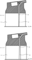
- the arrangement according to Fig. 2 proved to be advantageous.
- the transport channel 18 for drinking liquid and the air channel 22 for transporting flavored air are arranged parallel to each other, ie there is no mixing whatsoever before the mouth end 28.
- the remaining components as well as the operating principle correspond completely to that according to the Fig. 1 schematically illustrated embodiment.
- the mouth end extends a little way into the user's mouth.
- the extension has been exaggerated for clarity.
- the advantage of extending the mouthpiece 28 into the oral cavity is that mixing between the flavored air and the pure liquid is minimized.
- the mouthpiece 28 it is of course also possible for the mouthpiece 28 to be located in the area of the user's lips during intended use.
- the air channel 22 for transporting flavored air and the transport channel 18 for drinking liquid extend the same distance into the user's mouth, i.e., the transport channel 18 and the air channel 22 both end at the same point at the mouth end 28.
- the transport channel 18 and the air channel 22 both end at the same point at the mouth end 28.
- this does not necessarily have to be the case, and one of the two channels can extend less far into the user's mouth than the other. Accordingly, two variants are conceivable.
- the air channel 22 extends further into the oral cavity than the transport channel 18 for the drinking liquid.
- the user has the feeling of taking in the drinking liquid directly through the mouthpiece of the bottle to their lips.
- the flavored air is guided a short distance into the oral cavity and is therefore only in contact with the pure liquid for a very short time, so that mass transfer between the flavored air and the pure liquid can be almost completely ruled out.
- the geometry and length of the individual channels can also be technically determined in order to achieve the most even suction of pure liquid and flavored air during the drinking process.
- only the transport channel 18 for drinking liquid can extend further into the user's oral cavity, while the air channel 22 for transporting flavored air ends in the area of the user's lips when the user drinks from the drinking device according to the invention.
- This measure also serves to keep the contact time between the flavored air and the drinking liquid as short as possible and has the advantage that the aroma can already develop in the user's throat.
- the drinking device In order to use the drinking device according to the invention effectively, it must be ensured that, on the one hand, the aroma does not escape undesirably during storage of the drinking device, but also that a drinking device already filled with pure liquid cannot leak. Furthermore, the drinking device must also have an air channel between the interior of the storage container for the drinking liquid and the outside atmosphere. This air channel serves to equalize pressure and introduces a corresponding volume of air into the drinking device according to the volume of drinking liquid withdrawn from the drinking device during drinking. This air channel should also be equipped with a suitable shut-off device to prevent any unwanted leakage of drinking liquid.
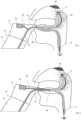
- FIG. 3a and 3b An embodiment is shown in which the mouthpiece is pivotally mounted on the drinking device 10 about a rotation axis 30 and is arranged in the direction of arrow C between the Fig. 3a drinking position shown and the Fig. 3b
- the mouthpiece is provided with a continuation 18b of the transport channel 18 for drinking liquid and a continuation 22b of the air channel 22 for transporting flavored air, which can only be moved in the Fig. 3a shown drinking position are aligned with the channels 18 and 22, so that the user can suck in drinking liquid and flavored air through the mouthpiece 16.
- the closed state as shown in Fig. 3b
- FIGS. 4a and 4b schematically show a possible embodiment of a compensating valve for the air channels 32 for the inflow of air for the purpose of pressure equalization.
- a check valve is used.
- Such a check valve can consist of an elastic component 34 which is firmly fixed in a wall 36 of the drinking device according to the invention and is provided with an elastic sealing plate 38 which, in the case of negative pressure, as in Fig. 4a is shown, deforms under the influence of the increased external pressure so that air can flow through the air duct 32 into the interior of the storage container in the direction of arrow D. If, as in Fig. 4b shown, the pressure equalization is established, the sealing plate 38 lies tightly against the wall 36 from the inside of the container and closes the air channel 32, so that, as shown in Fig. 4b shown, no outside air in direction E into the can flow into the interior of the reservoir 12 and at the same time no liquid can flow out through the air channel 32. If for any reason the pressure inside the reservoir is higher than the pressure of the outside atmosphere, the same situation arises as in Fig. 4b shown and prevents the unwanted escape of liquid or air from the interior of the container.
- the embodiment shown is a variant of the one shown in the Fig. 3a and 3b solution using a rotatable mouthpiece.
- the mouthpiece 16 can be moved in the direction of arrow F and back and is positioned as shown in Fig. 5 is shown, in the drinking position protrudes slightly from the head part 14 of the drinking device 10.
- the mouthpiece 16 which is designed as a slide, it can be provided in a suitable manner on the upper side with a gripping aid in the form of a ribbing (not shown).
- the solution can be Fig. 5 This can be achieved by first extending the transport channels 18 and 20 in the axial direction of the drinking device in the direction of the mouthpiece and only in the Fig. 5 In the extended position of the mouthpiece 16 shown in FIG. 1, the mouthpiece 16 is aligned with the extensions of the transport channels 18 and 22 arranged in the mouthpiece. This could be achieved, for example, by using an eccentric, so that opening and closing is enabled by a rotary movement.
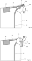
- FIG. 6 A further embodiment of the invention is shown using a rotating lid 40, which is screwed onto the storage container 12 and thereby tightly seals the mouth end 28 with the transport channel 18 for drinking liquid as well as the air channel 22 for transporting flavored air to the outside.
- the rotating lid 40 can also extend far enough over the body of the storage container 12 that, when the lid is screwed on, a Fig. 6
- the inlet opening to the air duct (not shown) is also closed for pressure equalization.
- the advantage of a lid is also that it protects the mouth end 28 from contamination and, due to the pressure resistance of a screw connection, is also suitable for securely sealing the drinking device filled with a carbonated liquid 42.
- the Fig. 7 The variant of a closing device shown has a tap 44, which is arranged in the head part 14.
- the drinking device 10 opens for drinking.
- To tightly close the tap 44 is pressed back against the direction of arrow G towards the head part.
- the position of the mouthpiece designed as a tap 44 indicates to the user that he does not have to tilt the bottle in order to drink. Coding/marking, for example with different colors, could also be used to the user must be given a clear indication that the tap is in the pulled-out position and that the drinking device is therefore not tightly closed.
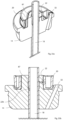
- FIG. 8 Another solution using a rotary plug is shown schematically.
- the rotary plug 46 can be used both as a sealing device and as a throttling device for throttling the volume flow of drinking liquid guided through the transport channel 18 as well as the volume flow of flavored air guided through the air channel 22.
- the Fig. 8 The rotary plug 46 shown is rotatably arranged in the head part of the drinking device and can be moved by the user in the direction of rotation H by operating the handwheel 50.
- Part of the rotary plug 46 is a shaft 52 which is rotatably guided in the housing and in which through openings 48a and 48b are located, which are arranged in the direction shown in Fig.
- the ratio of drinking liquid to flavored air can be varied.
- the openings 48b in the rotary plug and the x-shaped channels for transporting drinking liquid each have the same flow cross-section, while the x-shaped channels for transporting flavored air have different flow cross-sections.
- the opening 48a and the adjoining channel have a larger flow cross-section than the opening 48c and the adjoining channel.
- a user can, on the one hand, close the transport channel 18 and the air channel 22, and, on the other hand, set different flow cross-sections for the air channel 22 while the transport channel 18 is open for the drinking liquid, thus throttling the amount of flavored air.
- the advantage of the rotary plug is that the flow rate can be continuously adjusted and the operation of the locking device is intuitive for each user.
- a sports valve can be provided in which, similar to the embodiment according to Fig. 7 , the mouthpiece is moved in an axial direction between the closed and the open position.
- the actuation of the mouthpiece can be effected in addition to the transport channel 18 for drinking liquid and the air channel 22 for the transport of flavored Air, the air channel 32 can also be opened and closed simultaneously for pressure equalization.
- the mouthpiece is pulled out when the drinking device is to be put into the drinking state and pushed back towards the reservoir when the drinking device is to be sealed.
- there is no need to tip the drinking device when drinking since the drinking liquid and the flavored air are sucked in by the user.
- FIG. 9 The use of an integrated valve is in the Figs. 9 and 10 shown.
- the integrated valve is shown with separate air duct 22 for transporting flavored air and transport duct 18 for drinking liquid, while in Fig. 10 the transport channels 18 and 20 are connected in series, as shown schematically in the Fig. 1 was presented.
- the mouthpiece 16 of the drinking device can be pulled out in the direction of arrow J relative to the head part 14 and pushed in again.
- the transport channel 18 and the air channel 22 are open, so that drinking can be done from the drinking device.
- the air channel 32 is also opened for pressure equalization. If the mouthpiece 16 is now moved towards the head part 14 until the mouthpiece 16 lies firmly against the head part 14, the opening of the air channel 32 is tightly closed by the projection 54 on the mouthpiece 16.
- the flow connection from the head part to the mouthpiece is interrupted at the point where the air channel 22 enters the mouthpiece 16, so that the air channel 22 is closed. Furthermore, the movement in the direction of arrow K also closes the transport channel 18 for drinking liquid, so that with the help of the Fig. 9
- the integrated valve shown in the figure allows the transport channel 18 for drinking liquid, the air channel 22 for transporting flavored air and the air channel 32 for pressure equalization to be opened and closed simultaneously.
- Figs. 9 and 10 The shape of the mouthpiece shown in the area of the mouth end is only shown schematically and can of course have any shape that is ergonomic for the user.
- the mouthpiece 16 can be locked in the closed position by means of form-locking elements in the form of, for example, locking nipples 15a, 17a and corresponding recesses 15b and 17b, which are arranged in Fig. 10 are shown.
- the design according to Fig. 10 differs from that according to Fig. 9 only in that the air channel 22 for transporting flavored air in the mouthpiece 16 is not led to the mouth end 28, but opens into the transport channel 18 for drinking liquid in the area of the mouthpiece. Otherwise, however, the embodiment differs according to Fig. 10 not from the one after Fig. 9 , so that with regard to the operating principle of the sealing device, the designs according to Fig. 9 can be referred to.
- the embodiment according to Fig. 11a and 11b integrate the sealing device into the aroma container 20.
- the aroma container is pressed with the help of a finger in the direction of arrow L against the pressure force of a spring 56 in order to move the continuation 18b of the transport channel 18 for drinking liquid provided in the aroma container 20 into the Fig. 11b shown aligned connection with the sections 18a and 18c of the transport channel for drinking liquid.
- the liquid connection through the transport channel 18 only exists as long as a user actually presses on the aroma container 20 from the outside with his finger.
- Fig. 11a and 11b The aroma container can be rotated using the translational movement L shown, so that it can be rotated in a manner comparable to that shown in the Fig. 8
- the solution shown can be rotated between a locked position and at least one drinking position using a rotating plug.
- a different opening of the aroma container with a different cross-sectional size could be fluidly connected to the air channel 22 via different angles of rotation. This would allow the amount of flavored air and thus the flavor intensity to be controlled.
- Possible positions include "off,”"medium,” and “strong,” although in this example, an aroma container with two holes of different sizes would be necessary.
- the air channel 22 would be closed, making it possible to drink the liquid without air supply and without added flavor.
- a further advantage of this solution is that the aroma container also functions as the seal, thus requiring fewer components.
- a shut-off device can also be designed with a squeezing device.
- a section of the channel to be sealed for example the transport channel for drinking liquid, must be provided with a flexible hose which is squeezed together, for example, by a wheel arranged in a groove for rotational movement, thereby throttling or interrupting the flow connection.
- This technical solution meets hygienic requirements because there is no direct contact between the shut-off wheel and the substance conveyed in the transport channel. Therefore, this solution is also used, for example, in the medical field to adjust the transport volume for infusion liquids. If the actuating wheel is largely recessed in the head section of the drinking device, a low construction can be achieved with this technical solution.
- the drinking device can be designed in such a way that, for example, in the base of the drinking device there is a further receiving geometry for at least one additional aroma container, which can be exchanged for the existing aroma container as soon as the aroma container in use is exhausted or the consumer wishes to change the flavor.
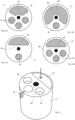
- Fig. 12a, 12b, 12c and 12d Embodiments are shown which schematically show a top view of the storage container 12, which is rotatably connected to a Fig. 12a to 12d The top view shows that each of the storage containers 12 has a filling opening 60 for drinking liquid.
- a single aroma container 20 is provided, while in the embodiments according to Fig. 12a and 12d
- Three aroma containers 20 are used in each case, although a different number of aroma containers is also possible.
- the corresponding receptacles 66 for the aroma containers 20 are in Fig. 13 As also shown in Fig. 13 As can be seen, the aroma containers 20 can be provided with a marking tab 62, which enables the aroma containers 20 to be removed after they have been inserted flush into the corresponding receptacle 66 in the storage container 12. In addition, the marking tabs 62 can be arranged such that they extend outside the storage container 12 and can thus provide the user with information about the aroma direction used.
- the individual flavor directions can be selected by adjusting the head part (not shown) relative to the body of the storage container 12.
- the head part is provided with corresponding markings or a locking mechanism (not shown), with the aid of which a user can establish the flow connection of the air channel 22 from one of the several flavor containers to the mouthpiece of the drinking device.
- the flavor direction can be changed even while drinking.
- pure drinking liquid can also be consumed.
- a mixing device 64 is arranged between the storage container 12 and the head part 14 with mouthpiece 16, which in the embodiment according to Fig. 14a three different receptacles for aroma containers 20, each of which is designed as an intermediate plate Mixing device 64 is used.
- a mixed aroma can be produced from various aroma substances, which is sucked off via the mixing ring 68 and fed to the mouthpiece via the adjoining air duct 22 in the head part 14.
- the Fig. 14a and 14b The technical solution presented offers the advantage that a user can create his own flavor combinations.
- FIG. 15 An alternative design is shown in which the aroma container 20 is divided into individual segments 20a, 20b, and 20c and is closed at the top by means of a lid 70. A user can freely combine the individual aromas that are inserted into the individual segments 20a, 20b, and 20c and from which a mixture is produced.
- this term also includes individual flavors that contain the same flavor but have a different flavor intensity.
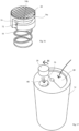
- the embodiment according to Fig. 16 outlines a possible fastening option for an aroma container 20, which is provided with a spring 56 on the lower side.
- the peripheral wall of the essentially circular-cylindrical aroma container 20 has, in addition to the fragrance hole 72 shown here, a guide 74, which is a groove with two sections arranged at an angle to one another.
- the first section 74a runs parallel to the rotation axis of the circular-cylindrical aroma container, whereas the second section 74b adjoins the first section 74a and extends in the circumferential direction to an end surface 74c.
- a possible associated storage container 12 is shown in Fig. 17 and shows similarities to the one in Fig.
- FIG. 12c shown geometry with a filling opening 60 formed essentially in the form of a semicircular segment and a receptacle 66 for the Fig. 16 shown aroma container, wherein on the peripheral wall of the receiving space 66 there is a projection 76 which is arranged and designed to be moved within the guide 74 during insertion.
- the storage container according to Fig. 17 could also be designed in such a way that no bayonet connection between the receiving space 66 and the aroma container 20 is required, since by placing a Fig. 17 shown head part of the aroma container is fixed.
- the aroma container When inserting the aroma container, it is thus initially inserted in the correct angular position relative to the projection 76 in the axial direction L, whereby the projection 76 passes through the first section 74a of the guide 74 and then moves relative to the receiving space 66 by rotating in the direction of arrow M, so that the projection 76 extends in the second section 74b and up to the stop surface 74c within the guide 74. As soon as the projection 76 abuts the stop surface 74c, the fragrance hole 72 is in flow connection with the air duct.
- FIG. 18a, 18b A separate mouthpiece 16 is shown, into which, as best shown in Fig. 19 As shown, an aroma container 20 can be inserted directly.
- the aroma container in this solution does not have to be replaceable, since instead of replacing the aroma container, the mouthpiece itself is replaced.
- the mouthpiece By replacing the mouthpiece together with the aroma container, hygiene is improved and the number of individual parts is reduced, as well as the use of the drinking device according to the invention is simplified.
- any solutions can be used, as long as the required seal exists between the mouthpiece and the head part of the drinking device.
- the schematic embodiment according to Fig. 20a and 20b shows a drinking device according to the invention, which is depicted as if the housing were transparent.
- the drinking device 10 again consists of a storage container 12 and a head part 14.
- a rotatable connection 58 which in the present example is depicted as a threaded bolt with a lock nut
- the head part 14 can be rotated relative to the storage container in the direction of arrow P.
- the aroma container 20 is inserted in the head part, and the air channel 22 for transporting aromatized air opens into the transport channel 18b for drinking liquid.
- the air channel 22 could be routed in the same way parallel to the transport channel 18b to the mouth end 28.
- the sections 18a and 18b of the transport channel for drinking liquid, but also the air channel 32 located in the head part are brought into flow connection with the air channel section 32b, so that in the Fig. 20b shown configuration, the drinking device is in an operational state. Since the parting plane 78 between the storage container 12 and the head part 14 does not run perpendicular to the cylindrical outer wall of the storage container 12, but is arranged at an angle to it, the Fig. 20b compared to Fig. 20a As shown, the position of the head part 14 between the sealed storage position and the drinking position. In this way, the user can not only be signaled whether the drinking device is in the drinking position, but also the most ergonomic position for drinking can be established.
- an aroma container 20 which is designed as an aroma ring, which is placed on the head part 14 in the immediate vicinity of the mouthpiece 28.
- the air channel 22 opens into the mouth shortly before the mouth end.
- Transport channel 18 for drinking liquid and the air channel 22 for transporting flavored air are to be led parallel to the mouth end 28.
- the ring-shaped aroma container 20 is divided into various segments 20a, 20b, 20c, and 20d, which can contain different aroma strengths or aroma directions.
- the marking 78 on the head portion 14 of the container indicates to the user which aroma chamber is in use. If the marking 78 is not aligned with the respective marking 80 on the individual chambers, then, in the embodiment according to Figs. 21 and 22 However, the connection between the aroma container and the transport channel 18 can also be blocked, so that a user cannot consume flavored drinking liquid via the system according to the invention.
- the aroma container could simply be inserted frictionally into a corresponding recess in the head part 14, thus allowing particularly simple and convenient handling for the user.
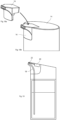
- the embodiment shown is a drinking device 10 which is an open-topped drinking cup.
- the aroma container 20 is shown in this embodiment as a ring which surrounds the outer periphery of the storage container 12 and can either, as in Fig. 23c shown, is connected to the transport channel 18 for drinking liquid via a short air channel 22 for transporting flavored air, or, as in Fig. 23c not shown, has an air channel that runs parallel to the transport channel for drinking liquid and up to the mouth end 28.
- the drinking cup as shown in Fig. 23b shown, the drinking liquid from the mouth end 28 (see Fig. 23a ) is sucked in, whereby, as in Fig. 1 As shown, the drinking liquid mixed with bubbles of flavored air is sucked in.
- a parallel routing of the transport channel 18 for drinking liquid and the air channel 22 for transporting flavored air is conceivable.
- the open drinking vessel shown could be a shot glass, which functions according to the same principle as the open drinking vessel and can also be used, for example, for spirits that are to be given additional flavor aromas.
- FIG. 24a and 24b A further embodiment of the invention is shown.
- the special feature of this embodiment is that the head part 14 can be screwed onto any bottle serving as a storage container 12.
- An aroma container is permanently installed in the head part 14, which transports the aromatized air via an air duct 22 (not shown) either parallel to the transport channel 18 for drinking liquid to the mouth end 28 or, according to the schematic representation in Fig. 1 opens into the transport channel 18 shortly before the mouth end 28.
- Fig. 24a and 24b A conventional bottle containing pure drinking liquid can be used, which can be reconfigured as desired by replacing the head portion 14 with the connected intake hose 80.
- This embodiment is particularly advantageous in regions where tap water is undrinkable due to inadequate quality, allowing consumers to purchase pure water as a drinking liquid, which can be modified to any desired flavor via the bottle attachment.
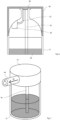
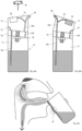
- the drinking device 10 consists of the storage container 12 designed as an open glass, as well as a drinking straw 82 to be arranged in the storage container, which combines the components and functionality of the intake hose 80, the transport channel 18 for drinking liquid, and, due to the aroma container 20 arranged in a ring around the drinking straw, also the air channel 22 for transporting aromatized air.
- the drinking straw 82 can be combined with any storage container 12, wherein the aroma container 20 is preferably not interchangeable but firmly connected to the drinking straw.
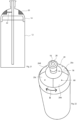
- FIG. 26a and 26b an embodiment is shown in which the illustrated head part 12 of the drinking device 10 (not shown) can be turned upside down during drinking, as consumers are familiar with, for example, drinking devices using a sports valve.
- the special feature of the embodiment according to Fig. 26a and 26b is that neither a suction tube 80 nor a drinking straw 82 is required. Without these elements, the drinking system according to the invention is easier to handle hygienically. Furthermore, this embodiment reduces the number of individual components, thereby simplifying production and shortening the assembly of the system. Furthermore, the consumer is accustomed to tilting his drinking bottle from conventional systems.
- Fig. 26a and 26b In contrast to the previously described embodiments, no liquid is accidentally spilled from the reservoir 12 during normal use.
- Fig. 26a and 26b The illustrated head part 14 can be connected to a storage vessel 12 via the illustrated thread 84 or another fastening option, whereby care must be taken to ensure that the connection prevents liquid leakage.
- a check valve 85 For pressure equalization between the inner and outer areas of the Drinking device 10 can be fitted with a check valve 85, as shown for example in Fig. 4a and 4b is shown.
- the aroma container is shown as a wide ring 83, the functional principle of which corresponds to the aroma container 20.
- the aroma reservoir is fluidically connected via the air channel 22.
- a movable mouthpiece (not shown here) must be pushed into the opening 86.
- This mouthpiece corresponds to a conventional mouthpiece of sports drinking bottles and must be made of a substantially flexible material. By sliding in the direction K, the mouthpiece (not shown) opens and closes the drinking device 10.
- FIG. 27a and Fig. 27b A preferred embodiment of the drinking device according to the invention is shown with a modification of the liquid channel 18 at the mouthpiece 16 in the head part 14 of the drinking device. It enables Fig. 27a shown taper 19 or the one in Fig. 27b
- the widening 23 of the channel at the mouthpiece 16 shown in FIG. 1 changes the pressure conditions in the liquid-air mixture. This changes the shape and size of the air bubbles, resulting in a more pleasant drinking experience.
- FIG. 28a and Fig. 28b A further preferred embodiment of the improvement of the drinking device 10 is shown in the Fig. 28a and Fig. 28b
- the preferred embodiment of the improvement according to the invention provides that the liquid channel 18 in the reservoir 12 of the drinking device 10 is tapered ( Fig. 28a - paragraph 21) or extended ( Fig. 28b - Number 25).
- the required suction pressure is essentially determined by the hydrostatic gravitational pressure of the liquid and the friction loss of the fluid on the wall of the liquid channel 18.
- the hydrostatic gravitational pressure is invariably directly proportional to the fill level in the storage container 12 and noticeably influences the suction pressure required by the drinker.
- this negative change can be partially or completely compensated for and thus the drinking experience can be improved.
- the pressure differences can be reduced by using a substantially wide but flat storage container (not shown here).
- FIG. 29 Another, in Fig. 29
- the preferred embodiment of the drinking device 10 shown in FIG. 1 provides that the air channel 22 in the head part 14 is tapered only at one point 27 and the air channel otherwise has a wider cross-section. This has the advantage that, despite the required small cross-section, in particular diameter, of the air channel 14, it is easier to produce and clean.
- liquid which flows from the liquid channel 18 into the air channel 22 can easily flow back into the liquid channel 18, resulting in hygienic advantages.
- FIG. 30a and Fig. 30b shown schematically.
- the head part 14 can be divided essentially axially symmetrically into two parts 14a and 14b. Both parts 14a, 14b contain on the inside a part of the air channel 22 and the liquid channel 18, which, when the two halves 14a, 14b are joined together in the direction of arrow C, form-fit the channels required for the drinking device.
- a fastening device 29, which in the Fig. 30a and Fig. 30b preferred embodiment is shown as a ring, can be reversibly held together by a displacement in the direction of arrow D on the two parts 14a and 14b.
- the separable head part 14 is shown in the drinking position.
- the recess 66 for the aroma reservoir 20 (not shown) is also cylindrical.
- a seal can be achieved by manufacturing the head part 14 from a substantially flexible material.
- a further preferred embodiment of the divisible head part 14 is shown in Fig. 31 shown.
- the recess 66 for the aroma reservoir 20 is also possible in the head section. Integration into the interior of the head section offers the advantage that the aroma reservoir 20 is not visible from the outside when the head section is closed. The aroma reservoir therefore needs to be designed less complexly, among other things, and evaporation of the aroma substance from the aroma reservoir during storage is slowed down.
- the aroma reservoir is inserted by joining the two parts 14a and 14b along the direction of arrow E. The two parts of the head section 14 are held together by a mechanism not shown here.
- FIG. 32a A further embodiment for optimizing a drinking device according to the invention is shown by way of example in the Fig. 32a, 32b and 32c
- Fig. 32a A preferred embodiment is shown in Fig. 32a the head part 14 of a drinking device is shown, which contains a liquid channel 18 and an air channel 22.
- Fig. 32a A fluid channel with a uniform shape over its entire length is shown.
- a preferred embodiment of a head part 14 of a drinking device in which the liquid channel 18 has a smaller diameter at the connection point of the liquid channel 18 with the air channel 22 than at the other points.
- the speed of the liquid increases in proportion to the cross-sections when flowing through the constricted part, since the amount of liquid does not change.
- the pressure in the air channel 22, which is attached at the narrowest point decreases. This creates a pressure difference that increases the absorption of the flavored air into the liquid in the drinking device.
- This effect known as the Venturi effect, significantly improves the drinking device.
- a further preferred embodiment is in Fig. 32c shown as an example and provides that a liquid channel 18 and an air channel 22 are arranged in the head part 14 of the drinking device, wherein at the connection point of the two channels, at least one of the two channels is wider than the cross-section of the other regions of the respective channels. This also enables a modified drinking experience for the user of the drinking device.
- FIG. 33a and 33b A further preferred embodiment of the head part 14 is shown in Fig. 33a and 33b shown as an example and provides that the air channel 22 is interrupted by a chamber 87 designed essentially as a recess on the outer wall of the liquid channel 18.
- the interruption of the air channel by a chamber 87 is designed such that a recess is provided in the head part 14 of the drinking device at the contact point between the removable riser 18 for the drinking liquid (liquid channel) and the air channel 22.
- the air channel 22 opens from the aroma container 20 into the chamber 87 at an upper position.
- the air channel is continued as channel 22b through the transport channel 18 at a lower position of the chamber 87.
- the chamber designed in this way prevents the drinking liquid from backflowing into the aroma reservoir 20.
- the opposite position of the continuation of the air channel 22 ensures the best possible use of the chamber 87.
- the different height positions of the inlet and outlet openings of the air duct 22 in and out of the chamber 87 enable, among other things, the drainage of drinking liquid back into the drinking liquid transport channel 18.
- the arrangement of the chamber 87 at the contact point between the head part 14, which can be made of a substantially elastic material, for example, and the drinking liquid transport channel 18 facilitates cleaning after disassembly of the components.
- Fig. 33a and Fig. 33b the air supply line 32 through the head part 14 into the storage container 12 for drinking liquid (not shown).
- Fig. 33b shows the embodiment of the head part 14 of the drinking device according to Fig. 33a in section, which illustrates the positions of the chamber 87 and the entry point of the air duct 22 as well as the exit point from the chamber 87 into the continuation of the air duct 22b.
Landscapes
- Mechanical Engineering (AREA)
- Engineering & Computer Science (AREA)
- Closures For Containers (AREA)
- Devices For Dispensing Beverages (AREA)
- Apparatus For Making Beverages (AREA)
- Eye Examination Apparatus (AREA)
- Confectionery (AREA)
- Details Of Rigid Or Semi-Rigid Containers (AREA)
- Formation And Processing Of Food Products (AREA)
- Table Devices Or Equipment (AREA)
- Disinfection, Sterilisation Or Deodorisation Of Air (AREA)
- Packging For Living Organisms, Food Or Medicinal Products That Are Sensitive To Environmental Conditiond (AREA)
- Package Specialized In Special Use (AREA)
Applications Claiming Priority (6)
| Application Number | Priority Date | Filing Date | Title |
|---|---|---|---|
| DE102017212472 | 2017-07-20 | ||
| DE102017009718 | 2017-10-18 | ||
| DE102018003669.4A DE102018003669A1 (de) | 2017-07-20 | 2018-05-05 | Trinkvorrichtung |
| PCT/EP2018/069108 WO2019016096A1 (fr) | 2017-07-20 | 2018-07-13 | Dispositif a boire |
| EP18743724.9A EP3655341B1 (fr) | 2017-07-20 | 2018-07-13 | Dispositif a boire |
| EP23189443.7A EP4249389B1 (fr) | 2017-07-20 | 2018-07-13 | Dispositif a boire |
Related Parent Applications (3)
| Application Number | Title | Priority Date | Filing Date |
|---|---|---|---|
| EP23189443.7A Division-Into EP4249389B1 (fr) | 2017-07-20 | 2018-07-13 | Dispositif a boire |
| EP23189443.7A Division EP4249389B1 (fr) | 2017-07-20 | 2018-07-13 | Dispositif a boire |
| EP18743724.9A Division EP3655341B1 (fr) | 2017-07-20 | 2018-07-13 | Dispositif a boire |
Publications (2)
| Publication Number | Publication Date |
|---|---|
| EP4544965A2 true EP4544965A2 (fr) | 2025-04-30 |
| EP4544965A3 EP4544965A3 (fr) | 2025-12-03 |
Family
ID=64951424
Family Applications (4)
| Application Number | Title | Priority Date | Filing Date |
|---|---|---|---|
| EP25163819.3A Pending EP4544965A3 (fr) | 2017-07-20 | 2018-07-13 | Dispositif pour boire |
| EP23189443.7A Active EP4249389B1 (fr) | 2017-07-20 | 2018-07-13 | Dispositif a boire |
| EP18743724.9A Active EP3655341B1 (fr) | 2017-07-20 | 2018-07-13 | Dispositif a boire |
| EP25199665.8A Pending EP4685074A1 (fr) | 2017-07-20 | 2018-07-13 | Dispositif pour boire |
Family Applications After (3)
| Application Number | Title | Priority Date | Filing Date |
|---|---|---|---|
| EP23189443.7A Active EP4249389B1 (fr) | 2017-07-20 | 2018-07-13 | Dispositif a boire |
| EP18743724.9A Active EP3655341B1 (fr) | 2017-07-20 | 2018-07-13 | Dispositif a boire |
| EP25199665.8A Pending EP4685074A1 (fr) | 2017-07-20 | 2018-07-13 | Dispositif pour boire |
Country Status (12)
| Country | Link |
|---|---|
| US (3) | US11564516B2 (fr) |
| EP (4) | EP4544965A3 (fr) |
| JP (4) | JP6990838B2 (fr) |
| CN (2) | CN110914169B (fr) |
| AU (3) | AU2018302386B2 (fr) |
| CA (2) | CA3070017C (fr) |
| DE (1) | DE102018003669A1 (fr) |
| ES (2) | ES2957290T3 (fr) |
| MX (1) | MX2023004449A (fr) |
| PL (2) | PL3655341T3 (fr) |
| SG (1) | SG11202000475VA (fr) |
| WO (1) | WO2019016096A1 (fr) |
Families Citing this family (60)
| Publication number | Priority date | Publication date | Assignee | Title |
|---|---|---|---|---|
| DE102018003669A1 (de) | 2017-07-20 | 2019-01-24 | Ten-Ace Gmbh | Trinkvorrichtung |
| DE102018222299A1 (de) * | 2018-12-19 | 2020-06-25 | Ten-Ace Gmbh | Trinkvorrichtung |
| EP3693289B1 (fr) * | 2019-02-06 | 2021-01-06 | Adivex GmbH | Pièce rapportée pour bouteille |
| DE102019113672B4 (de) | 2019-05-22 | 2022-02-03 | Cupssy Gmbh | Mehrzweckbehälter zum Bereitstellen von Tüchern mit einer Lufterfrischungsfunktion |
| CN113277215B (zh) * | 2020-02-20 | 2023-10-27 | 企划王有限公司 | 通气装置、盖体以及包括该盖体的容器 |
| DE202020102807U1 (de) | 2020-05-18 | 2021-08-30 | Ten-Ace Gmbh | Aromabehälter sowie Trinkvorrichtung mit einem Aromabehälter |
| AU2020448180A1 (en) * | 2020-05-18 | 2022-12-15 | air up group GmbH | Aroma container and drinking device having an aroma container |
| EP3944792A1 (fr) * | 2020-07-30 | 2022-02-02 | air up group GmbH | Dispositif à boire et récipient à boire |
| JP7580106B2 (ja) * | 2020-08-18 | 2024-11-11 | 株式会社Tacos | 飲料用容器および香料カートリッジ |
| KR102610987B1 (ko) * | 2020-09-11 | 2023-12-08 | 한국전자통신연구원 | 컵에 부착된 발향 장치 및 이를 이용한 발향 방법 |
| WO2022111808A1 (fr) * | 2020-11-26 | 2022-06-02 | air up group GmbH | Dispositif permettant de boire |
| GB2598806B (en) * | 2020-12-08 | 2023-02-08 | Avec Coffee Ltd | Device for use with a beverage container |
| FR3119743B3 (fr) * | 2021-02-16 | 2023-03-10 | Nestle Sa | Paille en papier ayant des proprietes organoleptiques ameliorees |
| FR3119841B3 (fr) * | 2021-02-16 | 2023-03-03 | Nestle Sa | Couvercle de gobelet a boisson pour proprietes organoleptiques ameliorees |
| DE102021202093A1 (de) | 2021-03-04 | 2022-09-08 | air up group GmbH | Aromabehälter sowie Trinkvorrichtung mit einem Aromabehälter |
| DE102021105519A1 (de) | 2021-03-08 | 2022-09-08 | August Töpfer & Co. (GmbH & Co.) KG | Aromaspeicher für die Speicherung von Duftstoffen, Verfahren zu seiner Herstellung sowie Trinksystem mit einem solchen Aromaspeicher |
| CN112793927A (zh) * | 2021-03-22 | 2021-05-14 | 上海捷力健康科技发展有限公司 | 饮料用容器及香料盒 |
| DE202021101790U1 (de) | 2021-04-01 | 2022-07-19 | August Töpfer & Co. (GmbH & Co.) KG | Aromaspeicher für die Speicherung von Duftstoffen sowie Trinksystem mit einem solchen Aromaspeicher |
| CN113180442A (zh) * | 2021-05-20 | 2021-07-30 | 龙景辉 | 一种外加香的饮水器皿 |
| WO2023283733A1 (fr) * | 2021-07-13 | 2023-01-19 | Yetter Dustin Martin | Dispositif de distribution de parfum |
| DE102021129285A1 (de) | 2021-11-10 | 2023-05-11 | August Töpfer & Co. (GmbH & Co.) KG | Trinksystem |
| KR20240112890A (ko) | 2021-11-30 | 2024-07-19 | 에어 업 그룹 게엠베하 | 아로마 물질의 비후적 수용을 위한 음용 장치용 부착물 및 음용 장치 |
| CN116268907B (zh) * | 2021-12-13 | 2025-12-02 | 安威技术香港有限公司 | 一种吸管杯及其杯盖 |
| CN116491797A (zh) * | 2022-01-27 | 2023-07-28 | 安威技术香港有限公司 | 一种吸管杯及其杯盖 |
| DE202022000335U1 (de) | 2022-02-09 | 2022-05-27 | Andràs Biczó | Universeller Mehrwegdeckel mit Trinköffnung für Trinkgefäße zur retronasalen Aufnahme von Aromastoffen |
| WO2023152091A1 (fr) * | 2022-02-11 | 2023-08-17 | Givaudan Sa | Procédé durable de compoundage d'arômes et de parfums |
| DE102022105794B3 (de) | 2022-03-11 | 2022-12-29 | August Töpfer & Co. (GmbH & Co.) KG | Trinksystem |
| CN116491798B (zh) * | 2022-07-05 | 2026-04-24 | 安威技术香港有限公司 | 一种吸管杯及其杯盖 |
| EP4321061B1 (fr) | 2022-08-08 | 2026-02-11 | air up group GmbH | Embout buccal pour un système de boisson au goût basé sur les odeurs |
| CN217852291U (zh) * | 2022-08-27 | 2022-11-22 | 扬州特尔美化妆品有限公司 | 一种香氛杯的新型杯盖结构 |
| DE102022131804B4 (de) * | 2022-11-30 | 2025-11-06 | August Töpfer & Co. (GmbH & Co.) KG | Trinkhalmvorrichtung und Trinksystem |
| DE102023103059A1 (de) | 2023-02-08 | 2024-08-08 | August Töpfer & Co. (GmbH & Co.) KG | Trinkhalmvorrichtung und Trinksystem mit einer solchen |
| CN219249780U (zh) * | 2023-04-12 | 2023-06-27 | 广州热带雨林实业有限公司 | 一种鼻后摄入香味物质的饮用装置 |
| DE202023102688U1 (de) | 2023-05-17 | 2023-06-05 | air up group GmbH | Trinkvorrichtung zur retronasalen Aufnahme einer Aromasubstanz |
| DE102023204631A1 (de) * | 2023-05-17 | 2024-11-21 | air up group GmbH | Trinkvorrichtung zur retronasalen Aufnahme einer Aromasubstanz |
| WO2024246506A1 (fr) * | 2023-05-28 | 2024-12-05 | Brook Chrispin Samantha | Dispositif de distribution de liquide |
| DE102023118018B4 (de) | 2023-07-07 | 2026-02-05 | magic water GmbH | Trinkflasche |
| DE102023120791A1 (de) | 2023-08-04 | 2025-02-06 | magic water GmbH | Trinkflasche |
| USD1080299S1 (en) * | 2023-08-16 | 2025-06-24 | Taizhou Kunhai Plastic Industry Co., Ltd. | Accessory for drinking cup |
| DE202023001786U1 (de) | 2023-08-24 | 2023-12-11 | Koun Alasfir | Doppelstrohhalm mit versetzten Öffnungen im Mundstück |
| DE102023130842A1 (de) * | 2023-11-07 | 2025-05-08 | magic water GmbH | Trinkvorrichtung |
| EP4606272A1 (fr) | 2024-02-22 | 2025-08-27 | air up group GmbH | Structure de fermeture, système d'un récipient d'arôme remplaçable et structure de fermeture de ce type et dispositif de boisson associé |
| EP4616770A1 (fr) | 2024-03-14 | 2025-09-17 | air up group GmbH | Structure de fermeture pour un récipient rechargeable et dispositif de boisson |
| EP4627974A1 (fr) | 2024-04-04 | 2025-10-08 | air up group GmbH | Adaptateur pour paille et dispositif de boisson |
| EP4627972A1 (fr) | 2024-04-04 | 2025-10-08 | air up group GmbH | Accessoire pour un dispositif de boisson et dispositif de boisson |
| DE102024109757A1 (de) * | 2024-04-08 | 2025-10-09 | magic water GmbH | Trinkvorrichtung |
| DE102024109756A1 (de) * | 2024-04-08 | 2025-10-09 | magic water GmbH | Trinksystem und Trinkflüssigkeit |
| WO2025214914A1 (fr) | 2024-04-08 | 2025-10-16 | magic water GmbH | Dispositif de consommation de boisson |
| WO2025237505A1 (fr) | 2024-05-13 | 2025-11-20 | Edin Ramic | Accessoire pour boire destiné à être relié à un récipient de boisson, dispositif pour boire comprenant l'accessoire pour boire et unité d'arôme pour un accessoire pour boire |
| DE102024115322A1 (de) | 2024-06-03 | 2025-12-04 | magic water GmbH | Trinkvorrichtung zum retronasalen Trinken |
| FR3164189A1 (fr) * | 2024-07-05 | 2026-01-09 | Christine HEDARCHET | Diffuseur d’arôme pour bouteille |
| FR3164195A1 (fr) * | 2024-07-05 | 2026-01-09 | Christine HEDARCHET | Diffuseur d’arôme pour bouteille d’eau jetable |
| FR3164187A1 (fr) * | 2024-07-05 | 2026-01-09 | Christine HEDARCHET | Diffuseur d’arôme pour bouteille d’eau jetable |
| FR3164188A1 (fr) * | 2024-07-05 | 2026-01-09 | Christine HEDARCHET | Diffuseur d’arôme pour bouteille d’eau jetable |
| WO2026008939A1 (fr) * | 2024-07-05 | 2026-01-08 | Christine Hedarchet | Diffuseur d'arome pour bouteille |
| GR20240100503A (el) * | 2024-07-18 | 2026-02-06 | Μηλοπουλου, Χριστινα Γεωργιου | Συσκευη για την αναρροφηση τροφων |
| EP4714308A1 (fr) | 2024-09-23 | 2026-03-25 | air up group GmbH | Structure de fermeture pour un dispositif de boisson et dispositif de boisson |
| EP4728876A1 (fr) * | 2024-10-16 | 2026-04-22 | air up group GmbH | Système de complément alimentaire et utilisation |
| DE102024130867A1 (de) * | 2024-10-23 | 2026-04-23 | magic water GmbH | Trinkflasche |
| US12466622B1 (en) * | 2025-05-26 | 2025-11-11 | Da Teng | Aromatic water cup |
Citations (6)
| Publication number | Priority date | Publication date | Assignee | Title |
|---|---|---|---|---|
| US5635229A (en) | 1995-03-20 | 1997-06-03 | Ray; Kenneth W. | Beverage container including an affixed scent disbursement means for enhancing perceived flavor of the beverage |
| US20040261807A1 (en) | 2003-06-23 | 2004-12-30 | Dube Michael Francis | Filtered cigarette incorporating a breakable capsule |
| US20080028353A1 (en) | 2006-07-18 | 2008-01-31 | Ning Lu | Method for treating parasitic resistance, capacitance, and inductance in the design flow of integrated circuit extraction, simulations, and analyses |
| US8662904B2 (en) | 2011-10-28 | 2014-03-04 | Aces Electronics Co., Ltd. | Electrical power connector having a housing with stepped stop portions, partition plates and hooks for engaging openings in the terminals |
| US8662339B2 (en) | 2009-12-30 | 2014-03-04 | Timothy R. Sprunger | Flavor enhancement apparatus and method |
| US20150030726A1 (en) | 2011-12-14 | 2015-01-29 | Erber Aktiengesellscaft | Additive for selenium-containing forage |
Family Cites Families (39)
| Publication number | Priority date | Publication date | Assignee | Title |
|---|---|---|---|---|
| BE530009A (fr) * | 1953-06-30 | |||
| US4083372A (en) * | 1976-05-24 | 1978-04-11 | Robert Boden | Cigarette-simulating inhaler |
| US4955503A (en) * | 1989-02-02 | 1990-09-11 | Propes Michael L | Partitioned drinking cup |
| US5433353A (en) * | 1991-11-21 | 1995-07-18 | Flinn; Christopher R. | Fluid storage and dispensing container having check valve |
| US5440976A (en) * | 1994-08-23 | 1995-08-15 | Fred Giuliano | Adjustable dispensing stirrer for soluble sweeteners |
| US5645161A (en) * | 1996-01-22 | 1997-07-08 | Orlandi Inc. | Fragrance packet sampler |
| GB2320017A (en) * | 1996-12-06 | 1998-06-10 | Christopher Nigel Staf Tribble | Vented container for easy pouring or drinking |
| US6045833A (en) * | 1997-02-07 | 2000-04-04 | Landau; Steven M. | Receptacle having aromatic properties and method of use |
| JPH11348981A (ja) * | 1998-06-09 | 1999-12-21 | Terumo Corp | 飲料用容器 |
| DE29915432U1 (de) * | 1999-09-02 | 1999-12-30 | Weber-Unger, Georg, Kufstein | Trinkgefäß |
| CN2389124Y (zh) | 1999-10-12 | 2000-07-26 | 刘志祥 | 带吸管的瓶嘴 |
| CN2461872Y (zh) | 2001-01-13 | 2001-11-28 | 姚远 | 带吸管的自动喷吸饮料瓶盖 |
| JP3486403B2 (ja) | 2001-06-08 | 2004-01-13 | ピジョン株式会社 | 乳幼児用飲料容器 |
| US7175614B2 (en) * | 2002-10-17 | 2007-02-13 | Baxter International Inc. | Peelable seal |
| DE60333048D1 (de) | 2002-11-30 | 2010-07-29 | Lee Jung Min | Behälter für Lebensmittel und Getränke |
| JP2004026304A (ja) | 2003-02-27 | 2004-01-29 | Seizo Morikawa | 飲料用の缶 |
| US20070062961A1 (en) * | 2005-09-16 | 2007-03-22 | Pleo Originals, Llc | Ergonomic wine glass |
| US20070075079A1 (en) | 2005-10-05 | 2007-04-05 | Harlan Stokes | Flavored container lid |
| WO2007052227A2 (fr) * | 2005-11-01 | 2007-05-10 | The Procter & Gamble Company | Recipient contenant des moyens parfumants |
| ITPD20050336A1 (it) * | 2005-11-22 | 2007-05-23 | Cappello Srl | Tappo per la chiusura di bottiglie, particolarmente per la chiusura di bottiglie di vino da invecchiamento |
| JP3125880U (ja) * | 2006-07-24 | 2006-10-05 | 株式会社 プラス化成 | 差圧弁付き保温保冷水筒 |
| EP1972213A1 (fr) * | 2007-03-21 | 2008-09-24 | Philip Morris Products S.A. | Filtre multi-composant fournissant une amélioration de la saveur |
| US20080290059A1 (en) | 2007-05-25 | 2008-11-27 | Zach Benbassat | Multi flavor beverage bottle |
| US20090266829A1 (en) * | 2008-04-24 | 2009-10-29 | Craig Bailey | Disposable foam enhancing espresso drink lid |
| FR2938243B1 (fr) * | 2008-11-12 | 2013-08-23 | Soc D Thermoformage Et D Injection Des Plastics | Dispositif pour la conservation et la liberation d'un produit contenu dans un reservoir comprenant une paroi rupturable |
| CN102595979B (zh) | 2009-11-02 | 2014-05-07 | Pi-设计公开股份公司 | 带有可关闭倾倒开口的沏茶器 |
| JP5495999B2 (ja) * | 2010-07-16 | 2014-05-21 | ピジョン株式会社 | 飲料容器 |
| CN201901325U (zh) * | 2010-11-26 | 2011-07-20 | 郑琨 | 一种洗浴液包装瓶 |
| CN102145777A (zh) * | 2011-04-29 | 2011-08-10 | 李联明 | 花茶熏香酒瓶 |
| US20130302477A1 (en) * | 2012-05-08 | 2013-11-14 | Dr Pepper/Seven Up, Inc. | Consumable items provided with scented packaging and using scent to reduce ingredients in consumable items |
| JP5662536B1 (ja) * | 2013-09-05 | 2015-01-28 | サーモス株式会社 | 飲料用容器 |
| US9289083B2 (en) * | 2013-10-15 | 2016-03-22 | Robert Lee | Food container with discard compartment |
| JP6566556B2 (ja) * | 2015-07-31 | 2019-08-28 | 株式会社リッチェル | 飲料容器 |
| CN105947383A (zh) * | 2016-06-29 | 2016-09-21 | 吴凰 | 一种香水瓶盖 |
| DE202016004961U1 (de) * | 2016-08-05 | 2016-09-14 | Tim Jäger | Trinkgefäß |
| CN106820859A (zh) * | 2017-03-16 | 2017-06-13 | 邬惠林 | 一种喝白水也能闻到果汁香味的水杯 |
| DE102018003669A1 (de) | 2017-07-20 | 2019-01-24 | Ten-Ace Gmbh | Trinkvorrichtung |
| DE202018000382U1 (de) | 2018-01-24 | 2018-05-09 | smaak UG (haftungsbeschränkt) | Vorrichtung zur Simulation von Geschmack durch retronasales Riechen von Aromen in Kombination mit dem Trinken von Flüssigkeiten aus allgemein gebräuchlichen Trinkgefäßen. |
| DE102018222299A1 (de) | 2018-12-19 | 2020-06-25 | Ten-Ace Gmbh | Trinkvorrichtung |
-
2018
- 2018-05-05 DE DE102018003669.4A patent/DE102018003669A1/de active Pending
- 2018-07-13 SG SG11202000475VA patent/SG11202000475VA/en unknown
- 2018-07-13 EP EP25163819.3A patent/EP4544965A3/fr active Pending
- 2018-07-13 WO PCT/EP2018/069108 patent/WO2019016096A1/fr not_active Ceased
- 2018-07-13 EP EP23189443.7A patent/EP4249389B1/fr active Active
- 2018-07-13 ES ES18743724T patent/ES2957290T3/es active Active
- 2018-07-13 CN CN201880047939.XA patent/CN110914169B/zh active Active
- 2018-07-13 US US16/631,432 patent/US11564516B2/en active Active
- 2018-07-13 PL PL18743724.9T patent/PL3655341T3/pl unknown
- 2018-07-13 CA CA3070017A patent/CA3070017C/fr active Active
- 2018-07-13 CA CA3207029A patent/CA3207029A1/fr active Pending
- 2018-07-13 JP JP2020524675A patent/JP6990838B2/ja active Active
- 2018-07-13 CN CN202111183536.8A patent/CN113978917B/zh active Active
- 2018-07-13 EP EP18743724.9A patent/EP3655341B1/fr active Active
- 2018-07-13 PL PL23189443.7T patent/PL4249389T3/pl unknown
- 2018-07-13 AU AU2018302386A patent/AU2018302386B2/en active Active
- 2018-07-13 EP EP25199665.8A patent/EP4685074A1/fr active Pending
- 2018-07-13 ES ES23189443T patent/ES3043084T3/es active Active
-
2020
- 2020-01-17 MX MX2023004449A patent/MX2023004449A/es unknown
-
2021
- 2021-11-10 JP JP2021183252A patent/JP7355799B2/ja active Active
-
2022
- 2022-12-02 US US18/074,226 patent/US11793336B2/en active Active
-
2023
- 2023-09-14 US US18/467,607 patent/US20240000249A1/en active Pending
- 2023-09-21 JP JP2023155513A patent/JP2023164692A/ja active Pending
- 2023-10-26 AU AU2023254979A patent/AU2023254979B2/en active Active
-
2025
- 2025-11-10 JP JP2025188942A patent/JP2026015420A/ja active Pending
-
2026
- 2026-02-17 AU AU2026201187A patent/AU2026201187A1/en active Pending
Patent Citations (6)
| Publication number | Priority date | Publication date | Assignee | Title |
|---|---|---|---|---|
| US5635229A (en) | 1995-03-20 | 1997-06-03 | Ray; Kenneth W. | Beverage container including an affixed scent disbursement means for enhancing perceived flavor of the beverage |
| US20040261807A1 (en) | 2003-06-23 | 2004-12-30 | Dube Michael Francis | Filtered cigarette incorporating a breakable capsule |
| US20080028353A1 (en) | 2006-07-18 | 2008-01-31 | Ning Lu | Method for treating parasitic resistance, capacitance, and inductance in the design flow of integrated circuit extraction, simulations, and analyses |
| US8662339B2 (en) | 2009-12-30 | 2014-03-04 | Timothy R. Sprunger | Flavor enhancement apparatus and method |
| US8662904B2 (en) | 2011-10-28 | 2014-03-04 | Aces Electronics Co., Ltd. | Electrical power connector having a housing with stepped stop portions, partition plates and hooks for engaging openings in the terminals |
| US20150030726A1 (en) | 2011-12-14 | 2015-01-29 | Erber Aktiengesellscaft | Additive for selenium-containing forage |
Also Published As
Similar Documents
| Publication | Publication Date | Title |
|---|---|---|
| EP4249389B1 (fr) | Dispositif a boire | |
| EP4242129B1 (fr) | Dispositif pour boire | |
| EP4251012B1 (fr) | Dispositif permettant de boire | |
| DE102022105794B3 (de) | Trinksystem | |
| HK40097457B (en) | Drinking device | |
| HK40097457A (en) | Drinking device | |
| HK40067413B (zh) | 饮用装置 | |
| HK40067413A (en) | Drinking device | |
| BR122022026004B1 (pt) | Dispositivo para ingestão de líquido | |
| BR112020000975B1 (pt) | Dispositivo para ingestão de líquido | |
| HK40023777A (en) | Drinking device | |
| HK40023777B (en) | Drinking device |
Legal Events
| Date | Code | Title | Description |
|---|---|---|---|
| PUAI | Public reference made under article 153(3) epc to a published international application that has entered the european phase |
Free format text: ORIGINAL CODE: 0009012 |
|
| STAA | Information on the status of an ep patent application or granted ep patent |
Free format text: STATUS: REQUEST FOR EXAMINATION WAS MADE |
|
| 17P | Request for examination filed |
Effective date: 20250314 |
|
| AC | Divisional application: reference to earlier application |
Ref document number: 3655341 Country of ref document: EP Kind code of ref document: P Ref document number: 4249389 Country of ref document: EP Kind code of ref document: P |
|
| AK | Designated contracting states |
Kind code of ref document: A2 Designated state(s): AL AT BE BG CH CY CZ DE DK EE ES FI FR GB GR HR HU IE IS IT LI LT LU LV MC MK MT NL NO PL PT RO RS SE SI SK SM TR |
|
| REG | Reference to a national code |
Ref country code: DE Ref legal event code: R079 Free format text: PREVIOUS MAIN CLASS: A47G0021180000 Ipc: B65D0047060000 |
|
| RIC1 | Information provided on ipc code assigned before grant |
Ipc: B65D 47/06 20060101AFI20250620BHEP Ipc: B65D 47/26 20060101ALI20250620BHEP Ipc: B65D 47/30 20060101ALI20250620BHEP Ipc: B65D 51/24 20060101ALI20250620BHEP Ipc: A47G 19/22 20060101ALI20250620BHEP Ipc: A47G 21/18 20060101ALI20250620BHEP |
|
| PUAL | Search report despatched |
Free format text: ORIGINAL CODE: 0009013 |
|
| AK | Designated contracting states |
Kind code of ref document: A3 Designated state(s): AL AT BE BG CH CY CZ DE DK EE ES FI FR GB GR HR HU IE IS IT LI LT LU LV MC MK MT NL NO PL PT RO RS SE SI SK SM TR |
|
| RIC1 | Information provided on ipc code assigned before grant |
Ipc: B65D 47/06 20060101AFI20251027BHEP Ipc: B65D 47/26 20060101ALI20251027BHEP Ipc: B65D 47/30 20060101ALI20251027BHEP Ipc: B65D 51/24 20060101ALI20251027BHEP Ipc: A47G 19/22 20060101ALI20251027BHEP Ipc: A47G 21/18 20060101ALI20251027BHEP Ipc: B65D 77/22 20060101ALI20251027BHEP |
|
| REG | Reference to a national code |
Ref country code: HK Ref legal event code: DE Ref document number: 40126078 Country of ref document: HK |
|
| STAA | Information on the status of an ep patent application or granted ep patent |
Free format text: STATUS: EXAMINATION IS IN PROGRESS |
|
| 17Q | First examination report despatched |
Effective date: 20260107 |