EP4544996A1 - Elektronische vorrichtung zur messung biometrischer informationen und betriebsverfahren dafür - Google Patents
Elektronische vorrichtung zur messung biometrischer informationen und betriebsverfahren dafür Download PDFInfo
- Publication number
- EP4544996A1 EP4544996A1 EP23857503.9A EP23857503A EP4544996A1 EP 4544996 A1 EP4544996 A1 EP 4544996A1 EP 23857503 A EP23857503 A EP 23857503A EP 4544996 A1 EP4544996 A1 EP 4544996A1
- Authority
- EP
- European Patent Office
- Prior art keywords
- electronic device
- biometric information
- biometric
- sensor
- acquiring
- Prior art date
- Legal status (The legal status is an assumption and is not a legal conclusion. Google has not performed a legal analysis and makes no representation as to the accuracy of the status listed.)
- Pending
Links
Images







Classifications
-
- A—HUMAN NECESSITIES
- A61—MEDICAL OR VETERINARY SCIENCE; HYGIENE
- A61B—DIAGNOSIS; SURGERY; IDENTIFICATION
- A61B5/00—Measuring for diagnostic purposes; Identification of persons
-
- A—HUMAN NECESSITIES
- A61—MEDICAL OR VETERINARY SCIENCE; HYGIENE
- A61B—DIAGNOSIS; SURGERY; IDENTIFICATION
- A61B5/00—Measuring for diagnostic purposes; Identification of persons
- A61B5/72—Signal processing specially adapted for physiological signals or for diagnostic purposes
- A61B5/7271—Specific aspects of physiological measurement analysis
- A61B5/7285—Specific aspects of physiological measurement analysis for synchronizing or triggering a physiological measurement or image acquisition with a physiological event or waveform, e.g. an ECG signal
-
- A—HUMAN NECESSITIES
- A61—MEDICAL OR VETERINARY SCIENCE; HYGIENE
- A61B—DIAGNOSIS; SURGERY; IDENTIFICATION
- A61B5/00—Measuring for diagnostic purposes; Identification of persons
- A61B5/0002—Remote monitoring of patients using telemetry, e.g. transmission of vital signals via a communication network
-
- A—HUMAN NECESSITIES
- A61—MEDICAL OR VETERINARY SCIENCE; HYGIENE
- A61B—DIAGNOSIS; SURGERY; IDENTIFICATION
- A61B5/00—Measuring for diagnostic purposes; Identification of persons
- A61B5/0059—Measuring for diagnostic purposes; Identification of persons using light, e.g. diagnosis by transillumination, diascopy, fluorescence
- A61B5/0077—Devices for viewing the surface of the body, e.g. camera, magnifying lens
-
- A—HUMAN NECESSITIES
- A61—MEDICAL OR VETERINARY SCIENCE; HYGIENE
- A61B—DIAGNOSIS; SURGERY; IDENTIFICATION
- A61B5/00—Measuring for diagnostic purposes; Identification of persons
- A61B5/02—Detecting, measuring or recording for evaluating the cardiovascular system, e.g. pulse, heart rate, blood pressure or blood flow
- A61B5/0205—Simultaneously evaluating both cardiovascular conditions and different types of body conditions, e.g. heart and respiratory condition
-
- A—HUMAN NECESSITIES
- A61—MEDICAL OR VETERINARY SCIENCE; HYGIENE
- A61B—DIAGNOSIS; SURGERY; IDENTIFICATION
- A61B5/00—Measuring for diagnostic purposes; Identification of persons
- A61B5/02—Detecting, measuring or recording for evaluating the cardiovascular system, e.g. pulse, heart rate, blood pressure or blood flow
- A61B5/024—Measuring pulse rate or heart rate
-
- A—HUMAN NECESSITIES
- A61—MEDICAL OR VETERINARY SCIENCE; HYGIENE
- A61B—DIAGNOSIS; SURGERY; IDENTIFICATION
- A61B5/00—Measuring for diagnostic purposes; Identification of persons
- A61B5/02—Detecting, measuring or recording for evaluating the cardiovascular system, e.g. pulse, heart rate, blood pressure or blood flow
- A61B5/024—Measuring pulse rate or heart rate
- A61B5/02416—Measuring pulse rate or heart rate using photoplethysmograph signals, e.g. generated by infrared radiation
-
- A—HUMAN NECESSITIES
- A61—MEDICAL OR VETERINARY SCIENCE; HYGIENE
- A61B—DIAGNOSIS; SURGERY; IDENTIFICATION
- A61B5/00—Measuring for diagnostic purposes; Identification of persons
- A61B5/145—Measuring characteristics of blood in vivo, e.g. gas concentration or pH-value ; Measuring characteristics of body fluids or tissues, e.g. interstitial fluid or cerebral tissue
- A61B5/1455—Measuring characteristics of blood in vivo, e.g. gas concentration or pH-value ; Measuring characteristics of body fluids or tissues, e.g. interstitial fluid or cerebral tissue using optical sensors, e.g. spectral photometrical oximeters
-
- A—HUMAN NECESSITIES
- A61—MEDICAL OR VETERINARY SCIENCE; HYGIENE
- A61B—DIAGNOSIS; SURGERY; IDENTIFICATION
- A61B5/00—Measuring for diagnostic purposes; Identification of persons
- A61B5/68—Arrangements of detecting, measuring or recording means, e.g. sensors, in relation to patient
- A61B5/6801—Arrangements of detecting, measuring or recording means, e.g. sensors, in relation to patient specially adapted to be attached to or worn on the body surface
- A61B5/6802—Sensor mounted on worn items
- A61B5/681—Wristwatch-type devices
-
- A—HUMAN NECESSITIES
- A61—MEDICAL OR VETERINARY SCIENCE; HYGIENE
- A61B—DIAGNOSIS; SURGERY; IDENTIFICATION
- A61B5/00—Measuring for diagnostic purposes; Identification of persons
- A61B5/68—Arrangements of detecting, measuring or recording means, e.g. sensors, in relation to patient
- A61B5/6801—Arrangements of detecting, measuring or recording means, e.g. sensors, in relation to patient specially adapted to be attached to or worn on the body surface
- A61B5/6843—Monitoring or controlling sensor contact pressure
-
- A—HUMAN NECESSITIES
- A61—MEDICAL OR VETERINARY SCIENCE; HYGIENE
- A61B—DIAGNOSIS; SURGERY; IDENTIFICATION
- A61B5/00—Measuring for diagnostic purposes; Identification of persons
- A61B5/68—Arrangements of detecting, measuring or recording means, e.g. sensors, in relation to patient
- A61B5/6887—Arrangements of detecting, measuring or recording means, e.g. sensors, in relation to patient mounted on external non-worn devices, e.g. non-medical devices
- A61B5/6898—Portable consumer electronic devices, e.g. music players, telephones, tablet computers
-
- A—HUMAN NECESSITIES
- A61—MEDICAL OR VETERINARY SCIENCE; HYGIENE
- A61B—DIAGNOSIS; SURGERY; IDENTIFICATION
- A61B5/00—Measuring for diagnostic purposes; Identification of persons
- A61B5/72—Signal processing specially adapted for physiological signals or for diagnostic purposes
- A61B5/7221—Determining signal validity, reliability or quality
Definitions
- Embodiments of the disclosure relate to an electronic device for measuring biometric information and an operation method thereof.
- an electronic device may acquire photoplethysmograph (PPG) signals via a PPG sensor.
- the electronic device can provide the user with biometric information on at least one of pulse, saturation of peripheral oxygen (SpO 2 ), or blood pressure measured using the PPG signals.
- PPG photoplethysmograph
- an electronic device may include a first sensor, a memory, and at least one processor.
- the memory may store at least one instruction that, when executed by the at least one processor, causes the electronic device to acquire a first biometric signal for measuring first biometric information of a user based on a first configuration value through the first sensor.
- the memory may store at least one instruction that, when executed by the at least one processor, causes the electronic device to acquire first data on the first biometric information measured based on the first biometric signal.
- the memory may store at least one instruction that, when executed by the at least one processor, causes the electronic device to determine whether re-measurement of the first biometric information is requested within a designated time from a time point of acquiring the first data when re-measurement of the first biometric information is requested.
- the memory may store at least one instruction that, when executed by the at least one processor, causes the electronic device to acquire a second biometric signal for measuring the first biometric information based on a second configuration value different from the first configuration value through the first sensor based on the determination that re-measurement of the first biometric information is requested within the designated time from the time point of acquiring the first data.
- an operation method of an electronic device may include acquiring a first biometric signal for measuring first biometric information of a user based on a first configuration value through a first sensor included in the electronic device.
- the operation method of the electronic device may include acquiring first data on the first biometric information measured based on the first biometric signal.
- the operation method of the electronic device may include determining whether re-measurement of the first biometric information is requested within a designated time from the time point of acquiring the first data when re-measurement of the first biometric information is requested.
- the operation method of the electronic device may include acquiring a second biometric signal for measuring the first biometric information based on a second configuration value different from the first configuration value through the first sensor based on the determination that re-measurement of the first biometric information is requested within the designated time from the time point of acquiring the first data.
- a non-transitory recording medium may store at least one instruction capable of executing an operation of acquiring a first biometric signal for measuring first biometric information of a user based on a first configuration value through a first sensor included in an electronic device.
- the non-transitory recording medium may store at least one instruction capable of executing an operation of acquiring first data on the first biometric information measured based on the first biometric signal.
- the non-transitory recording medium may store at least one instruction capable of executing an operation of determining whether re-measurement of the first biometric information is requested within a designated time from the time point of acquiring the first data when re-measurement of the first biometric information is requested.
- the non-transitory recording medium may store at least one instruction capable of executing an operation of acquiring a second biometric signal for measuring the first biometric information based on a second configuration value different from the first configuration value through the first sensor based on the determination that re-measurement of the first biometric information is requested within the designated time from the time point of acquiring the first data.
- FIG. 1 is a block diagram illustrating an electronic device 101 in a network environment 100 according to various embodiments.
- the electronic device 101 in the network environment 100 may communicate with an electronic device 102 via a first network 198 (e.g., a short-range wireless communication network), or at least one of an electronic device 104 or a server 108 via a second network 199 (e.g., a long-range wireless communication network).
- the electronic device 101 may communicate with the electronic device 104 via the server 108.
- the processor 120 may execute, for example, software (e.g., a program 140) to control at least one other component (e.g., a hardware or software component) of the electronic device 101 coupled with the processor 120, and may perform various data processing or computation. According to one embodiment, as at least part of the data processing or computation, the processor 120 may store a command or data received from another component (e.g., the sensor module 176 or the communication module 190) in volatile memory 132, process the command or the data stored in the volatile memory 132, and store resulting data in non-volatile memory 134.
- software e.g., a program 140
- the processor 120 may store a command or data received from another component (e.g., the sensor module 176 or the communication module 190) in volatile memory 132, process the command or the data stored in the volatile memory 132, and store resulting data in non-volatile memory 134.
- the processor 120 may include a main processor 121 (e.g., a central processing unit (CPU) or an application processor (AP)), or an auxiliary processor 123 (e.g., a graphics processing unit (GPU), a neural processing unit (NPU), an image signal processor (ISP), a sensor hub processor, or a communication processor (CP)) that is operable independently from, or in conjunction with, the main processor 121.
- a main processor 121 e.g., a central processing unit (CPU) or an application processor (AP)
- auxiliary processor 123 e.g., a graphics processing unit (GPU), a neural processing unit (NPU), an image signal processor (ISP), a sensor hub processor, or a communication processor (CP)
- the main processor 121 may be adapted to consume less power than the main processor 121, or to be specific to a specified function.
- the auxiliary processor 123 may be implemented as separate from, or as part of the main processor 121.
- the auxiliary processor 123 may control at least some of functions or states related to at least one component (e.g., the display module 160, the sensor module 176, or the communication module 190) among the components of the electronic device 101, instead of the main processor 121 while the main processor 121 is in an inactive (e.g., sleep) state, or together with the main processor 121 while the main processor 121 is in an active state (e.g., executing an application).
- the auxiliary processor 123 e.g., an image signal processor or a communication processor
- the auxiliary processor 123 may include a hardware structure specified for artificial intelligence model processing.
- An artificial intelligence model may be generated by machine learning. Such learning may be performed, e.g., by the electronic device 101 where the artificial intelligence is performed or via a separate server (e.g., the server 108). Learning algorithms may include, but are not limited to, e.g., supervised learning, unsupervised learning, semi-supervised learning, or reinforcement learning.
- the artificial intelligence model may include a plurality of artificial neural network layers.
- the artificial neural network may be a deep neural network (DNN), a convolutional neural network (CNN), a recurrent neural network (RNN), a restricted Boltzmann machine (RBM), a deep belief network (DBN), a bidirectional recurrent deep neural network (BRDNN), deep Q-network or a combination of two or more thereof but is not limited thereto.
- the artificial intelligence model may, additionally or alternatively, include a software structure other than the hardware structure.
- the memory 130 may store various data used by at least one component (e.g., the processor 120 or the sensor module 176) of the electronic device 101.
- the various data may include, for example, software (e.g., the program 140) and input data or output data for a command related thereto.
- the memory 130 may include the volatile memory 132 or the non-volatile memory 134.
- the program 140 may be stored in the memory 130 as software, and may include, for example, an operating system (OS) 142, middleware 144, or an application 146.
- OS operating system
- middleware middleware
- application application
- the input module 150 may receive a command or data to be used by another component (e.g., the processor 120) of the electronic device 101, from the outside (e.g., a user) of the electronic device 101.
- the input module 150 may include, for example, a microphone, a mouse, a keyboard, a key (e.g., a button), or a digital pen (e.g., a stylus pen).
- the sound output module 155 may output sound signals to the outside of the electronic device 101.
- the sound output module 155 may include, for example, a speaker or a receiver.
- the speaker may be used for general purposes, such as playing multimedia or playing record.
- the receiver may be used for receiving incoming calls. According to an embodiment, the receiver may be implemented as separate from, or as part of the speaker.
- the audio module 170 may convert a sound into an electrical signal and vice versa. According to an embodiment, the audio module 170 may obtain the sound via the input module 150, or output the sound via the sound output module 155 or a headphone of an external electronic device (e.g., an electronic device 102) directly (e.g., wiredly) or wirelessly coupled with the electronic device 101.
- an external electronic device e.g., an electronic device 102
- directly e.g., wiredly
- wirelessly e.g., wirelessly
- the sensor module 176 may detect an operational state (e.g., power or temperature) of the electronic device 101 or an environmental state (e.g., a state of a user) external to the electronic device 101, and then generate an electrical signal or data value corresponding to the detected state.
- the sensor module 176 may include, for example, a gesture sensor, a gyro sensor, an atmospheric pressure sensor, a magnetic sensor, an acceleration sensor, a grip sensor, a proximity sensor, a color sensor, an infrared (IR) sensor, a biometric sensor, a temperature sensor, a humidity sensor, or an illuminance sensor.
- the interface 177 may support one or more specified protocols to be used for the electronic device 101 to be coupled with the external electronic device (e.g., the electronic device 102) directly (e.g., wiredly) or wirelessly.
- the interface 177 may include, for example, a high definition multimedia interface (HDMI), a universal serial bus (USB) interface, a secure digital (SD) card interface, or an audio interface.
- HDMI high definition multimedia interface
- USB universal serial bus
- SD secure digital
- a connecting terminal 178 may include a connector via which the electronic device 101 may be physically connected with the external electronic device (e.g., the electronic device 102).
- the connecting terminal 178 may include, for example, a HDMI connector, a USB connector, a SD card connector, or an audio connector (e.g., a headphone connector).
- the haptic module 179 may convert an electrical signal into a mechanical stimulus (e.g., a vibration or a movement) or electrical stimulus which may be recognized by a user via his tactile sensation or kinesthetic sensation.
- the haptic module 179 may include, for example, a motor, a piezoelectric element, or an electric stimulator.
- the camera module 180 may capture a still image or moving images.
- the camera module 180 may include one or more lenses, image sensors, image signal processors, or flashes.
- the power management module 188 may manage power supplied to the electronic device 101.
- the power management module 188 may be implemented as at least part of, for example, a power management integrated circuit (PMIC).
- PMIC power management integrated circuit
- the battery 189 may supply power to at least one component of the electronic device 101.
- the battery 189 may include, for example, a primary cell which is not rechargeable, a secondary cell which is rechargeable, or a fuel cell.
- the communication module 190 may support establishing a direct (e.g., wired) communication channel or a wireless communication channel between the electronic device 101 and the external electronic device (e.g., the electronic device 102, the electronic device 104, or the server 108) and performing communication via the established communication channel.
- the communication module 190 may include one or more communication processors that are operable independently from the processor 120 (e.g., the application processor (AP)) and supports a direct (e.g., wired) communication or a wireless communication.
- AP application processor
- the communication module 190 may include a wireless communication module 192 (e.g., a cellular communication module, a short-range wireless communication module, or a global navigation satellite system (GNSS) communication module) or a wired communication module 194 (e.g., a local area network (LAN) communication module or a power line communication (PLC) module).
- a wireless communication module 192 e.g., a cellular communication module, a short-range wireless communication module, or a global navigation satellite system (GNSS) communication module
- GNSS global navigation satellite system
- wired communication module 194 e.g., a local area network (LAN) communication module or a power line communication (PLC) module.
- LAN local area network
- PLC power line communication
- a corresponding one of these communication modules may communicate with the external electronic device via the first network 198 (e.g., a short-range communication network, such as Bluetooth TM , wireless-fidelity (Wi-Fi) direct, or infrared data association (IrDA)) or the second network 199 (e.g., a long-range communication network, such as a legacy cellular network, a 5G network, a next-generation communication network, the Internet, or a computer network (e.g., LAN or wide area network (WAN)).
- first network 198 e.g., a short-range communication network, such as Bluetooth TM , wireless-fidelity (Wi-Fi) direct, or infrared data association (IrDA)
- the second network 199 e.g., a long-range communication network, such as a legacy cellular network, a 5G network, a next-generation communication network, the Internet, or a computer network (e.g., LAN or wide area network (WAN)).
- the wireless communication module 192 may identify and authenticate the electronic device 101 in a communication network, such as the first network 198 or the second network 199, using subscriber information (e.g., international mobile subscriber identity (IMSI)) stored in the subscriber identification module 196.
- subscriber information e.g., international mobile subscriber identity (IMSI)
- the wireless communication module 192 may support a 5G network, after a 4G network, and next-generation communication technology, e.g., new radio (NR) access technology.
- the NR access technology may support enhanced mobile broadband (eMBB), massive machine type communications (mMTC), or ultra-reliable and low-latency communications (URLLC).
- eMBB enhanced mobile broadband
- mMTC massive machine type communications
- URLLC ultra-reliable and low-latency communications
- the wireless communication module 192 may support a high-frequency band (e.g., the mmWave band) to achieve, e.g., a high data transmission rate.
- the wireless communication module 192 may support various technologies for securing performance on a high-frequency band, such as, e.g., beamforming, massive multiple-input and multiple-output (massive MIMO), full dimensional MIMO (FD-MIMO), array antenna, analog beam-forming, or large scale antenna.
- the wireless communication module 192 may support various requirements specified in the electronic device 101, an external electronic device (e.g., the electronic device 104), or a network system (e.g., the second network 199).
- the wireless communication module 192 may support a peak data rate (e.g., 20Gbps or more) for implementing eMBB, loss coverage (e.g., 164dB or less) for implementing mMTC, or U-plane latency (e.g., 0.5ms or less for each of downlink (DL) and uplink (UL), or a round trip of 1ms or less) for implementing URLLC.
- a peak data rate e.g., 20Gbps or more
- loss coverage e.g., 164dB or less
- U-plane latency e.g., 0.5ms or less for each of downlink (DL) and uplink (UL), or a round trip of 1ms or less
- the antenna module 197 may transmit or receive a signal or power to or from the outside (e.g., the external electronic device) of the electronic device 101.
- the antenna module 197 may include an antenna including a radiating element composed of a conductive material or a conductive pattern formed in or on a substrate (e.g., a printed circuit board (PCB)).
- the antenna module 197 may include a plurality of antennas (e.g., array antennas). In such a case, at least one antenna appropriate for a communication scheme used in the communication network, such as the first network 198 or the second network 199, may be selected, for example, by the communication module 190 (e.g., the wireless communication module 192) from the plurality of antennas.
- the signal or the power may then be transmitted or received between the communication module 190 and the external electronic device via the selected at least one antenna.
- another component e.g., a radio frequency integrated circuit (RFIC)
- RFIC radio frequency integrated circuit
- the antenna module 197 may form a mmWave antenna module.
- the mmWave antenna module may include a printed circuit board, a RFIC disposed on a first surface (e.g., the bottom surface) of the printed circuit board, or adjacent to the first surface and capable of supporting a designated high-frequency band (e.g., the mmWave band), and a plurality of antennas (e.g., array antennas) disposed on a second surface (e.g., the top or a side surface) of the printed circuit board, or adjacent to the second surface and capable of transmitting or receiving signals of the designated high-frequency band.
- a RFIC disposed on a first surface (e.g., the bottom surface) of the printed circuit board, or adjacent to the first surface and capable of supporting a designated high-frequency band (e.g., the mmWave band)
- a plurality of antennas e.g., array antennas
- At least some of the above-described components may be coupled mutually and communicate signals (e.g., commands or data) therebetween via an inter-peripheral communication scheme (e.g., a bus, general purpose input and output (GPIO), serial peripheral interface (SPI), or mobile industry processor interface (MIPI)).
- an inter-peripheral communication scheme e.g., a bus, general purpose input and output (GPIO), serial peripheral interface (SPI), or mobile industry processor interface (MIPI)
- commands or data may be transmitted or received between the electronic device 101 and the external electronic device 104 via the server 108 coupled with the second network 199.
- Each of the electronic devices 102 or 104 may be a device of a same type as, or a different type, from the electronic device 101.
- all or some of operations to be executed at the electronic device 101 may be executed at one or more of the external electronic devices 102, 104, or 108. For example, if the electronic device 101 should perform a function or a service automatically, or in response to a request from a user or another device, the electronic device 101, instead of, or in addition to, executing the function or the service, may request the one or more external electronic devices to perform at least part of the function or the service.
- the one or more external electronic devices receiving the request may perform the at least part of the function or the service requested, or an additional function or an additional service related to the request, and transfer an outcome of the performing to the electronic device 101.
- the electronic device 101 may provide the outcome, with or without further processing of the outcome, as at least part of a reply to the request.
- a cloud computing, distributed computing, mobile edge computing (MEC), or client-server computing technology may be used, for example.
- the electronic device 101 may provide ultra low-latency services using, e.g., distributed computing or mobile edge computing.
- the external electronic device 104 may include an internet-of-things (IoT) device.
- the server 108 may be an intelligent server using machine learning and/or a neural network.
- the external electronic device 104 or the server 108 may be included in the second network 199.
- the electronic device 101 may be applied to intelligent services (e.g., smart home, smart city, smart car, or healthcare) based on 5G communication technology or IoT-related technology.
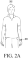
- FIG. 2A is a diagram illustrating an electronic device worn by a user according to one embodiment.
- an electronic device 201 can be worn by the user's body.
- the electronic device 201 may be implemented as various forms of wearable electronic devices that can be worn by a user 202, such as a smart watch, a smart band, a smart ring, wireless earphones, or smart glasses.
- the electronic device 201 may be a device that can be worn on the wrist of the user 202 or a device that can be worn on another part of the human body (e.g., an arm, a head, a thigh, etc.).
- the electronic device 201 may be implemented as various forms of electronic devices (e.g., a smartphone) that can perform a communication function, as well as a wearable electronic device.
- the electronic device 201 may be implemented in the same or similar manner as the electronic device 101 of FIG. 1 .
- FIG. 2B is a schematic block diagram illustrating a configuration of an electronic device according to one embodiment.
- the electronic device 201 may include a processor 220, a memory 230, a display 260, a sensor 270, and a communication circuit 290.
- the processor 220 may control the overall operation of the electronic device 201.
- the processor 220 may be implemented in the same or similar manner as the processor 120 of FIG. 1 .
- the senor 270 may include a first sensor 271 and/or a second sensor 272.
- the sensor 270 may be implemented in the same or similar manner as the sensor module 176 of FIG. 1 .
- the processor 220 may execute a first application (e.g., application 146 of FIG. 1 ) for measuring the user's biometric information.
- the processor 220 may display an execution screen of the first application on the display 260.
- the electronic device 201 may measure biometric information using the sensor 270 based on an input of the user 202 who requests biometric information measurement. Alternatively, according to one embodiment, the electronic device 201 may measure biometric information at predetermined designated time points based on an automatic measurement mode performed without an input from the user 202.
- the processor 220 may display the measured biometric information on the display 260 (e.g., the display module 160 of FIG. 1 ).
- the processor 220 may transmit the biometric information to an external electronic device through the communication circuit 290 (e.g., the communication module 190 of FIG. 1 ).
- the first sensor 271 may include a photoplethysmography (PPG) sensor.
- the processor 220 may acquire or measure biometric information including heart rate, oxygen saturation, stress, arrhythmia, and/or blood pressure of the user 202 based on the biometric signal acquired using the first sensor 271.
- the first sensor 271 may include a plurality of electrodes.
- the plurality of electrodes may be used to sense or detect a voltage corresponding to electrical resistance or a voltage corresponding to electrical conductivity by directly contacting the user's skin.
- the processor 220 may acquire a galvanic skin reflex (GSR), a bioelectrical impedance analysis (BIA) signal, and/or an electrocardiogram (ECG) signal using the first sensor 271.
- the processor 220 may measure biometric information including an electrocardiogram and/or body fat based on the biometric signal.
- the processor 220 may use the first sensor 271 to determine the contact state of the user's 202 skin with respect to the electronic device 201. For example, the processor 220 may receive at least some of light reflected from the user's skin through the PPG sensor included in the first sensor 271 to determine the contact state of the skin of the user 202 with respect to the first sensor 271. Alternatively, the processor 220 may also determine the contact state of the skin of the user 202 with respect to the first sensor 271 through the plurality of electrodes included in the first sensor 271.
- the processor 220 may determine whether the user 202 is in a state suitable for measuring biometric information using the second sensor 272. For example, the processor 220 may determine that the user 202 is not in the state suitable for measuring biometric information when it is determined that the movement of the user 202 is excessive compared to a designated condition. Alternatively, the processor 220 may determine that the user 202 is in the state suitable for measuring the biometric information when it is determined that the movement of the user 202 is not excessive compared to the designated condition.
- the processor 220 may acquire a first biometric signal for measuring the first biometric information of the user 202 based on a first configuration value through the first sensor 271.
- the first biometric signal may include a PPG signal.
- the processor 220 may acquire the first biometric signal by calculating a representative (e.g., maximum, minimum, median, or average) value of the biometric signal based on the biometric signal continuously (or discontinuously) acquired for a predetermined time.
- the first configuration value may include a configuration value related to at least one of the light output intensity, wavelength, and driving frequency of the first sensor 271, or time (or cycle) required to acquire the biometric signal.
- the above-described configuration value is a simple example, and embodiments of the present invention may not be limited thereto.
- the processor 220 may acquire first data on the first biometric information measured based on the first biometric signal.
- the first data may include at least one of a unique identification number of the first biometric information that is distinguished from other biometric information, a type of the first biometric information (e.g., heart rate, oxygen saturation, stress, arrhythmia, blood pressure, electrocardiogram, and/or body fat), a result value of the first biometric signal (e.g., heart rate per minute), a type of sensor used to acquire the first biometric signal (e.g., measurement using a PPG sensor or electrode), a time (or cycle) required to acquire the first biometric signal, a measurement type, a time point at which the first biometric signal is acquired, and a designated expiration time.
- a unique identification number of the first biometric information that is distinguished from other biometric information
- a type of the first biometric information e.g., heart rate, oxygen saturation, stress, arrhythmia, blood pressure, electrocardiogram, and/or body fat
- the measurement type may mean information indicating whether a first biometric signal-acquisition request is a first measurement request or a re-measurement request that is not the first.
- the first data may be stored in the memory 230 (e.g., the memory 130 of FIG. 1 ) in a token unit.
- the token may mean a designated unit for storing data.
- the processor 220 may store first data for the first biometric information in the memory 230.
- the processor 220 may determine whether the first data for the first biometric information has been previously acquired or stored. According to one embodiment, when it is determined that the first data for the first biometric information has not been acquired or stored, the processor 220 may acquire the first biometric signal for measuring the first biometric information of the user 202 based on the first configuration value of the first sensor 271.
- the processor 220 may determine whether re-measurement of the first biometric information is requested within a designated time (e.g., about 5 seconds) from a time point of acquiring the first data.
- a designated time e.g., about 5 seconds
- the designated time may mean a designated expiration time included in the first data.
- the processor 220 may acquire a second biometric signal for measuring the first biometric information of the user 202 based on a second configuration value that is different from the first configuration value.
- the second biometric signal and the first biometric signal may be substantially the same type of biometric signals.
- the second biometric signal may include a PPG signal.
- the second configuration value may mean a configuration value of the first sensor 271 for measuring the biometric signal more accurately than when measuring the first biometric signal.
- the processor 220 may determine whether the user is in a state suitable for measuring biometric information. For example, the processor 220 may use the first sensor 271 to identify the contact state of the skin of the user 202 with the electronic device 201. Alternatively, the processor 220 may use the second sensor 272 to identify the movement of the electronic device 201. Alternatively, when re-measurement of the first biometric information is requested within the designated time from the time point of acquiring or storing the first data, the processor 220 may stop other operations of the electronic device 201.
- the processor 220 may stop the execution of at least one application among other applications other than a first application (e.g., an application for measuring the user's biometric information) that may affect the measurement of the user's biometric information.
- a first application e.g., an application for measuring the user's biometric information
- the processor 220 may stop the transmission or reception operation of a signal that may affect the measurement of the user's biometric information.
- the processor 220 may determine that a predetermined condition for measuring biometric information is satisfied.
- the predetermined condition may mean a condition for determining whether the user is in a state suitable for measuring biometric information.
- the processor 220 may stop transmission or reception of a signal that may affect the acquisition of the biometric signal.
- the processor 220 may stop execution of at least one application other than the first application that may affect the acquisition of the biometric signal.
- the processor 220 may acquire a second biometric signal for measuring the first biometric information based on the first configuration value through the first sensor 271.
- the electronic device 201 may re-measure the user's biometric information (e.g., oxygen saturation) using a relatively more accurately sensed biometric signal (e.g., PPG signal). Through this, the electronic device 201 may provide relatively more accurately measured biometric information so that the user does not have to repeatedly re-measure the biometric information.
- biometric information e.g., oxygen saturation
- PPG signal e.g., PPG signal
- the operations of the electronic device described below can be performed by the processor 220. However, for the convenience of description, the operations performed by the processor 220 will be described as being performed by the electronic device 201.
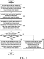
- FIG. 3 is a flowchart illustrating an operation method of the electronic device 201 according to one embodiment.
- respective operations may be performed sequentially, but are not necessarily performed sequentially.
- the order of each operation may be changed, and at least two operations may be performed in parallel.
- the electronic device 201 may acquire a first biometric signal (e.g., a PPG signal) for measuring first biometric information (e.g., heart rate, oxygen saturation) of the user based on a first configuration value through the first sensor 271 (e.g., the first sensor 271 of FIG. 2 ).
- a first biometric signal e.g., a PPG signal
- first biometric information e.g., heart rate, oxygen saturation
- the electronic device 201 may acquire or store first data for the first biometric information measured based on the first biometric signal.
- the first data may include information on a designated time (e.g., an expiration time).
- the electronic device 201 may determine whether re-measurement of the first biometric information is requested within a designated time from the time point of acquiring the first data. For example, when re-measurement of the first biometric information is requested, the electronic device 201 may determine the first data (or information on the designated time included in the first data). The electronic device 201 may determine whether re-measurement of the first biometric information is requested within the designated time included in the first data.
- the electronic device 201 may acquire a second biometric signal for measuring the first biometric information based on a second configuration value different from the first configuration value through the first sensor 271.
- the electronic device 201 may acquire second data for re-measurement of the first biometric information based on the second configuration value.
- the second configuration value may be a configuration value of the first sensor 271 for acquiring a biometric signal more accurately than the first configuration value.
- the second configuration value may include a value for changing the sensing time of the first sensor 271, the driving frequency of the first sensor 271, and the light output intensity of the first sensor 271.
- the electronic device 201 may acquire or sense the second biometric signal for a longer period of time than the acquisition or sensing time of the first biometric signal.
- the electronic device 201 may acquire the second biometric signal by operating the first sensor 271 at a driving frequency greater than the driving frequency of the first sensor for acquiring the first biometric signal.
- the electronic device 201 may use light output with an intensity greater than that of light output from the first sensor used to acquire the first biometric signal, thereby acquiring the second biometric signal.
- the electronic device 201 may acquire a second biometric signal for measuring the first biometric information based on the first configuration value through the first sensor 271. For example, the electronic device 201 may acquire the second biometric signal under substantially the same condition as when the first data is acquired.
- FIG. 4 is a flowchart illustrating an operation method of an electronic device according to one embodiment.
- respective operations may be performed sequentially, but are not necessarily performed sequentially.
- the order of each operation may be changed, and at least two operations may be performed in parallel.
- the electronic device 201 may acquire a first biometric signal for measuring first biometric information of a user based on a first configuration value through the first sensor 271.
- the electronic device 201 may acquire first data on the first biometric information measured based on the first biometric signal.
- the electronic device 201 may determine whether re-measurement of the first biometric information is requested within a designated time from the time point of acquiring the first data.
- the electronic device 201 may acquire a second biometric signal for measuring the first biometric information based on the first configuration value through the first sensor 271.
- the electronic device 201 may determine whether the electronic device 201 satisfies a predetermined condition.
- the predetermined condition may mean a condition indicating whether the electronic device 201 is in a state suitable for measuring biometric information from the user.
- the predetermined condition may include a condition related to the movement of the electronic device 201 and/or the contact state of the user's skin with the electronic device 201.
- the electronic device 201 may stop the execution of at least one application among applications (e.g., a phone application, a message application, a camera application, etc.) other than a first application executed at the time of re-measurement of the first biometric information.
- the electronic device 201 may stop the execution of other applications until the second biometric signal for measuring the first biometric information is acquired.
- the electronic device 201 may display a message (e.g., 710 of FIG. 7A ) indicating that execution of at least one application among applications other than the first application has been stopped, on the display 260.
- the electronic device 201 may stop measurement of at least one piece of biometric information among a plurality of pieces of biometric information (e.g., body fat information, oxygen saturation information, stress index information, etc.) other than the first biometric information at the time of re-measurement of the first biometric information (e.g., heart rate) when the predetermined condition is satisfied.
- the electronic device 201 may display a message (e.g., 720 of FIG. 7B ) indicating that measurement of at least one piece of biometric information among the plurality of pieces of biometric information other than the first biometric information has been stopped, on the display 260.
- the electronic device 201 may stop transmission or reception of another signal (e.g., a wireless communication signal) that may affect the quality of the second biometric signal.
- the electronic device 201 may display a message (e.g., 740 of FIG. 7D ) indicating that the transmission or reception of the other signal (e.g., wireless communication signal) has been stopped, on the display 260.
- the electronic device 201 is described as performing operations 406 to 407, at least some of the operations may be omitted. Alternatively, according to one embodiment, the electronic device 201 may perform operations 406 and 407 in parallel. Alternatively, according to one embodiment, the order of operations 406 and 407 may be changed. According to one embodiment, the electronic device 201 may control some operations of the electronic device 201 that may affect acquisition of the biometric signal in addition to operations 406 and 407. This may be performed within a range that can be easily implemented by those skilled in the art.
- the electronic device 201 may acquire a second biometric signal for measuring the first biometric information based on a second configuration value that is different from the first configuration value through the first sensor 271. According to one embodiment, specific operations for acquiring the second biometric signal based on the second configuration value will be described in detail later in FIG. 5 .
- the electronic device 201 may display guidance information on the display 260 without measuring the second biometric signal.
- the guidance information may include information related to the movement of the electronic device 201 or the contact state of the user's skin with the electronic device 201.
- the operation of displaying the guidance information is described in detail later in FIG. 6A and FIG. 6B .
- FIG. 5 is a flowchart illustrating an operation method of an electronic device for describing a second configuration value different from a first configuration value according to one embodiment.
- respective operations may be performed sequentially, but are not necessarily performed sequentially.
- the order of each operation may be changed, and at least two operations may be performed in parallel.
- the electronic device 201 may determine a second configuration value predetermined in the first sensor 271.
- the second configuration value may include a configuration value related to at least one of the light output intensity, wavelength, driving frequency, or sensing time (or cycle) required to acquire a biometric signal of the first sensor 271.
- the above-described configuration value is a simple example, and embodiments of the present invention may not be limited thereto.
- the electronic device 201 may increase the driving frequency of the first sensor 271.
- the driving frequency based on the second configuration value may be greater than the driving frequency based on the first configuration value.
- the electronic device 201 may improve the accuracy and reliability of the second biometric signal acquired through the first sensor 271.
- the electronic device 201 may increase the sensing time of the first sensor 271. For example, the sensing time based on the second configuration value may be longer than the sensing time based on the first configuration value. Through this, the electronic device 201 may improve the accuracy and reliability of the second biometric signal acquired through the first sensor 271.
- the electronic device 201 may increase the light output intensity of the first sensor 271.
- the light output intensity based on the second configuration value may be greater than the light output intensity based on the first configuration value.
- the electronic device 201 may be relatively less affected by the skin color, hairy skin, and/or tattoo of the user 202, and acquire more accurate biometric signals.
- the electronic device 201 has been described as performing operations 502 to 504, but some of the operations may be omitted. Alternatively, according to one embodiment, the electronic device 201 may perform operations 502 to 504 in parallel. Alternatively, according to one embodiment, the order of operations 502 to 504 may be changed.
- FIG. 6A is a flowchart illustrating an operation method of an electronic device for describing the predetermined condition of FIG. 4 according to one embodiment.
- respective operations may be performed sequentially, but are not necessarily performed sequentially.
- the order of each operation may be changed, and at least two operations may be performed in parallel.
- the electronic device 201 may identify the movement of the electronic device 201.
- the electronic device 201 may identify the movement of the electronic device 201 using a second sensor 272 (e.g., an acceleration sensor, a gyro sensor).
- a second sensor 272 e.g., an acceleration sensor, a gyro sensor.
- the electronic device 201 may determine whether the movement of the electronic device 201 satisfies a predetermined condition. According to one embodiment, the electronic device 201 may determine that the predetermined condition is satisfied when the movement (e.g., acceleration value) of the electronic device 201 is less than or equal to a predetermined value. Alternatively, the electronic device 201 may determine that the predetermined condition is not satisfied when the movement (e.g., acceleration value) of the electronic device 201 exceeds the predetermined value.
- the electronic device 201 may perform an operation of acquiring a second biometric signal for measuring the first biometric information in operation 603 when the predetermined condition is satisfied (operation 602-YES).
- the operation of acquiring the second biometric signal may include at least one of operations 406 to 408 of FIG. 4 .
- the operation of acquiring the second biosignal may include an operation of stopping execution of at least one application among applications other than a first application.
- the operation of acquiring the second biometric signal may include an operation of stopping measurement of at least one piece of biometric information among a plurality of pieces of biometric information other than the first biometric information.
- the operation of acquiring the second biometric signal may include an operation of stopping transmission or reception of a signal that may affect the quality of the second biometric signal.
- the operation of acquiring the second biometric signal may include an operation of acquiring a second biometric signal based on the second configuration value through the first sensor 271.
- the electronic device 201 may display guidance information on the display 260 without measuring the second biometric signal in operation 604.
- the electronic device 201 may display, on the display 260, a message (e.g., "Do not move while measuring biometric information") guiding the user to stop moving the electronic device 201.
- the electronic device 201 may output the guidance information as a voice.
- the electronic device 201 may output the guidance information as a predetermined vibration pattern.
- FIG. 6B is a flowchart illustrating an operation method of an electronic device for describing the predetermined condition of FIG. 4 according to one embodiment.
- respective operations may be performed sequentially, but are not necessarily performed sequentially.
- the order of each operation may be changed, and at least two operations may be performed in parallel.
- the electronic device 201 may identify the contact state of the user's skin with the electronic device 201.
- a biometric signal with noise may be acquired according to the contact state of the user's skin with the electronic device 201.
- the contact state may be identified based on a sensing value acquired using the first sensor 271.
- the electronic device 201 may identify the contact state based on at least one of a current value, a voltage value, an impedance value, or a conductivity value sensed by the first sensor 271.
- the electronic device 201 may determine whether the contact state of the user's skin with the electronic device 201 satisfies a predetermined condition. According to one embodiment, the electronic device 201 may determine that the predetermined condition is satisfied when the sensing value (e.g., PPG signal) received from the first sensor 271 is identified within a predetermined range (e.g., a measurable range of the first sensor 271) (e.g., a state in which the user's skin is in contact with the first sensor 271).
- a predetermined range e.g., a measurable range of the first sensor 271
- the electronic device 201 may determine that the predetermined condition is not satisfied when the sensing value from the first sensor 271 is identified to be outside the predetermined range (e.g., when the user's skin is not in contact with the first sensor 271). Alternatively, the electronic device 201 may determine that the predetermined condition is not satisfied even when the sensing value is not identified by the first sensor 271.
- the operation of acquiring the second biometric signal may include an operation of stopping transmission or reception of another signal that may affect the quality of the second biometric signal.
- the operation of acquiring the second biometric signal may include an operation of acquiring the second biometric signal based on the second configuration value through the first sensor 271.
- the electronic device 201 may display guidance information on the display 260 without measuring the second biometric signal.
- the electronic device 201 may display a message (e.g., 730 of FIG. 7C ), on the display 260, for guiding the user to adjust the contact state of the user's skin with the electronic device 201.
- the electronic device 201 may output the guidance information as a voice.
- the electronic device 201 may output the guidance information as a predetermined vibration pattern.
- FIGS. 7A, 7B, 7C, and 7D are diagrams illustrating a screen displayed by an electronic device according to one embodiment at the time of measuring biometric information.
- FIG. 7A is a diagram illustrating a screen in which the electronic device 201 according to one embodiment displays, on the display 260, a message indicating that execution of at least one among applications other than a first application has been stopped.
- the electronic device 201 may execute the first application and acquire a biometric signal for measuring or re-measuring user's biometric information. According to one embodiment, the electronic device 201 may stop the execution of applications other than the first application that is executed when measuring or re-measuring the user's biometric information.
- the electronic device 201 may display, on the display 260, a first message 710 indicating that the execution of applications other than the first application has been stopped (e.g., "Execution of other apps will be stopped until heart rate measurement is completed").
- the electronic device 201 may stop notifications (e.g., display on the display 260, sound, and/or vibration) from the other applications by stopping the execution of the other applications.
- the electronic device 201 may reduce changes in the psychological factors of the user 202 due to external influences, and measure more accurate biometric information.
- FIG. 7B is a diagram illustrating a screen in which the electronic device 201 according to one embodiment displays, on the display 260, a message indicating that measurement of at least one piece of biometric information among a plurality of pieces of biometric information other than the first biometric information has been stopped at the time of measuring the first biometric information.
- the electronic device 201 may measure or re-measure the first biometric information based on a user input requesting measurement of the first biometric information. According to one embodiment, the electronic device 201 may stop an automatic measurement mode in which biometric information is automatically measured at predetermined time intervals based on the user input requesting measurement of the first biometric information, and measure only the first biometric information.
- the electronic device 201 may display, on the display 260, a second message 720 (e.g., "Measurement of other biometric information will be stopped until heart rate measurement is completed.") indicating that measurement of at least one piece of biometric information among a plurality of pieces of biometric information other than the first biometric information has been stopped at the time of measuring or re-measuring the first biometric information.
- the electronic device 201 may stop the automatic measurement mode and display, on the display 260, a message (not shown) indicating that only the first biometric signal has been measured.
- FIG. 7C is a diagram illustrating a screen in which the electronic device 201 according to one embodiment displays, on the display 260, a message for guiding the user 202 to adjust the contact state of the user's skin with the electronic device 201.
- the electronic device 201 may identify the contact state between the electronic device 201 and the skin of the user 202 using the first sensor 271. According to one embodiment, the electronic device 201 may display, on the display 260, a third message 730 (e.g., "Move the wearable device to the right") that guides adjustment of the contact state of the skin of the user 202 with the electronic device 201 when a sensing value acquired using the first sensor 271 is out a predetermined range.
- a third message 730 e.g., "Move the wearable device to the right
- FIG. 7D is a diagram illustrating a screen in which the electronic device 201 according to one embodiment displays, on the display 260, a message notifying that communication with an external electronic device is stopped when measuring biometric information.
- the electronic device 201 may stop transmitting or receiving a signal that may affect the quality of the biometric signal.
- the electronic device 201 may stop a communication connection with an external electronic device (e.g., the electronic device 102 or 104 and the server 108 in FIG. 1 ) when measuring biometric information.
- the electronic device 201 may display, on the display 260, a fourth message notifying that communication with the external electronic device is stopped when measuring biometric information.
- the electronic device 201 may acquire a biometric signal by minimizing noise that may be generated due to a signal being transmitted or received.
- FIG. 8 is a flowchart illustrating an operation method of an electronic device according to one embodiment.
- respective operations may be performed sequentially, but are not necessarily performed sequentially.
- the order of each operation may be changed, and at least two operations may be performed in parallel.
- the electronic device 201 may acquire a first measurement result for the first biometric information.
- the first measurement result may include first biometric information (e.g., heart rate information) for a first biometric signal acquired based on a first configuration value and/or first biometric information (e.g., heart rate information) for a second biometric signal acquired based on a second configuration value.
- first biometric information e.g., heart rate information
- first biometric information e.g., heart rate information
- the electronic device 201 may determine that measurement of second biometric information (e.g., oxygen saturation information) different from the first biometric information is requested within a designated time from the time point of acquiring second data corresponding to the second biometric signal.
- the second data may include data on the first biometric information for the second biometric signal acquired based on the second configuration value.
- the second data may include at least one of a unique identification number, a type of the first biometric information (e.g., heart rate, oxygen saturation, stress, arrhythmia, blood pressure, electrocardiogram and/or body fat), a numerical result value of the first biometric information (e.g., heart rate 88 bpm), a type of sensor used to acquire the second biometric signal (e.g., PPG sensor, ECG sensor), a time (or cycle) required to acquire the second biometric signal, a measurement type (e.g., re-measurement), a time point at which the second biometric signal is acquired, or a specified expiration time.
- a type of the first biometric information e.g., heart rate, oxygen saturation, stress, arrhythmia, blood pressure, electrocardiogram and/or body fat
- a numerical result value of the first biometric information e.g., heart rate 88 bpm
- a type of sensor used to acquire the second biometric signal e.g., PPG sensor, E
- the specified expiration time included in the second data may be configured to be a longer time than the specified expiration time included in the first data.
- the electronic device 201 may display the first measurement result for the first biometric information and the second measurement result for the second biometric information on the display 260. According to one embodiment, the electronic device 201 may display the first measurement result including the first biometric information measured based on the first configuration value and/or the first biometric information measured based on the second configuration value together with the second measurement result for the second biometric information.
- the electronic device 201 may display only the second measurement result for the second biometric information on the display 260 when it is determined that measurement of the second biometric information is requested after the designated time from the time point of acquiring the second data.
- FIGS. 9A and 9B are diagrams illustrating a case in which the electronic device 201 according to one embodiment displays biometric information on the display 260.
- the electronic device 201 may display a first screen 910 including at least one piece of biometric information on the display 260.
- the at least one piece of biometric information may include data (e.g., first data) on a first biometric information measurement result or data (e.g., second data) on a re-measurement result for the first biometric information.
- the electronic device 201 may display at least one of the type of biometric information (e.g., heart rate ⁇ HR ⁇ ), the numerical result value of biometric information (e.g., average heart rate per minute), and information on the time point of acquiring the biometric information or measurement type on the first screen 910.
- the type of biometric information e.g., heart rate ⁇ HR ⁇
- the numerical result value of biometric information e.g., average heart rate per minute
- the electronic device 201 may visually distinguish the first data and the second data and display this on the first screen 910. For example, the electronic device 201 may display the second data in a predetermined color or display a predetermined object only on the second data.
- the electronic device 201 may display a second screen 920 including second data.
- the second screen 920 may include at least one of an average heart rate per minute, a graph showing a heart rate measurement result, a heart rate measurement time, a maximum heart rate, a minimum heart rate, or a driving frequency of the first sensor 271.
- the above-described screens 910 and 920 are merely examples, and embodiments of the present invention may not be limited thereto.
- the electronic device 201 may display a screen including at least one piece of biometric information on the display 260.
- the electronic device 201 may display a third screen 930 including first biometric information (e.g., blood pressure (BP), 119/77 mmHg) on the first biometric signal acquired based on the first configuration value, and first biometric information (e.g., BP, 120/82 mmHg) (e.g., the re-measurement result for the first biometric information) on the second biometric signal acquired based on the second configuration value.
- first biometric information e.g., blood pressure (BP), 119/77 mmHg
- first biometric information e.g., BP, 120/82 mmHg
- the electronic device 201 based on a user's input (e.g., touch input) 901 of selecting a predetermined object, the electronic device 201 my display a fourth screen 940 including the re-measurement result (e.g., with 120/82 mmHg) for the first biometric information (e.g., BP information), second biometric information (e.g., stress index information), third biometric information (e.g., heart rate (HR) information), fourth biometric information (e.g., glucose information), and fifth biometric information (e.g., oxygen saturation (SpO 2 ) information).
- the first biometric information e.g., BP information
- second biometric information e.g., stress index information
- third biometric information e.g., heart rate (HR) information
- fourth biometric information e.g., glucose information
- fifth biometric information e.g., oxygen saturation (SpO 2 ) information.
- the biometric information may be listed in the order in which the biometric information was measured in time sequence (e.g., 1)->2)->3)->4)) and displayed on a fourth screen 940.
- the present invention is not limited thereto, and the biometric information may be listed and displayed in various ways.
- the third data corresponding to the biometric signal acquired for measuring the second biometric information may have a longer designated expiration time than the second data.
- the fourth data corresponding to the biometric signal acquired for measuring the third biometric information may have a longer designated expiration time than the third data.
- the electronic device 201 may transmit the biometric information to an external electronic device through the communication circuit 290.
- the external electronic device may display the received biometric information on the display 260.
- An electronic device may include a first sensor, a memory, and at least one processor.
- the memory may store at least one instruction that, when executed by the at least one processor, causes the electronic device to acquire a first biometric signal for measuring first biometric information of a user based on a first configuration value through the first sensor.
- the memory may store at least one instruction that, when executed by the at least one processor, causes the electronic device to acquire first data on the first biometric information measured based on the first biometric signal.
- the memory may store at least one instruction that, when executed by the at least one processor, causes the electronic device to determine whether re-measurement of the first biometric information is requested within a designated time from the time point of acquiring the first data, when re-measurement of the first biometric information is requested.
- the memory may store at least one instruction that, when executed by the at least one processor, causes the electronic device to acquire a second biometric signal for measuring the first biometric information based on a second configuration value different from the first configuration value through the first sensor based on the determination that re-measurement of the first biometric information is requested within the designated time from the time point of acquiring the first data.
- the electronic device may further include a second sensor.
- the at least one instruction may cause, when executed by the at least one processor, the electronic device to identify a measurement state of the first biometric information using the first sensor or the second sensor.
- the at least one instruction according to one embodiment may cause, when executed by the at least one processor, the electronic device to acquire the second biometric signal according to the identification result.
- the at least one instruction may cause, when executed by the at least one processor, the electronic device to identify a contact state of the user's skin with the electronic device using the first sensor.
- the at least one instruction may cause, when executed by the at least one processor, the electronic device to prevent the acquisition of the second biometric signal when the contact state of the user's skin does not satisfy a predetermined condition.
- the at least one instruction may cause, when executed by the at least one processor, the electronic device to identify a movement of the electronic device using the second sensor.
- the at least one instruction may cause, when executed by the at least one processor, the electronic device to prevent the acquisition of the second biometric signal when the movement of the electronic device does not satisfy a predetermined condition.
- the at least one instruction may cause, when executed by the at least one processor, the electronic device to stop transmission or reception of a signal that affects the quality of the second biometric signal based on the determination that re-measurement of the first biometric information is requested within the designated time from the time point of acquiring the first data.
- the at least one instruction may cause, when executed by the at least one processor, the electronic device to start re-measurement of the first biometric information of the user based on execution of a first application installed in the electronic device.
- the at least one instruction may cause, when executed by the at least one processor, the electronic device to stop execution of at least one application among other applications installed in the electronic device when re-measurement of the first biometric information is started.
- the at least one instruction may cause, when executed by the at least one processor, the electronic device to acquire the second biometric signal for a longer time than the time point of acquiring the first biometric signal.
- the at least one instruction may cause, when executed by the at least one processor, the electronic device to operate the first sensor at a driving frequency greater than a driving frequency of the first sensor for acquiring the first biometric signal.
- the at least one instruction may cause, when executed by the at least one processor, the electronic device to acquire the second biometric signal using light output with an intensity greater than an intensity of light output from the first sensor used to acquire the first biometric signal.
- the at least one instruction may cause, when executed by the at least one processor, the electronic device to determine whether re-measurement of the second biometric information different from the first biometric information is requested within a designated time from the time point of acquiring the second data corresponding to the second biometric signal, when re-measurement of the second biometric information is requested.
- the at least one instruction may cause, when executed by the at least one processor, the electronic device to display a first measurement result for the first biometric information and a second measurement result for the second biometric information on the display, when measurement of the second biometric information is requested within the designated time from the time point of acquiring the second data.
- An operation method of an electronic device may include acquiring a first biometric signal for measuring first biometric information of a user based on a first configuration value through a first sensor included in the electronic device.
- the operation method of the electronic device may include acquiring first data on the first biometric information measured based on the first biometric signal.
- the operation method of the electronic device may include determining whether re-measurement of the first biometric information is requested within a designated time from the time point of acquiring the first data, when re-measurement of the first biometric information is requested.
- the operation method of the electronic device may include acquiring a second biometric signal for measuring the first biometric information based on a second configuration value different from the first configuration value through the first sensor based on the determination that re-measurement of the first biometric information is requested within the designated time from the time point of acquiring the first data.
- the operation method of the electronic device may include identifying a measurement state of the first biometric information using the first sensor of a second sensor included in the electronic device.
- the operation method of the electronic device may include acquiring the second biometric signal according to a result of the identifying.
- the operation method of the electronic device may include identifying a contact state of the user's skin with the electronic device using the first sensor.
- the operation method of the electronic device may include preventing the second biometric signal from being acquired when the contact state of the user's skin does not satisfy a predetermined condition.
- the operation method of the electronic device may include identifying a movement of the electronic device using the second sensor.
- the operation method of the electronic device may include preventing the second biometric signal from being acquired when the movement of the electronic device does not satisfy the predetermined condition.
- the operation method of the electronic device may include stopping transmission or reception of a signal that affects the quality of the second biometric signal based on the determining that re-measurement of the first biometric information is requested within the designated time from the time point of acquiring the first data.
- the operation method of the electronic device may include starting re-measurement of the first biometric information of the user based on execution of a first application installed in the electronic device.
- the operation method of the electronic device may include stopping execution of at least one application among other applications installed in the electronic device when re-measurement of the first biometric information is started.
- the operation method of the electronic device may include operating the first sensor at a driving frequency greater than a driving frequency of the first sensor for acquiring the first biometric signal.
- the operation method of the electronic device may include measuring the second biometric signal using light output with an intensity greater than an intensity of light output from the first sensor used to acquire the first biometric signal.
- the operation method of the electronic device may include determining whether re-measurement of the second biometric information different from the first biometric information is requested within a designated time from the time point of acquiring the second data corresponding to the second biometric signal, when re-measurement of the second biometric information is requested.
- a non-transitory recording medium may store at least one instruction capable of executing an operation of acquiring a first biometric signal for measuring first biometric information of a user based on a first configuration value through a first sensor included in an electronic device.
- the non-transitory recording medium may store at least one instruction capable of executing an operation of acquiring first data on the first biometric information measured based on the first biometric signal.
- the non-transitory recording medium may store at least one instruction capable of executing an operation of determining whether re-measurement of the first biometric information is requested within a designated time from the time point of acquiring the first data, when re-measurement of the first biometric information is requested.
- the non-transitory recording medium may store at least one instruction capable of executing an operation of acquiring a second biometric signal for measuring the first biometric information based on a second configuration value different from the first configuration value through the first sensor based on the determination that re-measurement of the first biometric information is requested within the designated time from the time point of acquiring the first data.
- the electronic device may be one of various types of electronic devices.
- the electronic devices may include, for example, a portable communication device (e.g., a smartphone), a computer device, a portable multimedia device, a portable medical device, a camera, a wearable device, or a home appliance. According to an embodiment of the disclosure, the electronic devices are not limited to those described above.
- each of such phrases as “A or B,” “at least one of A and B,” “at least one of A or B,” “A, B, or C,” “at least one of A, B, and C,” and “at least one of A, B, or C,” may include any one of, or all possible combinations of the items enumerated together in a corresponding one of the phrases.
- such terms as “1st” and “2nd,” or “first” and “second” may be used to simply distinguish a corresponding component from another, and does not limit the components in other aspect (e.g., importance or order).
- an element e.g., a first element
- the element may be coupled with the other element directly (e.g., wiredly), wirelessly, or via a third element.
- module may include a unit implemented in hardware, software, or firmware, and may interchangeably be used with other terms, for example, “logic,” “logic block,” “part,” or “circuitry”.
- a module may be a single integral component, or a minimum unit or part thereof, adapted to perform one or more functions.
- the module may be implemented in a form of an application-specific integrated circuit (ASIC).
- ASIC application-specific integrated circuit
- Various embodiments as set forth herein may be implemented as software (e.g., the program 140) including one or more instructions that are stored in a storage medium (e.g., internal memory 136 or external memory 138) that is readable by a machine (e.g., the electronic device 101, 401).
- a processor e.g., the processor 120 of the machine (e.g., the electronic device 101, 401) may invoke at least one of the one or more instructions stored in the storage medium, and execute it, with or without using one or more other components under the control of the processor. This allows the machine to be operated to perform at least one function according to the at least one instruction invoked.
- the one or more instructions may include a code generated by a complier or a code executable by an interpreter.
- the machine-readable storage medium may be provided in the form of a non-transitory storage medium.
- a method may be included and provided in a computer program product.
- the computer program product may be traded as a product between a seller and a buyer.
- the computer program product may be distributed in the form of a machine-readable storage medium (e.g., compact disc read only memory (CD-ROM)), or be distributed (e.g., downloaded or uploaded) online via an application store (e.g., PlayStore TM ), or between two user devices (e.g., smart phones) directly. If distributed online, at least part of the computer program product may be temporarily generated or at least temporarily stored in the machine-readable storage medium, such as memory of the manufacturer's server, a server of the application store, or a relay server.
- CD-ROM compact disc read only memory
- an application store e.g., PlayStore TM
- two user devices e.g., smart phones
- each component e.g., a module or a program of the above-described components may include a single entity or multiple entities, and some of the multiple entities may be separately disposed in different components. According to various embodiments, one or more of the above-described components may be omitted, or one or more other components may be added. Alternatively or additionally, a plurality of components (e.g., modules or programs) may be integrated into a single component. In such a case, according to various embodiments, the integrated component may still perform one or more functions of each of the plurality of components in the same or similar manner as they are performed by a corresponding one of the plurality of components before the integration.
- operations performed by the module, the program, or another component may be carried out sequentially, in parallel, repeatedly, or heuristically, or one or more of the operations may be executed in a different order or omitted, or one or more other operations may be added.
Landscapes
- Health & Medical Sciences (AREA)
- Life Sciences & Earth Sciences (AREA)
- Engineering & Computer Science (AREA)
- Physics & Mathematics (AREA)
- Veterinary Medicine (AREA)
- Biomedical Technology (AREA)
- Heart & Thoracic Surgery (AREA)
- Medical Informatics (AREA)
- Molecular Biology (AREA)
- Surgery (AREA)
- Animal Behavior & Ethology (AREA)
- General Health & Medical Sciences (AREA)
- Public Health (AREA)
- Biophysics (AREA)
- Pathology (AREA)
- Physiology (AREA)
- Cardiology (AREA)
- Artificial Intelligence (AREA)
- Computer Vision & Pattern Recognition (AREA)
- Psychiatry (AREA)
- Signal Processing (AREA)
- Pulmonology (AREA)
- Computer Networks & Wireless Communication (AREA)
- Spectroscopy & Molecular Physics (AREA)
- Optics & Photonics (AREA)
- Multimedia (AREA)
- Measurement Of The Respiration, Hearing Ability, Form, And Blood Characteristics Of Living Organisms (AREA)
- Telephone Function (AREA)
Applications Claiming Priority (3)
| Application Number | Priority Date | Filing Date | Title |
|---|---|---|---|
| KR20220107189 | 2022-08-25 | ||
| KR1020220116422A KR20240028888A (ko) | 2022-08-25 | 2022-09-15 | 생체 정보를 측정하는 전자 장치 및 이의 동작 방법 |
| PCT/KR2023/008022 WO2024043465A1 (ko) | 2022-08-25 | 2023-06-12 | 생체 정보를 측정하는 전자 장치 및 이의 동작 방법 |
Publications (2)
| Publication Number | Publication Date |
|---|---|
| EP4544996A1 true EP4544996A1 (de) | 2025-04-30 |
| EP4544996A4 EP4544996A4 (de) | 2025-05-07 |
Family
ID=90013350
Family Applications (1)
| Application Number | Title | Priority Date | Filing Date |
|---|---|---|---|
| EP23857503.9A Pending EP4544996A4 (de) | 2022-08-25 | 2023-06-12 | Elektronische vorrichtung zur messung biometrischer informationen und betriebsverfahren dafür |
Country Status (3)
| Country | Link |
|---|---|
| US (1) | US20250143651A1 (de) |
| EP (1) | EP4544996A4 (de) |
| WO (1) | WO2024043465A1 (de) |
Family Cites Families (10)
| Publication number | Priority date | Publication date | Assignee | Title |
|---|---|---|---|---|
| JP4613280B2 (ja) * | 2006-04-07 | 2011-01-12 | コニカミノルタセンシング株式会社 | 睡眠時無呼吸症候群スクリーニングシステム及びその動作プログラム |
| KR101372120B1 (ko) * | 2011-06-23 | 2014-03-07 | 현대자동차주식회사 | 차량 운전자의 생체정보 획득 장치 및 그 방법 |
| CN105852841B (zh) * | 2013-06-03 | 2019-06-18 | 飞比特公司 | 心率数据收集 |
| US20160029970A1 (en) * | 2014-07-31 | 2016-02-04 | Lg Cns Co., Ltd. | Apparatus and method for determining validity of biological data |
| EP3066977A1 (de) * | 2015-03-13 | 2016-09-14 | Biowatch SA | Biometrischer sensor in einer Armbanduhr oder einem Armband zur Detektion von Handgelenk-Blutgefässen |
| KR102322029B1 (ko) * | 2015-03-27 | 2021-11-04 | 삼성전자주식회사 | 생체 정보 획득 방법 및 이를 위한 장치 |
| KR102407094B1 (ko) * | 2017-07-25 | 2022-06-08 | 삼성전자주식회사 | 생체정보 측정 장치 및 방법 |
| KR102588906B1 (ko) * | 2017-12-01 | 2023-10-13 | 삼성전자주식회사 | 생체 신호 품질 평가 장치 및 방법 |
| KR102833417B1 (ko) * | 2019-10-21 | 2025-07-14 | 삼성전자주식회사 | 다중 디바이스 간의 생리적 데이터 통합 및 도시화 장치 및 그 방법 |
| US12446833B2 (en) * | 2020-08-26 | 2025-10-21 | Samsung Electronics Co., Ltd. | Method for predicting failure of bio-information estimation and apparatus for estimating bio-information |
-
2023
- 2023-06-12 EP EP23857503.9A patent/EP4544996A4/de active Pending
- 2023-06-12 WO PCT/KR2023/008022 patent/WO2024043465A1/ko not_active Ceased
-
2025
- 2025-01-13 US US19/018,465 patent/US20250143651A1/en active Pending
Also Published As
| Publication number | Publication date |
|---|---|
| EP4544996A4 (de) | 2025-05-07 |
| US20250143651A1 (en) | 2025-05-08 |
| WO2024043465A1 (ko) | 2024-02-29 |
Similar Documents
| Publication | Publication Date | Title |
|---|---|---|
| US12521063B2 (en) | Wearable device and method for measuring biometric information | |
| EP4295759B1 (de) | Tragbare elektronische vorrichtung zur blutdruckmessung und betriebsverfahren dafür | |
| US11730377B2 (en) | Electronic device and method for providing information on cardiovascular state of user | |
| EP4169447A1 (de) | Verfahren zur erfassung biometrischer informationen und elektronische vorrichtung dafür | |
| US20250072842A1 (en) | Electronic device for displaying information related to wearable electronic device, operation method thereof, and recording medium | |
| EP4316612A1 (de) | Verfahren zur bereitstellung von trainingsdaten mittels mehrerer elektronischer vorrichtungen und elektronische vorrichtung dafür | |
| US20230118067A1 (en) | Electronic device and method to measure bioelectrical impedance | |
| US20210257086A1 (en) | Electronic device and method for recognizing context thereof | |
| US12465262B2 (en) | Electronic device for measuring electrocardiogram and operation method in electronic device | |
| KR20240028888A (ko) | 생체 정보를 측정하는 전자 장치 및 이의 동작 방법 | |
| US12594034B2 (en) | Wearable device and method for measuring biometric information | |
| US20250143651A1 (en) | Electronic device for measuring biometric information and operation method thereof | |
| EP4385394A1 (de) | Tragbare vorrichtung mit körpertemperatursensor, verfahren und nichttransitorisches computerlesbares speichermedium | |
| EP4152720A1 (de) | Datenübertragungsverfahren und elektronische vorrichtung zur unterstützung davon | |
| US12458279B2 (en) | Method for detecting biometric information and electronic device supporting the same | |
| KR20220152633A (ko) | 생체 정보 검출 방법 및 이를 지원하는 전자 장치 | |
| US12150780B2 (en) | Electronic device and method for providing individualized guide based on blood pressure related information | |
| US20240221930A1 (en) | Electronic device and method for displaying screen on basis of acquired data | |
| EP4666939A1 (de) | Tragbare vorrichtung zur überwachung von körperwasser, elektronische vorrichtung und betriebsverfahren dafür | |
| EP4728978A1 (de) | Verfahren und elektronische vorrichtung zur messung von herzschlägen und speichermedium | |
| US20250169705A1 (en) | Electronic device and method for generating data related to heart rate using the same | |
| US20260000336A1 (en) | First wearable electronic device for acquiring signal including noise corresponding to movement of user, electronic device for analyzing signal, and operating method of electronic device | |
| KR20250089370A (ko) | 혈당값에 관련된 캘리브레이션 데이터를 획득하는 웨어러블 전자 장치, 이의 동작 방법, 및 저장 매체 | |
| KR20250032728A (ko) | 웨어러블 전자 장치와 관련된 정보를 표시하는 전자 장치, 이의 동작 방법, 및 기록매체 | |
| KR20250023230A (ko) | 복수의 전자 장치들을 이용한 운동 정보 측정 방법 및 장치 |
Legal Events
| Date | Code | Title | Description |
|---|---|---|---|
| STAA | Information on the status of an ep patent application or granted ep patent |
Free format text: STATUS: THE INTERNATIONAL PUBLICATION HAS BEEN MADE |
|
| PUAI | Public reference made under article 153(3) epc to a published international application that has entered the european phase |
Free format text: ORIGINAL CODE: 0009012 |
|
| STAA | Information on the status of an ep patent application or granted ep patent |
Free format text: STATUS: REQUEST FOR EXAMINATION WAS MADE |
|
| 17P | Request for examination filed |
Effective date: 20250122 |
|
| AK | Designated contracting states |
Kind code of ref document: A1 Designated state(s): AL AT BE BG CH CY CZ DE DK EE ES FI FR GB GR HR HU IE IS IT LI LT LU LV MC ME MK MT NL NO PL PT RO RS SE SI SK SM TR |
|
| A4 | Supplementary search report drawn up and despatched |
Effective date: 20250404 |
|
| RIC1 | Information provided on ipc code assigned before grant |
Ipc: A61B 5/1455 20060101ALI20250331BHEP Ipc: A61B 5/00 20060101ALI20250331BHEP Ipc: A61B 5/024 20060101AFI20250331BHEP |
|
| DAV | Request for validation of the european patent (deleted) | ||
| DAX | Request for extension of the european patent (deleted) | ||
| STAA | Information on the status of an ep patent application or granted ep patent |
Free format text: STATUS: EXAMINATION IS IN PROGRESS |
|
| 17Q | First examination report despatched |
Effective date: 20260325 |