EP4545022A2 - Instrument chirurgical à ultrasons avec éléments de remplacement de lame - Google Patents
Instrument chirurgical à ultrasons avec éléments de remplacement de lame Download PDFInfo
- Publication number
- EP4545022A2 EP4545022A2 EP25151871.8A EP25151871A EP4545022A2 EP 4545022 A2 EP4545022 A2 EP 4545022A2 EP 25151871 A EP25151871 A EP 25151871A EP 4545022 A2 EP4545022 A2 EP 4545022A2
- Authority
- EP
- European Patent Office
- Prior art keywords
- waveguide
- coupling member
- shaft assembly
- clamp arm
- blade
- Prior art date
- Legal status (The legal status is an assumption and is not a legal conclusion. Google has not performed a legal analysis and makes no representation as to the accuracy of the status listed.)
- Pending
Links
Images












Classifications
-
- A—HUMAN NECESSITIES
- A61—MEDICAL OR VETERINARY SCIENCE; HYGIENE
- A61B—DIAGNOSIS; SURGERY; IDENTIFICATION
- A61B17/00—Surgical instruments, devices or methods
- A61B17/32—Surgical cutting instruments
- A61B17/320068—Surgical cutting instruments using mechanical vibrations, e.g. ultrasonic
- A61B17/320092—Surgical cutting instruments using mechanical vibrations, e.g. ultrasonic with additional movable means for clamping or cutting tissue, e.g. with a pivoting jaw
-
- A—HUMAN NECESSITIES
- A61—MEDICAL OR VETERINARY SCIENCE; HYGIENE
- A61N—ELECTROTHERAPY; MAGNETOTHERAPY; RADIATION THERAPY; ULTRASOUND THERAPY
- A61N7/00—Ultrasound therapy
- A61N7/02—Localised ultrasound hyperthermia
-
- A—HUMAN NECESSITIES
- A61—MEDICAL OR VETERINARY SCIENCE; HYGIENE
- A61B—DIAGNOSIS; SURGERY; IDENTIFICATION
- A61B17/00—Surgical instruments, devices or methods
- A61B2017/00367—Details of actuation of instruments, e.g. relations between pushing buttons, or the like, and activation of the tool, working tip, or the like
- A61B2017/00389—Button or wheel for performing multiple functions, e.g. rotation of shaft and end effector
-
- A—HUMAN NECESSITIES
- A61—MEDICAL OR VETERINARY SCIENCE; HYGIENE
- A61B—DIAGNOSIS; SURGERY; IDENTIFICATION
- A61B17/00—Surgical instruments, devices or methods
- A61B2017/0042—Surgical instruments, devices or methods with special provisions for gripping
-
- A—HUMAN NECESSITIES
- A61—MEDICAL OR VETERINARY SCIENCE; HYGIENE
- A61B—DIAGNOSIS; SURGERY; IDENTIFICATION
- A61B17/00—Surgical instruments, devices or methods
- A61B2017/0042—Surgical instruments, devices or methods with special provisions for gripping
- A61B2017/00455—Orientation indicators, e.g. recess on the handle
-
- A—HUMAN NECESSITIES
- A61—MEDICAL OR VETERINARY SCIENCE; HYGIENE
- A61B—DIAGNOSIS; SURGERY; IDENTIFICATION
- A61B17/00—Surgical instruments, devices or methods
- A61B2017/00477—Coupling
-
- A—HUMAN NECESSITIES
- A61—MEDICAL OR VETERINARY SCIENCE; HYGIENE
- A61B—DIAGNOSIS; SURGERY; IDENTIFICATION
- A61B17/00—Surgical instruments, devices or methods
- A61B2017/00526—Methods of manufacturing
-
- A—HUMAN NECESSITIES
- A61—MEDICAL OR VETERINARY SCIENCE; HYGIENE
- A61B—DIAGNOSIS; SURGERY; IDENTIFICATION
- A61B17/00—Surgical instruments, devices or methods
- A61B17/28—Surgical forceps
- A61B17/29—Forceps for use in minimally invasive surgery
- A61B2017/2926—Details of heads or jaws
-
- A—HUMAN NECESSITIES
- A61—MEDICAL OR VETERINARY SCIENCE; HYGIENE
- A61B—DIAGNOSIS; SURGERY; IDENTIFICATION
- A61B17/00—Surgical instruments, devices or methods
- A61B17/28—Surgical forceps
- A61B17/29—Forceps for use in minimally invasive surgery
- A61B2017/2926—Details of heads or jaws
- A61B2017/2931—Details of heads or jaws with releasable head
-
- A—HUMAN NECESSITIES
- A61—MEDICAL OR VETERINARY SCIENCE; HYGIENE
- A61B—DIAGNOSIS; SURGERY; IDENTIFICATION
- A61B17/00—Surgical instruments, devices or methods
- A61B17/28—Surgical forceps
- A61B17/29—Forceps for use in minimally invasive surgery
- A61B2017/2947—Pivots
-
- A—HUMAN NECESSITIES
- A61—MEDICAL OR VETERINARY SCIENCE; HYGIENE
- A61B—DIAGNOSIS; SURGERY; IDENTIFICATION
- A61B17/00—Surgical instruments, devices or methods
- A61B17/32—Surgical cutting instruments
- A61B17/320068—Surgical cutting instruments using mechanical vibrations, e.g. ultrasonic
- A61B17/320092—Surgical cutting instruments using mechanical vibrations, e.g. ultrasonic with additional movable means for clamping or cutting tissue, e.g. with a pivoting jaw
- A61B2017/320093—Surgical cutting instruments using mechanical vibrations, e.g. ultrasonic with additional movable means for clamping or cutting tissue, e.g. with a pivoting jaw additional movable means performing cutting operation
-
- A—HUMAN NECESSITIES
- A61—MEDICAL OR VETERINARY SCIENCE; HYGIENE
- A61B—DIAGNOSIS; SURGERY; IDENTIFICATION
- A61B17/00—Surgical instruments, devices or methods
- A61B17/32—Surgical cutting instruments
- A61B17/320068—Surgical cutting instruments using mechanical vibrations, e.g. ultrasonic
- A61B17/320092—Surgical cutting instruments using mechanical vibrations, e.g. ultrasonic with additional movable means for clamping or cutting tissue, e.g. with a pivoting jaw
- A61B2017/320094—Surgical cutting instruments using mechanical vibrations, e.g. ultrasonic with additional movable means for clamping or cutting tissue, e.g. with a pivoting jaw additional movable means performing clamping operation
-
- A—HUMAN NECESSITIES
- A61—MEDICAL OR VETERINARY SCIENCE; HYGIENE
- A61B—DIAGNOSIS; SURGERY; IDENTIFICATION
- A61B18/00—Surgical instruments, devices or methods for transferring non-mechanical forms of energy to or from the body
- A61B2018/00571—Surgical instruments, devices or methods for transferring non-mechanical forms of energy to or from the body for achieving a particular surgical effect
- A61B2018/00589—Coagulation
-
- A—HUMAN NECESSITIES
- A61—MEDICAL OR VETERINARY SCIENCE; HYGIENE
- A61B—DIAGNOSIS; SURGERY; IDENTIFICATION
- A61B18/00—Surgical instruments, devices or methods for transferring non-mechanical forms of energy to or from the body
- A61B2018/00571—Surgical instruments, devices or methods for transferring non-mechanical forms of energy to or from the body for achieving a particular surgical effect
- A61B2018/00619—Welding
-
- A—HUMAN NECESSITIES
- A61—MEDICAL OR VETERINARY SCIENCE; HYGIENE
- A61B—DIAGNOSIS; SURGERY; IDENTIFICATION
- A61B18/00—Surgical instruments, devices or methods for transferring non-mechanical forms of energy to or from the body
- A61B2018/00571—Surgical instruments, devices or methods for transferring non-mechanical forms of energy to or from the body for achieving a particular surgical effect
- A61B2018/0063—Sealing
-
- A—HUMAN NECESSITIES
- A61—MEDICAL OR VETERINARY SCIENCE; HYGIENE
- A61B—DIAGNOSIS; SURGERY; IDENTIFICATION
- A61B90/00—Instruments, implements or accessories specially adapted for surgery or diagnosis and not covered by any of the groups A61B1/00 - A61B50/00, e.g. for luxation treatment or for protecting wound edges
- A61B90/08—Accessories or related features not otherwise provided for
- A61B2090/0807—Indication means
- A61B2090/0808—Indication means for indicating correct assembly of components, e.g. of the surgical apparatus
-
- A—HUMAN NECESSITIES
- A61—MEDICAL OR VETERINARY SCIENCE; HYGIENE
- A61B—DIAGNOSIS; SURGERY; IDENTIFICATION
- A61B90/00—Instruments, implements or accessories specially adapted for surgery or diagnosis and not covered by any of the groups A61B1/00 - A61B50/00, e.g. for luxation treatment or for protecting wound edges
- A61B90/08—Accessories or related features not otherwise provided for
- A61B2090/0807—Indication means
- A61B2090/0811—Indication means for the position of a particular part of an instrument with respect to the rest of the instrument, e.g. position of the anvil of a stapling instrument
-
- A—HUMAN NECESSITIES
- A61—MEDICAL OR VETERINARY SCIENCE; HYGIENE
- A61B—DIAGNOSIS; SURGERY; IDENTIFICATION
- A61B90/00—Instruments, implements or accessories specially adapted for surgery or diagnosis and not covered by any of the groups A61B1/00 - A61B50/00, e.g. for luxation treatment or for protecting wound edges
- A61B90/08—Accessories or related features not otherwise provided for
- A61B2090/0813—Accessories designed for easy sterilising, i.e. re-usable
-
- A—HUMAN NECESSITIES
- A61—MEDICAL OR VETERINARY SCIENCE; HYGIENE
- A61N—ELECTROTHERAPY; MAGNETOTHERAPY; RADIATION THERAPY; ULTRASOUND THERAPY
- A61N7/00—Ultrasound therapy
- A61N2007/0056—Beam shaping elements
Definitions
- a variety of surgical instruments include an end effector having a blade element that vibrates at ultrasonic frequencies to cut and/or seal tissue (e.g., by denaturing proteins in tissue cells). These instruments include one or more piezoelectric elements that convert electrical power into ultrasonic vibrations, which are communicated along an acoustic waveguide to the blade element. The precision of cutting and coagulation may be controlled by the operator's technique and adjusting the power level, blade edge angle, tissue traction, and blade pressure.
- Some ultrasonic surgical instruments may include a cordless transducer such as that disclosed in U.S. Pub. No. 2012/0112687, entitled “Recharge System for Medical Devices,” published May 10, 2012 ., the disclosure of which is incorporated by reference herein; U.S. Pub. No. 2012/0116265, entitled “Surgical Instrument with Charging Devices,” published May 10, 2012 , the disclosure of which is incorporated by reference herein; and/or U.S. Pat. App. No. 61/410,603, filed November 5, 2010 , entitled “Energy-Based Surgical Instruments,” the disclosure of which is incorporated by reference herein.
- ultrasonic surgical instruments may include an articulating shaft section.
- Examples of such ultrasonic surgical instruments are disclosed in U.S. Pub. No. 2014/0005701, published January 2, 2014 , entitled “Surgical Instruments with Articulating Shafts,” the disclosure of which is incorporated by reference herein; and U.S. Pub. No. 2014/0114334, published April 24, 2014 , entitled “Flexible Harmonic Waveguides/Blades for Surgical Instruments,” the disclosure of which is incorporated by reference herein.
- proximal and distal are defined herein relative to a human or robotic operator of the surgical instrument.
- proximal refers the position of an element closer to the human or robotic operator of the surgical instrument and further away from the surgical end effector of the surgical instrument.
- distal refers to the position of an element closer to the surgical end effector of the surgical instrument and further away from the human or robotic operator of the surgical instrument.
- FIGS. 1-3 show an exemplary ultrasonic surgical instrument (10) that is configured to be used in minimally invasive surgical procedures (e.g., via a trocar or other small diameter access port, etc.).
- instrument (10) is operable to cut tissue and seal or weld tissue (e.g., a blood vessel, etc.) substantially simultaneously.
- Instrument (10) of this example comprises a disposable assembly (100) and a reusable assembly (200). The distal portion of reusable assembly (200) is configured to removably receive the proximal portion of disposable assembly (100), as seen in FIGS. 2-3 , to form instrument (10).
- assemblies (100, 200) are coupled together to form instrument (10) before a surgical procedure, the assembled instrument (10) is used to perform the surgical procedure, and then assemblies (100, 200) are decoupled from each other for further processing.
- disposable assembly (100) is immediately disposed of while reusable assembly (200) is sterilized and otherwise processed for re-use.
- reusable assembly (200) may be sterilized in a conventional relatively low temperature, relatively low pressure, hydrogen peroxide sterilization process.
- reusable assembly (200) may be sterilized using any other suitable systems and techniques (e.g., autoclave, etc.).
- reusable assembly (200) may be sterilized and reused approximately 100 times.
- reusable assembly (200) may be subject to any other suitable life cycle.
- reusable assembly (200) may be disposed of after a single use, if desired.
- disposable assembly (100) is referred to herein as being "disposable,” it should be understood that, in some instances, disposable assembly (100) may also be sterilized and otherwise processed for re-use.
- disposable assembly (100) may be sterilized and reused approximately 2-30 times, using any suitable systems and techniques.
- disposable assembly (100) may be subject to any other suitable life cycle.
- Disposable assembly (100) of the present example comprises a body portion (110), a shaft assembly (150) extending distally from body portion (110), and an end effector (180) located at the distal end of shaft assembly (150).
- end effector (180) of this example comprises a clamp arm (182) and an ultrasonic blade (190).
- Clamp arm (182) includes a clamp pad (184), which faces blade (190).
- clamp arm (182) is pivotable toward and away from blade (190) to selectively compress tissue between clamp pad (184) and blade (190).
- blade (190) is an integral feature of the distal end of an acoustic waveguide (192), which extends coaxially through tubes (152, 170), and which is configured to communicate ultrasonic vibrations to blade (190).
- Shaft assembly (150) comprises an outer tube (152) and an inner tube (170).
- Outer tube (152) is operable to translate longitudinally relative to inner tube (170) to selectively pivot clamp arm (182) toward and away from blade (190).
- integral pin features (186) of clamp arm (182) pivotally secure a first portion of clamp arm (182) to a distally projecting tongue (154) of outer tube (152); while an inserted pin (188) pivotally secures a second portion of clamp arm (182) to a distally projecting tongue (172) of inner tube (170).
- tubes (152, 170) cooperate to pivot clamp arm (182) toward blade (190) when outer tube (152) is retracted proximally relative to inner tube (170).
- clamp arm (182) may be pivoted back away from blade (190) (e.g., from the position shown in FIG. 6B to the position shown in FIG. 6A ) by translating outer tube (152) distally relative to inner tube (170), in reverse of the operation shown in FIGS. 6A-6B .
- clamp arm (182) may be pivoted toward blade (190) to grasp, compress, seal, and sever tissue captured between clamp pad (184) and blade (190).
- Clamp arm (182) may be pivoted away from blade (190) to release tissue from between clamp pad (184) and blade (190); and/or to perform blunt dissection of tissue engaging opposing outer surfaces of clamp arm (182) and blade (190).
- inner tube (170) is translated and outer tube (152) remains stationary to provide actuation of clamp arm (182).
- Reusable assembly (200) includes a pistol grip (204) in this example, though it should be understood that any other suitable kind of grip may be used.
- a trigger (120) of reusable assembly (200) is configured to pivot toward and away from pistol grip (204) to thereby translate outer tube (152), to thereby pivot clamp arm (182).
- Buttons (126, 220) of reusable assembly (200) are operable to activate blade (190) to cause blade (190) to vibrate at ultrasonic frequencies.
- at least one button (126, 220) is also operable to activate end effector (180) to deliver RF electrosurgical energy to tissue.
- Reusable assembly (200) also includes a battery (not shown), a generator (not shown), an ultrasonic transducer assembly (not shown), and a torque wrench assembly (not shown).
- the battery (not shown) is operable to provide electrical power to the generator (not shown);
- the generator (not shown) is operable to provide electrical power to the ultrasonic transducer assembly (not shown), the ultrasonic transducer assembly is operable to convert electrical power into ultrasonic vibrations;
- the torque wrench assembly (not shown) is operable to mechanically and acoustically couple waveguide (192) with the ultrasonic transducer assembly (not shown). All of these components and operabilities may be provided in accordance with at least some of the teachings of U.S. Patent App. No. 14/868,574, entitled "Ultrasonic Surgical Instrument with Removable Handle Assembly," filed September 29, 2015 , the disclosure of which is incorporated by reference herein.
- the distal end of blade (190) is configured to move longitudinally in the range of, for example, approximately 10 to 500 microns peak-to-peak, and in some instances in the range of about 20 to about 200 microns at a predetermined vibratory frequency f o of, for example, 55.5 kHz.
- f o a predetermined vibratory frequency
- the ultrasonic oscillation of blade (190) may simultaneously sever the tissue and denature the proteins in adjacent tissue cells, thereby providing a coagulative effect with relatively little thermal spread.
- an electrical current may also be provided through blade (190) and/or clamp pad (184) to also seal the tissue.
- disposable assembly (100) and reusable assembly (200) may be provided in accordance with at least some of the teachings of U.S. Patent App. No. 14/868,574 and/or any of the other references that are cited herein. Further exemplary features and operabilities for disposable assembly (100) and reusable assembly (200) will be described in greater detail below, while other variations will be apparent to those of ordinary skill in the art in view of the teachings herein.
- blade (190) may be used to perform back-cutting operations, where the underside of blade (190) is pressed against tissue to sever the tissue without using clamp arm (182) to compress the tissue.
- the resulting lateral forces on blade (190) may cause blade (190) and/or waveguide (192) to deflect slightly laterally. This may present a risk of blade (190) contacting pin (188), which may be undesirable. It may therefore be desirable to reconfigure end effector (180) such that pin (188) is not laterally adjacent to blade (190).
- reconfiguring pin (188) may also facilitate longitudinal translation of blade (190) and waveguide (192) relative to the rest of shaft assembly (150) and end effector (180), such as when an operator wishes to clean or replace blade (190) and waveguide (192).
- a clamp pad (184) may tend to wear after use, such that it may be desirable to replace clamp pad (184). To accomplish this, it may be beneficial to remove clamp arm (182) from tubes (152, 170). In the configuration of end effector (180), some operators may have difficulty removing pin (188) in order to enable removal of clamp arm (182) from tubes (152, 170). It may therefore be desirable to reconfigure end effector (180) to make it easier to remove clamp arm (182) from tubes (152, 170), such as by modifying the configuration of pin (188).
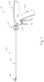
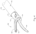
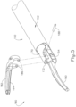
- FIGS. 8A-9 show an alternative shaft assembly (250) and alternative end effector (280) that may be readily incorporated into instrument (10) described above in place of shaft assembly (150) end effector (180).
- End effector (280) includes a clamp arm (282) and a clamp pad (284) that are substantially similar to clamp arm (182) and clamp pad (184) described above, with differences described in detail below.
- shaft assembly (250) includes an outer tube (252), an inner tube (270), and an acoustic waveguide (292) extending through both outer tube (252) and inner tube (270).
- Outer tube (252), inner tube (270), and acoustic waveguide (292) are substantially similar to outer tube (152), inner tube (170), and acoustic waveguide (192) mentioned above, respectively, with differences described below.
- outer tube (252) is operable to translate longitudinally relative to inner tube (270) to selectively pivot clamp arm (282) toward and away from blade (290).
- integral pin features (286) of clamp arm (282 which are substantially similar to integral pin features (186) mentioned above, pivotally secure a first portion of clamp arm (282) to pin slot (256) of a distally projecting tongue (254) of outer tube (252); while integral pin features (288) pivotally secure a second portion of clamp arm (282) to angled distal prongs (272) of inner tube (270) via pin holes (276). It should be understood that integral pin features (286) may vertically translate within pin slot (256).
- tubes (252, 270) cooperate to pivot clamp arm (282) toward blade (290) when outer tube (252) is retracted proximally relative to inner tube (270).
- clamp arm (282) may be pivoted back away from blade (290) (e.g., from the position shown in FIG. 8B to the position shown in FIG 8A ) by translating outer tube (252) distally relative to inner tube (270), in reverse of the operation shown in FIGS. 8A-8B .
- clamp arm (282) may be pivoted toward blade (290) to grasp, compress, seal, and sever tissue captured between clamp pad (282) and blade (290).
- Clamp arm (282) may be pivoted away from blade (290) to release tissue from between clamp pad (282) and blade (290); and/or to perform blunt dissection of tissue engaging opposing outer surface of clamp arm (282) and blade (290).
- inner tube (170) includes distally projecting tongue (172)
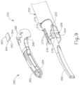
- inner tube (270) of the present example includes a pair of angled distal prongs (272) defining a longitudinal channel (274).
- Angled distal prongs (272) each have a flat surface (278) extending from prongs (272). Together, each angled distal prong (272) and corresponding flat surface (278) define a pin hole (276).
- pin holes (276) are dimensioned to receive integral pins (288) of clamp arm (282).
- end effector (280) further includes a cap (260).
- Cap (260) includes a spacer (262) and a pair of flanges (264).
- Spacer (262) is dimensioned with fit within longitudinal channel (274) while flanges (264) are dimensioned to rest on top of angled distal prongs (272).
- cap (260) is configured to fix integral pins (288) within pin holes (276) once clamp arm (282) is assembled to inner tube (270).
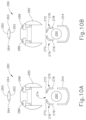
- FIGS. 10A-10E show an exemplary assembly of clamp arm (282) and inner tube (270).
- clamp arm (282) is placed over angled distal prongs (272) such that integral pins (288) are laterally aligned with angled distal prongs (272).
- inner tube (270) is made out of a resilient material, such that angled distal prongs (272) may flex relative to one another within longitudinal channel (274). Therefore, as seen in FIG. 10B , a user may pinch angled distal prongs (272) or flats (278) together, such that angled distal prongs (272) flex toward each other within longitudinal channel (274). Integral pins (288) and angled distal prongs (272) are then no longer laterally aligned, but both angled distal prongs (272) are laterally between integral pins (288).
- cap (260) With integral pins (288) located in pin holes (276), and as shown in FIG. 10E , cap (260) is then placed on top of inner tube (270) such that spacer (262) lies within longitudinal channel (274) while abutting against both angled distal prongs (272). Additionally, flanges (264) rest on top angled distal prongs (272). With cap (260) in place, angled distal prongs (272) and/or flats (278) are no longer capable of deflecting inwardly toward one another within longitudinal channel (274) to release integral pins (288) from pin holes (276).
- cap (260) may be welded to angled distal prongs (272) to fix cap (260) to inner tube (270), and therefore fix clamp arm (282) to inner tube (270).
- any other suitable method of fixing cap (260) to angled distal prongs (272) may be used as would be apparent to one having ordinary skill in the art in view of the teachings herein.
- integral pins (288) do not extend laterally across the width of inner tube (270). Additionally, integral pins (288) are dimensioned to not extend across the lateral width of blade (290). Therefore, the chances of blade (290) making contact with integral pins (288) are reduced or eliminated.
- FIGS. 11A-11B show another alternative shaft assembly (350) and alternative end effector (380) that may be readily incorporated into instrument (10) described above in place of shaft assembly (150) end effector (180).
- End effector (380) includes a clamp arm (382) and clamp pad (384) that are substantially similar to clamp arm (182) and clamp pad (184) described above, with difference described in detail below.
- Shaft assembly (350) includes an outer tube (352), an inner tube (370), and an acoustic waveguide (392) extending through both outer tube (352) and inner tube (370).
- Outer tube (252), inner tube (270), and acoustic waveguide (292) are substantially similar to outer tube (152), inner tube (170), and acoustic waveguide (192) mentioned above, respectively, with differences described below.
- outer tube (352) is operable to translate longitudinally relative to inner tube (370) to selectively pivot clamp arm (382) toward and away from blade (390).
- integral pin features (386) of clamp arm (382) which are substantially similar to integral pin features (186) mentioned above, pivotally secure a first portion of clamp arm (382) to pin slot (356) of a distally projecting tongue (354) of outer tube (352); while integral pin features (388) pivotally secure a second portion of clamp arm (382) to angled distal prongs (372) of inner tube (370) via pin holes (376). It should be understood that integral pin features (386) may vertically translate within pin slot (356).
- tubes (352, 370) cooperate to pivot clamp arm (382) toward blade (390) when outer tube (352) is retracted proximally relative to inner tube (370).
- clamp arm (382) may be pivoted back away from blade (390) (e.g., from the position shown in FIG. 11B to the position shown in FIG 11A ) by translating outer tube (352) distally relative to inner tube (370), in reverse of the operation shown in FIGS. 11A-11B .
- clamp arm (382) may be pivoted toward blade (390) to grasp, compress, seal, and sever tissue captured between clamp pad (382) and blade (390).
- Clamp arm (382) may be pivoted away from blade (390) to release tissue from between clamp pad (382) and blade (390); and/or to perform blunt dissection of tissue engaging opposing outer surface of clamp arm (382) and blade (390).
- inner tube (170) includes distally projecting tongue (172)
- inner tube (370) of the present example includes a pair of angled distal prongs (372) defining a longitudinal channel (374).
- Angled distal prongs (372) each have a flat surface (378) extending from prongs (372). Together, each angled distal prong (372) and corresponding flat surface (378) define a pin hole (376).
- pin holes (376) are dimensioned to receive integral pins (388) of clamp arm (382).
- a tab (360) is integrally fixed on one angled distal prong (372), and extends across longitudinal channel (375) above the other angled distal prong (372).
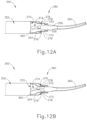
- FIGS. 12A-12E show an exemplary assembly of clamp arm (382) and inner tube (370).
- FIG. 12A shows shaft assembly (350) and end effector (380) without clamp arm (382) attached. Similar to clamp arm (282) in FIG. 10A , clamp arm (382) may be placed over angled distal prongs (372) such that integral pins (388) are laterally aligned with angled distal prongs (372).
- inner tube (370) is made out of a resilient material, such that angled distal prongs (372) may flex relative to one another within longitudinal channel (374). Therefore, as seen in FIG.
- an operator may pinch angled distal prongs (372) or flats (378) together, such that angled distal prongs (372) flex toward each other within longitudinal channel (374).
- angled distal prongs (372) are then spaced such that integral pins (388) may slide within pin holes (376) and abut against the portion of pin holes (376) defined by flats (378). At this stage, integral pins (388) are within pin holes (376).
- integral pins (388) are within pin holes (376), and as seen in FIG. 12D , the operator may now release angled distal prongs (372) and/or flats (378). Due to the resilient nature of angled distal prongs (372) and flats (378), both angled distal prongs (372) and flats (378) return to their natural position, as shown in FIG. 12D . Additionally, integral pins (388) abut against both angled distal prongs (372) and flats (378). Integral pins (388) are now fixed within pin holes (376) at this stage. With pins (388) fixed within pin holes (376), and as shown in FIG.
- the operator may fix or secure tab (360) to the other angled distal prong (372) that tab (360) is not already integrally fixed to.
- End (362) of tab (360) may be fixed to the other angled distal prong (372) through welding or any other suitable method known to one having ordinary skill in the art in view of the teachings herein.
- tab (360) fixed to both angled distal prongs (372) angled distal prongs (372) and/or flats (378) are no longer capable of deflecting inwardly toward one another to release integral pins (388) from pin holes (376).
- integral pins (388) do not extend laterally across the width of inner tube (370). Additionally, integral pins (388) are dimensioned to not extend across the lateral width of blade (390). Therefore, chances of blade (390) making contact with integral pins (388) are reduced or eliminated.
- integral pins (388) may have angled surfaces that cooperate with angled distal prongs (372) to further promote this camming action.
- FIGS. 13A-14C show another alternative shaft assembly (450) and alternative end effector (480) that may be readily incorporated into instrument (10) described above in place of shaft assembly (150) end effector (180).
- End effector (480) includes a clamp arm (482) and clamp pad (484) that are substantially similar to clamp arm (282) and clamp pad (284) described above, with difference described in detail below.
- shaft assembly (450) includes an outer tube (452), an inner tube (470), and an acoustic waveguide (492) extending through both outer tube (452) and inner tube (470).
- Outer tube (452), inner tube (470), and acoustic waveguide (492) are substantially similar to outer tube (252), inner tube (270), and acoustic waveguide (292) mentioned above, respectively, with differences described below.
- outer tube (452) is operable to translate longitudinally relative to inner tube (470) to selectively pivot clamp arm (482) toward and away from blade (490).
- integral pin features (486) of clamp arm (482) which are substantially similar to integral pin features (286) mentioned above, pivotally secure a first portion of clamp arm (482) to pin slot (456) of a distally projecting tongue (454) of outer tube (452); while integral pin features (488) pivotally secure a second portion of clamp arm (482) to angled distal prongs (472) of inner tube (470) via pin holes (476). It should be understood that integral pin features (486) may vertically translate within pin slot (456).
- tubes (452, 470) cooperate to pivot clamp arm (482) toward blade (490) when outer tube (452) is retracted proximally relative to inner tube (470).
- clamp arm (482) may be pivoted back away from blade (490) (e.g., from the position shown in FIG. 13B to the position shown in FIG 13A ) by translating outer tube (452) distally relative to inner tube (470), in reverse of the operation shown in FIGS. 13A-13B .
- clamp arm (482) may be pivoted toward blade (490) to grasp, compress, seal, and sever tissue captured between clamp pad (482) and blade (490).
- Clamp arm (482) may be pivoted away from blade (490) to release tissue from between clamp pad (482) and blade (490); and/or to perform blunt dissection of tissue engaging opposing outer surface of clamp arm (482) and blade (490).
- inner tube (470) of the present example includes a pair of angled distal prongs (472) defining a longitudinal channel (474). Angled distal prongs (472) each have a flat surface (478) extending from prongs (472). Together, each angled distal prong (472) and corresponding flat surface (478) define a pin hole (476).
- Clamp arm (482) may be attached to inner tube (470) in substantially the same manner as described above for coupling clamp arm (282) with inner tube (270), with the difference of inserting removable cap (460) as will be describe below.
- inner tube (470) is made out of a resilient material, such that angled distal prongs (472) may flex relative to one another within longitudinal channel (474).
- Pin holes (476) are dimensioned to receive integral pins (488) of clamp arm (482) when angled distal prongs (472) and flats (478) are flexed toward each other within longitudinal channel (474). With integral pins (488) inserted into pin holes (476), angled distal prongs (472) and flats (478) may return to their natural position such that integral pins (488) abut against portions of angled distal prongs (472) and flats (478) defining pin holes (476).
- removable cap (460) When pins (488) are disposed in corresponding pin holes (476), and as best seen in FIGS. 14A-14C , removable cap (460) may be inserted into longitudinal channel (474) to prevent angled distal prongs (472) and/or flats (478) from deflecting inwardly toward one another to release integral pins (488) from pin holes (476).
- Removable cap (460) includes a spacer portion (462), a resilient portion (464) extending from spacer portion (462), and a tab (466) extending from resilient portion (4-64).
- longitudinal channel (474) includes an access channel (473) and a locking channel (475).
- Access channel (473) is sized so an operator may insert an object or their finger within access channel (473) to selectively remove removable cap (460) by sliding removable cap (460) distally.
- Locking channel (475) is sized to receive tab (466) when removable cap (460) is fully inserted, thereby longitudinally locking removable cap (460) relative to inner tube (470).
- Spacer portion (462) defines a pair of longitudinal slots (468).
- Longitudinal slots (468) are sized to receive the inner edges of angled distal prongs (472) when removable cap (460) is installed.
- the operator may vertically align longitudinal slots (468) with the edges of angled distal prongs (472) so that longitudinal slots (468) house the edges of angled distal prongs (472).
- Resilient member is capable of bending, such that tab (466) may vertically move relative to spacer portion (462).
- tab (466) may slide on top of longitudinal channel (474) and angled distal prongs (472).
- tab (466) may fit within locking channel (475). With tab (466) no longer forced above longitudinal channel (464) through engagement with angled distal prongs (472), the resilient nature of resilient portion (464) moves tab (466) within locking channel (475). Tab (466) is thereby vertically aligned with spacer portion (462) at this stage. As described above, spacer portion (462) is located between angled distal prongs (472) such that angled distal prongs (472) and/or flats (478) are no longer capable of deflecting inwardly toward one another to release integral pins (488) from pin holes (476).
- tab (466) resting within locking channel (475) prevents unintentional longitudinal movement of removable cap (460) relative to inner tube (470). If an operator desires to remove removable cap (460) (e.g. to remove clamp arm (482)), the operator may push tab (466) downwardly so tab (466) no longer engages locking channel (475), then slide removable cap (460) in the distal direction. Alternatively, an operator user may insert an object or their finger into access channel (473) in order to lift tab (466) above locking channel (475), then slide removable cap (460) in the distal direction.
- ultrasonic blade (190, 290, 390, 490) and waveguide (192, 292, 393, 492) are oriented in the same angular position relative to shaft assembly (150, 250, 350, 450) and end effector (180, 280, 380, 480) every time a user reassembles ultrasonic blade (190, 290, 390, 490) and waveguide (192, 292, 392, 492) within end effector (180, 280, 380, 480) and shaft assembly (150, 250, 350, 450).
- ultrasonic blade Having consistency in the angular orientation of ultrasonic blade (190, 290, 390, 490) and waveguide (192, 292, 393, 492) may also be particularly desirable in contexts where ultrasonic blade (190, 290, 390, 490) extends along a curve, to ensure that the curve of a complimentarily curved clamp arm (182, 282, 382, 482) is aligned with the curve of ultrasonic blade (190, 290, 390, 490).
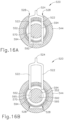
- FIGS. 15A-15B show an alternative shaft assembly (550) and an alternative body portion (510) that may be readily incorporated into instrument (10) described above.
- Shaft assembly (550) includes a rotation assembly (540) that is operable to rotate shaft assembly (550) relative to body portion (510).
- Rotation assembly (540) includes a rotation knob (542) unitarily attached to a sleeve (544) extending into body portion (510).
- Shaft assembly further includes an outer tube (552), an inner tube (570), and a waveguide (592) extending through inner tube (570) and outer tube (552).
- Outer tube (552), inner tube (570) and waveguide (592) are substantially similar to outer tube (152), inner tube (170), and waveguide (192) described above, respectively, with differences described below.
- a portion of outer tube (552), inner tube (570) and waveguide (592) extend through rotation knob (542) and sleeve (544).
- Body portion (510) also houses a spring loaded key lock assembly (520).
- spring loaded key lock assembly (520) is capable of selectively locking the longitudinal position of waveguide (592) relative to inner tube (570). Additionally, as will be described in greater detail below, spring loaded key lock assembly (520) is also capable of unlocking waveguide (592) relative to inner tube (570) and outer tube (552), such that waveguide (592) may be removed from body portion (510) for cleaning or other reasons.
- Spring loaded key lock (520) includes a handle (524) that is connected to a pair of locking forks (522).
- Lock (520) further includes a biasing member (526) that is fixed to sleeve (544) of rotation assembly (540) and handle (524).
- Locking forks (522) extend from handle (524) toward sleeve (544).
- biasing member (526) biases handle (524) toward sleeve (544).
- an operator may pull handle (524) away from sleeve (544) to stretch biasing member (526).
- biasing member (526) will resiliently actuate handle (525) toward sleeve (544).
- sleeve (544), outer tube (552), and inner tube (570) define a pair of key slots (528) that are dimensioned to receive locking forks (522). Locking forks (522) may also actuate within key slots (528).
- waveguide (592) defines a pair of keyed flats (594) and a pair of faces (595). Faces (595) are adjacent and perpendicular to keyed flats (594).
- keyed flats (594) are dimensioned with a substantially similar, if not exact, width of locking forks (522).
- an operator may pull handle (524) away from sleeve (544) so that locking forks (522) travel along key slots (528). Locking forks (522) may travel along key slots (528) until locking forks (522) no longer make contact with faces (595) or keyed flats (594). An operator may thus pull waveguide (592) in the proximal direction until waveguide (592) is sufficiently removed from inner tube (570) and outer tube (552).
- the operator may pull handle (524) away from sleeve (544), insert waveguide (592) into inner tube (570) and outer tube (552) until locking forks (522) align with keyed flats (594), and then allow biasing member (526) to force locking forks (522) within key slots (528).
- FIGS. 17-18C show another alternative shaft assembly (650) that may be readily incorporated into instrument (10) described above.
- Shaft assembly (650) includes an ultrasonic waveguide (692), an inner tube (670), an outer tube (652), and a rotation assembly (640); which are substantially similar to ultrasonic waveguide (192), inner tube (170), outer tube (152), and rotation assembly (540), respectively, except for the differences described below.
- ultrasonic waveguide (692) includes a seal (696), a cam pin (694) and a threaded stud (698) that is configured to couple with an ultrasonic transducer (not shown).
- Inner tube (670) includes a cam slot (672) extending from the proximal end of inner tube (670) and terminating at a placement hole (674).
- Outer tube (652) includes a cam slot (654) extending from the proximal end of outer tube (652) and terminating in a translation slot (656).
- Rotation assembly (640) includes a rotation knob (642) defining a channel (646) and a locking feature (644). Locking feature (644) may actuate relative to the rest of rotation assembly (640). It should be understood that cam pin (694) may fit within both cam slots (672, 654) and radially extend from the rest of ultrasonic waveguide (692) as to extend beyond the dimensions of inner tube (670) and outer tube (652).
- FIGS. 18A-18C show how waveguide (692) may be assembled within outer tube (652), inner tube (670), and rotation knob (642). Outer tube (652) and inner tube (670) are partially disposed within channel (646) of rotation knob (642). An operator may insert the distal end of waveguide (692) into the proximal openings of inner tube (670) and outer tube (552) such that cam pin (694) is aligned with cam slots (672, 654). As mentioned above, camp pin (694) extends radially outwardly from the rest of ultrasonic waveguide (692) such that cam pin (694) extends beyond the dimensions of inner tube (670) and outer tube (652).
- cam pin (694) when cam pin (694) is aligned with cam slots (672, 654), cam pin (694) extends through inner tube (670) and outer tube (652) via cam slots (672, 654). It should be understood that cam slots (672, 654) are aligned when outer tube (652) is actuated to its most distal position relative to inner tube (670). However, cam slots (672, 654) may be dimensioned to align at any other longitudinal location of outer tube (652) relative to inner tube (670) as would be apparent to one having ordinary skill in the art in view of the teachings herein.
- waveguide (692) As shown in FIG. 18B , the operator push ultrasonic waveguide (692) in the distal direction. As waveguide (692) travels distally, cam slots (672, 654) force waveguide (692) to rotate via cam pin (694). Waveguide (692) may travel distally within inner tube (670) and outer tube (652) until cam pin (694) reaches placement hole (674) as shown in FIG. 18B . Because cam pin (694) is located at the same location relative to the rest of waveguide (692), and because cam slots (672, 654) are located at the same location when aligned, waveguide (692) will uniformly locate in the same longitudinal and rotational position every time waveguide (692) is inserted into inner tube (670) and outer tube (652).
- Placement hole (674) is located directly adjacent to locking feature (644). As described above, locking feature (644) is capable of actuating relative to the rest of rotation assembly (640). Additionally, locking feature (644) is dimensioned for a snap fit with cam pin (694) when locking feature (644) is actuated toward cam pin (694) as shown in FIG. 18C . Waveguide (692) is thereby rotationally and longitudinally fixed relative to rotation assembly (640). While locking feature (644) uses a snap fit to lock with cam pin (694) in the current example, any other suitable method of fixing cam pin (694) to locking feature (644) may be utilized as would be apparent to one having ordinary skill in the art in view of the teachings herein.
- waveguide (692) may be removed for cleaning or other purposes. If an operator wishes to remove waveguide (692) for cleaning or other purposes, the operator may actuate locking feature (644) in the upward direction so that locking feature (644) is no longer fixed to cam pin (694). The operator may then pull waveguide (692) in the proximal direction to further remove waveguide (692) from inner tube (670) and outer tube (652)
- translation slot (656) of outer tube (652) is dimensioned to allow outer tube (652) to longitudinally travel relative to inner tube (670) such that outer tube (652) does not interfere with cam pin (694) when waveguide (692) is assembled in place and secured by locking feature (644). Therefore, the operator may still open and close a clamp arm relative to a blade.
- cam pin (694) and one pair of cam slots (672, 654) are utilized in the current example, any suitable number of cam pins (694) and cam slots (672, 654) may be utilized.
- FIG. 19 shows an ultrasonic blade (792) and body portion (710) that may be readily incorporated into instrument (10) described above.
- body portion (710) includes a shroud (712) defining a pair of rotating recesses (714).
- rotating recesses (714) of shroud (712) are configured to rotationally and longitudinally align ultrasonic blade (792) relative to the rest of body portion (710).
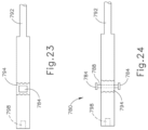
- waveguide (792) includes a threaded recess (798) that is configured to couple waveguide (792) with an ultrasonic transducer (not shown), a silicone portion (794) defining a pin hole (796), and a clocking pin (780) that is configured to fit within pin hole (796) of silicone portion (794).
- Clocking pin (780) includes a pin (786) surrounded by a silicone overmold (788).
- Clocking pin (780) further includes a pair of clocking blocks (784) located at the ends of pin (786).
- Clocking blocks (784) may be made out of a plastic material or contain a plastic overmold.
- Silicone portion (794) and silicone overmold (788) help isolate ultrasonic waveguide (792) from clocking pin (780). This may help prevent clocking pin (780) from transmitting acoustic vibrations that are transmitted through waveguide (792) to an ultrasonic blade.
- Clocking pin (780) fits within pin hole (796) in such a way that clocking pin (780) is fixed relative to ultrasonic waveguide (792).
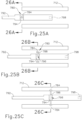
- FIGS. 25A-26C show an exemplary assembly of waveguide (792).
- the proximal end of ultrasonic waveguide (792) is inserted into the distal end of shroud (712).
- Clocking blocks (784) of clocking pin (780) are thereby inserted into the origin of rotating recesses (714).
- Rotating recesses (714) define respective helical paths within shroud (712). Therefore, as shown in FIG. 25B and FIG. 26B , as waveguide (792) is rotated, clocking blocks (784), and therefore waveguide (792), travel proximally within shroud (712) while rotating to a predetermined angular orientation.
- clocking blocks (784) reach the termination of rotating recesses (714). At this point, waveguide (792) cannot further rotate or travel proximally relative to shroud (712). Because shroud (712) is fixed relative to the rest of body (710), waveguide (792) will be uniformly placed in the same longitudinal and angular position every time waveguide (792) is "clocked" within shroud (712). An operator may remove waveguide (792) for cleaning and reinsert waveguide (792) back into shroud (712) at the exact location for subsequent use.
- waveguide (792) may also be configured to be inserted in the proximal end of shroud (712).
- FIGS. 27A-27B show an alternative body (810), shaft assembly (850), and end effector (880) that may be readily incorporated into instrument (10) described above.
- Shaft assembly (850) and end effector (880) are substantially similar to shaft assembly (150) and end effector (180) described above, with differences described below.
- Shaft assembly (850) includes an outer tube (852), an inner tube (not shown), a waveguide (892) and a rotation assembly (840); which are substantially similar to outer tube (152), inner tube (170), waveguide (192) and rotation assembly (540) described above.
- Rotation assembly (840) includes a rotation knob (842) substantially similar to rotation knob (542) described above.
- Waveguide (892) defines a pin hole (891) that is configured to be used in coupling waveguide (892) to body (810).
- End effector (880) includes a clamp arm (882) and an acoustic blade (890) substantially similar to clamp arm (182) and acoustic blade (190) mentioned above.
- Body (810) includes a trigger (820), a tether (894) connected to waveguide (892) at a connection point (898), and a tether housing (812) that stores a coiled portion (896) of tether (894).
- Tether (894) extends from coiled portion (896) in such a way that portions of tether (894) may extend out of coiled portion (896), as shown in FIG. 27B .
- Coiled portion (896) may have recoil function, such that tugging on the portion of tether (894) extending from coiled portion (896) encourages coiled portion (896) to recoil excess lengths of tether (894). As shown in FIG.
- connection point (898) couples tether (894) with waveguide (892) such that waveguide (892) can be removed relative to the rest of shaft assembly (850), but cannot be removed entirely relative to body (810). In other words, even if waveguide (892) is removed from shaft assembly (850) for cleaning, waveguide (892) cannot be completely detached from body (810) due to tether (894).
- Connection point (898) may consist of a groove on waveguide (892) in which tether (894) is tied around.
- connection point (898) may comprise an overmold of silicone on the portion of tether (894) in contact with waveguide (892).
- tether (894) may be secured to waveguide (892) will be apparent to one having ordinary skill in the art in view of the teachings herein.
- An apparatus comprising: (a) a shaft assembly defining a longitudinal axis, wherein the shaft assembly comprises: (i) a first coupling member, and (ii) a second coupling member, wherein the first coupling member and the second coupling member are configured to flex toward each other from a first position to a second position, wherein the first coupling member and the second coupling member define a pivot axis in the first position; and (b) an end effector comprising: (i) an ultrasonic blade extending from the shaft assembly, (ii) a lamp arm configured to couple or decouple with the shaft assembly when the first coupling member and the second coupling member are in the second position, wherein the clamp arm is configured to pivot toward and away the ultrasonic blade about the pivot axis when the first coupling member and the second coupling member are in the first position.
- the clamp arm comprises a first integral pin and a second integral pin, wherein the first integral pin is configured to couple or decouple with the first coupling member when the first coupling member and the second coupling member are in the second position, wherein the second integral pin is configured to couple or decouple with the second coupling member when the first coupling member and the second coupling member are in the second position.
- Example 2 wherein the first integral pin and the second integral pin define a lateral gap, wherein the width of the ultrasonic blade is smaller than the lateral gap.
- first coupling member and the second coupling member define a longitudinal channel, wherein the longitudinal channel is wider in the first position than the second position.
- Example 4 wherein the first coupling member comprises a tab, wherein the tab extends over the longitudinal channel toward the second coupling member.
- Example 5 The apparatus of Example 5, wherein the tab is configured to be fixed to the second coupling member, wherein the tab is configured to prevent the first coupling member and the second coupling member from flexing to the second position when the tab is fixed to the second coupling member.
- Example 7 The apparatus of Example 7, wherein the cap comprises a spacer, wherein the spacer is dimensioned to fit within the longitudinal channel when the first coupling member and the second coupling member are in the first position.
- Example 8 wherein the spacer is configured to prevent the first coupling member and the second coupling member from flexing from the first position to the second position when the spacer is within the longitudinal channel.
- Example 9 wherein the cap comprises a first flange and a second flange, wherein the first flange is configured to rest on top of the first coupling member, wherein the second flange is configured to rest on top of the second coupling member.
- Example 10 The apparatus of Example 10, wherein the first flange is configured to fix to the first coupling member, wherein the second flange is configured to fix to the second coupling member.
- the spacer defines a first longitudinal slot and a second longitudinal slot, wherein the first longitudinal slot is configured to house a portion of the first coupling member, wherein the second longitudinal slot is configured to house a portion of the second coupling member.
- the cap further comprises a tab, wherein the first coupling member and the second coupling member further define a locking channel, wherein the tab is dimensioned to fit within the locking channel, wherein the tab is configured to prevent longitudinal movement of the cap when the tab is within the locking channel.
- Example 13 The apparatus of Example 13, wherein the cap further comprises a resilient member positioned between the tab and the spacer.
- An apparatus comprising: (a) an end effector comprising an ultrasonic blade; and (b) a shaft assembly defining a longitudinal axis, wherein the ultrasonic blade extends from the shaft assembly, wherein the shaft assembly comprises: (i) a first tube, (ii) an acoustic waveguide extending through the first tube, wherein the acoustic waveguide is unitarily attached to the ultrasonic blade, wherein the acoustic waveguide is configured to be removed from the first tube, and (iii) a locating feature, wherein the locating feature is configured to orient the acoustic waveguide relative to the first tube along the longitudinal axis and about the longitudinal axis.
- Example 15 wherein the locating feature comprises a key lock, wherein the acoustic waveguide defines a recess configured to mate with the key lock to orient the acoustic waveguide relative to the first tube.
- Example 16 wherein the key lock is biased to engage the recess defined by the acoustic waveguide.
- the locating feature comprises a cam slot defined by the first tube, wherein the acoustic waveguide comprises a cam pin configured to be inserted into the cam slot.
- Example 18 The apparatus of Example 18, wherein the shaft assembly further comprises a locking feature configured to selectively fix to the cam pin.
- An apparatus comprising: (a) a body portion; (b) a shaft assembly extending distally from the body portion, wherein the shaft assembly comprises: (i) an acoustic waveguide, and (ii) a tube, wherein the acoustic waveguide is configured to fit coaxially within the tube, wherein the acoustic waveguide is configured to be removed from the tube; and (c) a tether, wherein a first end of the tether is coupled with the body portion, wherein a second portion of the tether is coupled with the acoustic waveguide, wherein the tether has a length configured to enable removal of the acoustic waveguide from the tube while still coupling the acoustic waveguide with the body portion.
- any of the versions of instruments described herein may include various other features in addition to or in lieu of those described above.
- any of the instruments described herein may also include one or more of the various features disclosed in any of the various references that are incorporated by reference herein.
- teachings herein may be readily applied to any of the instruments described in any of the other references cited herein, such that the teachings herein may be readily combined with the teachings of any of the references cited herein in numerous ways.
- Other types of instruments into which the teachings herein may be incorporated will be apparent to those of ordinary skill in the art.
- any ranges of values referred to herein should be read to include the upper and lower boundaries of such ranges. For instance, a range expressed as ranging "between approximately 1.0 inches and approximately 1.5 inches” should be read to include approximately 1.0 inches and approximately 1.5 inches, in addition to including the values between those upper and lower boundaries.
- Versions of the devices described above may have application in conventional medical treatments and procedures conducted by a medical professional, as well as application in robotic-assisted medical treatments and procedures.
- various teachings herein may be readily incorporated into a robotic surgical system such as the DAVINCI TM system by Intuitive Surgical, Inc., of Sunnyvale, California.
- DAVINCI TM system by Intuitive Surgical, Inc., of Sunnyvale, California.
- teachings herein may be readily combined with various teachings of U.S. Pat. No. 6,783,524, entitled "Robotic Surgical Tool with Ultrasound Cauterizing and Cutting Instrument," published August 31, 2004 , the disclosure of which is incorporated by reference herein.
- Versions described above may be designed to be disposed of after a single use, or they can be designed to be used multiple times. Versions may, in either or both cases, be reconditioned for reuse after at least one use. Reconditioning may include any combination of the steps of disassembly of the device, followed by cleaning or replacement of particular pieces, and subsequent reassembly. In particular, some versions of the device may be disassembled, and any number of the particular pieces or parts of the device may be selectively replaced or removed in any combination. Upon cleaning and/or replacement of particular parts, some versions of the device may be reassembled for subsequent use either at a reconditioning facility, or by an operator immediately prior to a procedure.
- reconditioning of a device may utilize a variety of techniques for disassembly, cleaning/replacement, and reassembly. Use of such techniques, and the resulting reconditioned device, are all within the scope of the present application.
- versions described herein may be sterilized before and/or after a procedure.
- the device is placed in a closed and sealed container, such as a plastic or TYVEK bag.
- the container and device may then be placed in a field of radiation that can penetrate the container, such as gamma radiation, x-rays, or high-energy electrons.
- the radiation may kill bacteria on the device and in the container.
- the sterilized device may then be stored in the sterile container for later use.
- a device may also be sterilized using any other technique known in the art, including but not limited to beta or gamma radiation, ethylene oxide, or steam.
Landscapes
- Health & Medical Sciences (AREA)
- Life Sciences & Earth Sciences (AREA)
- Engineering & Computer Science (AREA)
- Surgery (AREA)
- Public Health (AREA)
- Biomedical Technology (AREA)
- Animal Behavior & Ethology (AREA)
- General Health & Medical Sciences (AREA)
- Nuclear Medicine, Radiotherapy & Molecular Imaging (AREA)
- Veterinary Medicine (AREA)
- Mechanical Engineering (AREA)
- Dentistry (AREA)
- Heart & Thoracic Surgery (AREA)
- Medical Informatics (AREA)
- Molecular Biology (AREA)
- Radiology & Medical Imaging (AREA)
- Surgical Instruments (AREA)
- Manipulator (AREA)
Applications Claiming Priority (3)
| Application Number | Priority Date | Filing Date | Title |
|---|---|---|---|
| US14/976,127 US10231749B2 (en) | 2015-12-21 | 2015-12-21 | Ultrasonic surgical instrument with blade replacement features |
| PCT/US2016/066451 WO2017112467A2 (fr) | 2015-12-21 | 2016-12-14 | Instrument chirurgical ultrasonore présentant une fonction de remplacement de lame |
| EP16871767.6A EP3393380B1 (fr) | 2015-12-21 | 2016-12-14 | Instrument chirurgical ultrasonore présentant une fonction de remplacement de lame |
Related Parent Applications (1)
| Application Number | Title | Priority Date | Filing Date |
|---|---|---|---|
| EP16871767.6A Division EP3393380B1 (fr) | 2015-12-21 | 2016-12-14 | Instrument chirurgical ultrasonore présentant une fonction de remplacement de lame |
Publications (2)
| Publication Number | Publication Date |
|---|---|
| EP4545022A2 true EP4545022A2 (fr) | 2025-04-30 |
| EP4545022A3 EP4545022A3 (fr) | 2025-07-02 |
Family
ID=58995216
Family Applications (2)
| Application Number | Title | Priority Date | Filing Date |
|---|---|---|---|
| EP16871767.6A Active EP3393380B1 (fr) | 2015-12-21 | 2016-12-14 | Instrument chirurgical ultrasonore présentant une fonction de remplacement de lame |
| EP25151871.8A Pending EP4545022A3 (fr) | 2015-12-21 | 2016-12-14 | Instrument chirurgical à ultrasons avec éléments de remplacement de lame |
Family Applications Before (1)
| Application Number | Title | Priority Date | Filing Date |
|---|---|---|---|
| EP16871767.6A Active EP3393380B1 (fr) | 2015-12-21 | 2016-12-14 | Instrument chirurgical ultrasonore présentant une fonction de remplacement de lame |
Country Status (7)
| Country | Link |
|---|---|
| US (3) | US10231749B2 (fr) |
| EP (2) | EP3393380B1 (fr) |
| JP (1) | JP6882324B2 (fr) |
| CN (1) | CN108601605B (fr) |
| BR (1) | BR112018012563B1 (fr) |
| MA (1) | MA44161A (fr) |
| WO (1) | WO2017112467A2 (fr) |
Families Citing this family (5)
| Publication number | Priority date | Publication date | Assignee | Title |
|---|---|---|---|---|
| US7854706B2 (en) * | 2007-12-27 | 2010-12-21 | Devicor Medical Products, Inc. | Clutch and valving system for tetherless biopsy device |
| US10231749B2 (en) | 2015-12-21 | 2019-03-19 | Ethicon Llc | Ultrasonic surgical instrument with blade replacement features |
| EP3955834A4 (fr) * | 2019-04-17 | 2023-01-18 | Covidien LP | Guide d'onde ultrasonore et lame pour instruments chirurgicaux ultrasonores et son procédé de fabrication |
| US11123095B2 (en) * | 2019-04-30 | 2021-09-21 | Cilag Gmbh International | Blade grounding mechanisms and alternative pin designs |
| US11478268B2 (en) * | 2019-08-16 | 2022-10-25 | Covidien Lp | Jaw members for surgical instruments and surgical instruments incorporating the same |
Citations (21)
| Publication number | Priority date | Publication date | Assignee | Title |
|---|---|---|---|---|
| US5322055A (en) | 1993-01-27 | 1994-06-21 | Ultracision, Inc. | Clamp coagulator/cutting system for ultrasonic surgical instruments |
| US5873873A (en) | 1997-10-10 | 1999-02-23 | Ethicon Endo-Surgery, Inc. | Ultrasonic clamp coagulator apparatus having improved clamp mechanism |
| US5980510A (en) | 1997-10-10 | 1999-11-09 | Ethicon Endo-Surgery, Inc. | Ultrasonic clamp coagulator apparatus having improved clamp arm pivot mount |
| US6283981B1 (en) | 1998-06-29 | 2001-09-04 | Ethicon Endo-Surgery | Method of balancing asymmetric ultrasonic surgical blades |
| US6309400B2 (en) | 1998-06-29 | 2001-10-30 | Ethicon Endo-Surgery, Inc. | Curved ultrasonic blade having a trapezoidal cross section |
| US6325811B1 (en) | 1999-10-05 | 2001-12-04 | Ethicon Endo-Surgery, Inc. | Blades with functional balance asymmetries for use with ultrasonic surgical instruments |
| US6423082B1 (en) | 2000-03-31 | 2002-07-23 | Ethicon Endo-Surgery, Inc. | Ultrasonic surgical blade with improved cutting and coagulation features |
| US6783524B2 (en) | 2001-04-19 | 2004-08-31 | Intuitive Surgical, Inc. | Robotic surgical tool with ultrasound cauterizing and cutting instrument |
| US20060079874A1 (en) | 2004-10-08 | 2006-04-13 | Faller Craig N | Tissue pad for use with an ultrasonic surgical instrument |
| US20070191713A1 (en) | 2005-10-14 | 2007-08-16 | Eichmann Stephen E | Ultrasonic device for cutting and coagulating |
| US20070282333A1 (en) | 2006-06-01 | 2007-12-06 | Fortson Reginald D | Ultrasonic waveguide and blade |
| US20080200940A1 (en) | 2007-01-16 | 2008-08-21 | Eichmann Stephen E | Ultrasonic device for cutting and coagulating |
| US20080234710A1 (en) | 2007-03-22 | 2008-09-25 | Neurohr Mark A | Ultrasonic surgical instruments |
| US20100069940A1 (en) | 2008-09-12 | 2010-03-18 | Miller Matthew C | Ultrasonic Device for Fingertip Control |
| US8057498B2 (en) | 2007-11-30 | 2011-11-15 | Ethicon Endo-Surgery, Inc. | Ultrasonic surgical instrument blades |
| US20120116265A1 (en) | 2010-11-05 | 2012-05-10 | Houser Kevin L | Surgical instrument with charging devices |
| US20120112687A1 (en) | 2010-11-05 | 2012-05-10 | Houser Kevin L | Recharge system for medical devices |
| US8461744B2 (en) | 2009-07-15 | 2013-06-11 | Ethicon Endo-Surgery, Inc. | Rotating transducer mount for ultrasonic surgical instruments |
| US20140005701A1 (en) | 2012-06-29 | 2014-01-02 | Ethicon Endo-Surgery, Inc. | Surgical instruments with articulating shafts |
| US8623027B2 (en) | 2007-10-05 | 2014-01-07 | Ethicon Endo-Surgery, Inc. | Ergonomic surgical instruments |
| US20140114334A1 (en) | 2012-10-22 | 2014-04-24 | Ethicon Endo-Surgery, Inc. | Flexible harmonic waveguides/blades for surgical instruments |
Family Cites Families (26)
| Publication number | Priority date | Publication date | Assignee | Title |
|---|---|---|---|---|
| US5944737A (en) * | 1997-10-10 | 1999-08-31 | Ethicon Endo-Surgery, Inc. | Ultrasonic clamp coagulator apparatus having improved waveguide support member |
| US5935144A (en) * | 1998-04-09 | 1999-08-10 | Ethicon Endo-Surgery, Inc. | Double sealed acoustic isolation members for ultrasonic |
| US6254623B1 (en) | 1999-06-30 | 2001-07-03 | Ethicon Endo-Surgery, Inc. | Ultrasonic clamp coagulator surgical instrument with improved blade geometry |
| US6432118B1 (en) * | 1999-10-05 | 2002-08-13 | Ethicon Endo-Surgery, Inc. | Multifunctional curved blade for use with an ultrasonic surgical instrument |
| US6558376B2 (en) * | 2000-06-30 | 2003-05-06 | Gregory D. Bishop | Method of use of an ultrasonic clamp and coagulation apparatus with tissue support surface |
| JP2007048566A (ja) | 2005-08-09 | 2007-02-22 | Jst Mfg Co Ltd | 締結具及びこの締結具を用いたコネクタ |
| US20080147092A1 (en) * | 2006-10-23 | 2008-06-19 | Michael Rogge | Hybrid energy instrument combined with clip application capability |
| CN101820825A (zh) * | 2007-10-10 | 2010-09-01 | 伊西康内外科公司 | 用于切割和凝固的超声装置 |
| US9314261B2 (en) | 2007-12-03 | 2016-04-19 | Covidien Ag | Battery-powered hand-held ultrasonic surgical cautery cutting device |
| CN102413784B (zh) * | 2009-08-05 | 2014-07-16 | 奥林巴斯医疗株式会社 | 转矩扳手及超声波手术装置 |
| DE202010005727U1 (de) | 2010-04-22 | 2011-09-02 | Söring GmbH | Chirurgisches Instrument, insbesondere Ultraschallschere |
| US10881448B2 (en) * | 2010-11-05 | 2021-01-05 | Ethicon Llc | Cam driven coupling between ultrasonic transducer and waveguide in surgical instrument |
| US9782214B2 (en) | 2010-11-05 | 2017-10-10 | Ethicon Llc | Surgical instrument with sensor and powered control |
| CN103442658B (zh) * | 2010-11-05 | 2016-03-23 | 伊西康内外科公司 | 具有模块化夹持垫的外科器械 |
| US9375255B2 (en) * | 2010-11-05 | 2016-06-28 | Ethicon Endo-Surgery, Llc | Surgical instrument handpiece with resiliently biased coupling to modular shaft and end effector |
| US9039720B2 (en) * | 2010-11-05 | 2015-05-26 | Ethicon Endo-Surgery, Inc. | Surgical instrument with ratcheting rotatable shaft |
| US20130085419A1 (en) * | 2011-09-29 | 2013-04-04 | Tyco Healthcare Group Lp | Transducer/Waveguide Engagement Mechanisms for Ultrasonic Surgical Instruments |
| DE102011086326A1 (de) * | 2011-11-15 | 2013-05-16 | Söring GmbH | Ultraschallchirurgisches Instrument |
| US9364249B2 (en) | 2012-03-22 | 2016-06-14 | Ethicon Endo-Surgery, Llc | Method and apparatus for programming modular surgical instrument |
| US9351754B2 (en) * | 2012-06-29 | 2016-05-31 | Ethicon Endo-Surgery, Llc | Ultrasonic surgical instruments with distally positioned jaw assemblies |
| US20140330298A1 (en) | 2013-05-03 | 2014-11-06 | Ethicon Endo-Surgery, Inc. | Clamp arm features for ultrasonic surgical instrument |
| US9474887B2 (en) | 2013-09-24 | 2016-10-25 | Merit Medical Systems, Inc. | Surgical implement guide assembly and methods |
| US9743946B2 (en) | 2013-12-17 | 2017-08-29 | Ethicon Llc | Rotation features for ultrasonic surgical instrument |
| US10349967B2 (en) | 2014-02-28 | 2019-07-16 | Ethicon Llc | Ultrasonic surgical instrument with removable handle assembly |
| EP3282971B1 (fr) * | 2015-04-13 | 2020-05-06 | Ethicon LLC | Instrument chirurgical à ultrasons avec assemblage de poignée amovible |
| US10231749B2 (en) | 2015-12-21 | 2019-03-19 | Ethicon Llc | Ultrasonic surgical instrument with blade replacement features |
-
2015
- 2015-12-21 US US14/976,127 patent/US10231749B2/en active Active
-
2016
- 2016-12-14 JP JP2018550656A patent/JP6882324B2/ja active Active
- 2016-12-14 BR BR112018012563-6A patent/BR112018012563B1/pt active IP Right Grant
- 2016-12-14 EP EP16871767.6A patent/EP3393380B1/fr active Active
- 2016-12-14 MA MA044161A patent/MA44161A/fr unknown
- 2016-12-14 EP EP25151871.8A patent/EP4545022A3/fr active Pending
- 2016-12-14 WO PCT/US2016/066451 patent/WO2017112467A2/fr not_active Ceased
- 2016-12-14 CN CN201680074970.3A patent/CN108601605B/zh active Active
-
2018
- 2018-10-30 US US16/174,320 patent/US10973542B2/en active Active
-
2020
- 2020-12-21 US US17/128,523 patent/US11744607B2/en active Active
Patent Citations (24)
| Publication number | Priority date | Publication date | Assignee | Title |
|---|---|---|---|---|
| US5322055A (en) | 1993-01-27 | 1994-06-21 | Ultracision, Inc. | Clamp coagulator/cutting system for ultrasonic surgical instruments |
| US5322055B1 (en) | 1993-01-27 | 1997-10-14 | Ultracision Inc | Clamp coagulator/cutting system for ultrasonic surgical instruments |
| US5873873A (en) | 1997-10-10 | 1999-02-23 | Ethicon Endo-Surgery, Inc. | Ultrasonic clamp coagulator apparatus having improved clamp mechanism |
| US5980510A (en) | 1997-10-10 | 1999-11-09 | Ethicon Endo-Surgery, Inc. | Ultrasonic clamp coagulator apparatus having improved clamp arm pivot mount |
| US6283981B1 (en) | 1998-06-29 | 2001-09-04 | Ethicon Endo-Surgery | Method of balancing asymmetric ultrasonic surgical blades |
| US6309400B2 (en) | 1998-06-29 | 2001-10-30 | Ethicon Endo-Surgery, Inc. | Curved ultrasonic blade having a trapezoidal cross section |
| US6325811B1 (en) | 1999-10-05 | 2001-12-04 | Ethicon Endo-Surgery, Inc. | Blades with functional balance asymmetries for use with ultrasonic surgical instruments |
| US6773444B2 (en) | 1999-10-05 | 2004-08-10 | Ethicon Endo-Surgery, Inc. | Blades with functional balance asymmetries for use with ultrasonic surgical instruments |
| US6423082B1 (en) | 2000-03-31 | 2002-07-23 | Ethicon Endo-Surgery, Inc. | Ultrasonic surgical blade with improved cutting and coagulation features |
| US6783524B2 (en) | 2001-04-19 | 2004-08-31 | Intuitive Surgical, Inc. | Robotic surgical tool with ultrasound cauterizing and cutting instrument |
| US20060079874A1 (en) | 2004-10-08 | 2006-04-13 | Faller Craig N | Tissue pad for use with an ultrasonic surgical instrument |
| US20070191713A1 (en) | 2005-10-14 | 2007-08-16 | Eichmann Stephen E | Ultrasonic device for cutting and coagulating |
| US20070282333A1 (en) | 2006-06-01 | 2007-12-06 | Fortson Reginald D | Ultrasonic waveguide and blade |
| US20080200940A1 (en) | 2007-01-16 | 2008-08-21 | Eichmann Stephen E | Ultrasonic device for cutting and coagulating |
| US20080234710A1 (en) | 2007-03-22 | 2008-09-25 | Neurohr Mark A | Ultrasonic surgical instruments |
| US8623027B2 (en) | 2007-10-05 | 2014-01-07 | Ethicon Endo-Surgery, Inc. | Ergonomic surgical instruments |
| US8057498B2 (en) | 2007-11-30 | 2011-11-15 | Ethicon Endo-Surgery, Inc. | Ultrasonic surgical instrument blades |
| US8591536B2 (en) | 2007-11-30 | 2013-11-26 | Ethicon Endo-Surgery, Inc. | Ultrasonic surgical instrument blades |
| US20100069940A1 (en) | 2008-09-12 | 2010-03-18 | Miller Matthew C | Ultrasonic Device for Fingertip Control |
| US8461744B2 (en) | 2009-07-15 | 2013-06-11 | Ethicon Endo-Surgery, Inc. | Rotating transducer mount for ultrasonic surgical instruments |
| US20120116265A1 (en) | 2010-11-05 | 2012-05-10 | Houser Kevin L | Surgical instrument with charging devices |
| US20120112687A1 (en) | 2010-11-05 | 2012-05-10 | Houser Kevin L | Recharge system for medical devices |
| US20140005701A1 (en) | 2012-06-29 | 2014-01-02 | Ethicon Endo-Surgery, Inc. | Surgical instruments with articulating shafts |
| US20140114334A1 (en) | 2012-10-22 | 2014-04-24 | Ethicon Endo-Surgery, Inc. | Flexible harmonic waveguides/blades for surgical instruments |
Also Published As
| Publication number | Publication date |
|---|---|
| US10973542B2 (en) | 2021-04-13 |
| US11744607B2 (en) | 2023-09-05 |
| BR112018012563A2 (pt) | 2018-12-04 |
| JP6882324B2 (ja) | 2021-06-02 |
| EP3393380C0 (fr) | 2025-01-15 |
| WO2017112467A3 (fr) | 2017-11-02 |
| US20190125395A1 (en) | 2019-05-02 |
| US20170172615A1 (en) | 2017-06-22 |
| EP3393380B1 (fr) | 2025-01-15 |
| MA44161A (fr) | 2021-04-28 |
| CN108601605A (zh) | 2018-09-28 |
| JP2019502509A (ja) | 2019-01-31 |
| EP4545022A3 (fr) | 2025-07-02 |
| US20210137553A1 (en) | 2021-05-13 |
| EP3393380A2 (fr) | 2018-10-31 |
| CN108601605B (zh) | 2021-07-13 |
| BR112018012563B1 (pt) | 2022-08-02 |
| US10231749B2 (en) | 2019-03-19 |
| WO2017112467A2 (fr) | 2017-06-29 |
Similar Documents
| Publication | Publication Date | Title |
|---|---|---|
| US12004768B2 (en) | Methods and features for coupling ultrasonic surgical instrument components together | |
| US11666353B2 (en) | Surgical instrument with removable portion to facilitate cleaning | |
| US11744607B2 (en) | Ultrasonic surgical instrument with blade replacement features | |
| US9247986B2 (en) | Surgical instrument with ultrasonic transducer having integral switches | |
| BR112018007724B1 (pt) | Instrumento cirúrgico | |
| EP3554398A1 (fr) | Instrument chirurgical à ultrasons à joint coulissant de transducteur | |
| EP3068320A1 (fr) | Boîtier de batterie amovible pour instrument chirurgical | |
| WO2018111563A1 (fr) | Instrument chirurgical à ultrasons à joint coulissant de transducteur | |
| US11439427B2 (en) | Ultrasonic surgical instrument with clamp arm deflection feature | |
| EP3871618A1 (fr) | Instrument chirurgical à ultrasons doté d'une clé dynamométrique intégrée et d'une prise transversale | |
| EP3552563A1 (fr) | Verrouillage mécanique pour instrument chirurgical ultrasonique |
Legal Events
| Date | Code | Title | Description |
|---|---|---|---|
| PUAI | Public reference made under article 153(3) epc to a published international application that has entered the european phase |
Free format text: ORIGINAL CODE: 0009012 |
|
| STAA | Information on the status of an ep patent application or granted ep patent |
Free format text: STATUS: THE APPLICATION HAS BEEN PUBLISHED |
|
| AC | Divisional application: reference to earlier application |
Ref document number: 3393380 Country of ref document: EP Kind code of ref document: P |
|
| AK | Designated contracting states |
Kind code of ref document: A2 Designated state(s): AL AT BE BG CH CY CZ DE DK EE ES FI FR GB GR HR HU IE IS IT LI LT LU LV MC MK MT NL NO PL PT RO RS SE SI SK SM TR |
|
| REG | Reference to a national code |
Ref country code: DE Ref legal event code: R079 Free format text: PREVIOUS MAIN CLASS: A61B0017290000 Ipc: A61B0017320000 |
|
| PUAL | Search report despatched |
Free format text: ORIGINAL CODE: 0009013 |
|
| AK | Designated contracting states |
Kind code of ref document: A3 Designated state(s): AL AT BE BG CH CY CZ DE DK EE ES FI FR GB GR HR HU IE IS IT LI LT LU LV MC MK MT NL NO PL PT RO RS SE SI SK SM TR |
|
| RIC1 | Information provided on ipc code assigned before grant |
Ipc: A61B 17/29 20060101ALN20250523BHEP Ipc: A61B 17/32 20060101AFI20250523BHEP |
|
| STAA | Information on the status of an ep patent application or granted ep patent |
Free format text: STATUS: THE APPLICATION IS DEEMED TO BE WITHDRAWN |