EP4545149A1 - Agencement de capot de protection - Google Patents
Agencement de capot de protection Download PDFInfo
- Publication number
- EP4545149A1 EP4545149A1 EP24208424.2A EP24208424A EP4545149A1 EP 4545149 A1 EP4545149 A1 EP 4545149A1 EP 24208424 A EP24208424 A EP 24208424A EP 4545149 A1 EP4545149 A1 EP 4545149A1
- Authority
- EP
- European Patent Office
- Prior art keywords
- protective hood
- fastening structures
- air filter
- housing
- breathing air
- Prior art date
- Legal status (The legal status is an assumption and is not a legal conclusion. Google has not performed a legal analysis and makes no representation as to the accuracy of the status listed.)
- Pending
Links
Images




Classifications
-
- A—HUMAN NECESSITIES
- A62—LIFE-SAVING; FIRE-FIGHTING
- A62B—DEVICES, APPARATUS OR METHODS FOR LIFE-SAVING
- A62B17/00—Protective clothing affording protection against heat or harmful chemical agents or for use at high altitudes
- A62B17/006—Protective clothing affording protection against heat or harmful chemical agents or for use at high altitudes against contamination from chemicals, toxic or hostile environments; ABC suits
-
- A—HUMAN NECESSITIES
- A62—LIFE-SAVING; FIRE-FIGHTING
- A62B—DEVICES, APPARATUS OR METHODS FOR LIFE-SAVING
- A62B17/00—Protective clothing affording protection against heat or harmful chemical agents or for use at high altitudes
- A62B17/04—Hoods
-
- A—HUMAN NECESSITIES
- A62—LIFE-SAVING; FIRE-FIGHTING
- A62B—DEVICES, APPARATUS OR METHODS FOR LIFE-SAVING
- A62B18/00—Breathing masks or helmets, e.g. affording protection against chemical agents or for use at high altitudes or incorporating a pump or compressor for reducing the inhalation effort
- A62B18/04—Gas helmets
- A62B18/045—Gas helmets with fans for delivering air for breathing mounted in or on the helmet
-
- A—HUMAN NECESSITIES
- A62—LIFE-SAVING; FIRE-FIGHTING
- A62B—DEVICES, APPARATUS OR METHODS FOR LIFE-SAVING
- A62B23/00—Filters for breathing-protection purposes
- A62B23/02—Filters for breathing-protection purposes for respirators
-
- A—HUMAN NECESSITIES
- A62—LIFE-SAVING; FIRE-FIGHTING
- A62B—DEVICES, APPARATUS OR METHODS FOR LIFE-SAVING
- A62B18/00—Breathing masks or helmets, e.g. affording protection against chemical agents or for use at high altitudes or incorporating a pump or compressor for reducing the inhalation effort
- A62B18/006—Breathing masks or helmets, e.g. affording protection against chemical agents or for use at high altitudes or incorporating a pump or compressor for reducing the inhalation effort with pumps for forced ventilation
-
- A—HUMAN NECESSITIES
- A62—LIFE-SAVING; FIRE-FIGHTING
- A62B—DEVICES, APPARATUS OR METHODS FOR LIFE-SAVING
- A62B18/00—Breathing masks or helmets, e.g. affording protection against chemical agents or for use at high altitudes or incorporating a pump or compressor for reducing the inhalation effort
- A62B18/08—Component parts for gas-masks or gas-helmets, e.g. windows, straps, speech transmitters, signal-devices
- A62B18/084—Means for fastening gas-masks to heads or helmets
Definitions
- the invention relates to a protective hood arrangement according to the preamble of claim 1, as well as a protective hood and a housing for such an arrangement.
- PPE personal protective equipment
- cleanroom clothing to prevent contamination. This frequently presents problems with comfort, cooling, and, for example, fogging of eyeglass lenses.
- An additional risk associated with incompletely closed head protection is the risk of infection in both directions. This is particularly important when handling biological hazardous substances, where both the user of the PPE or cleanroom clothing and their surroundings must be protected from possible infection by the user of the PPE or cleanroom clothing.
- Conventional protective equipment cannot achieve this, or only with great effort, so widespread use of such personal equipment is hardly feasible due to the high costs.
- a protective hood assembly comprising a protective hood made of flexible, yielding material that covers the user's head and shoulders and has a visor fixed therein. Also described is a support structure for the protective hood and an active air exchange system with a fan and associated control arrangement, wherein the fan is installed in a housing arranged within the protective hood. This housing is attached to the support structure, separate from the protective hood, within the protective hood. Preferably, a filter for the used air is also integrated into the protective hood.
- the objective of the present invention was to improve such an arrangement to make it easier for the user to put on or put on the protective hood assembly, as well as to remove and safely dispose of the contaminated components.
- wearing the protective hood assembly should ensure a high level of comfort, safety, and as unobstructed a working environment as possible.
- the device according to the invention is characterized in that the breathing air filter is firmly and tightly connected to the protective hood on the outside and is provided with an outlet nozzle which extends sealed through the protective hood to the inside thereof, which outlet nozzle is designed to complement the intake nozzle and is provided with fastening structures for connection to the intake nozzle, wherein complementary fastening structures are present on the intake nozzle, and wherein the fastening structures are designed such that the outlet nozzle can be pushed onto the intake nozzle in any circumferential position, such that, after coupling, axial relative movement of the breathing air filter and housing is prevented while rotation in the circumferential direction of the intake nozzle is possible.
- the fastening structures of the housing and the breathing air filter form a snap-on connection that covers a maximum of half the circumference, preferably a maximum of one-quarter of the circumference. This allows for quick and easy attachment of the breathing air filter to the protective hood and/or the housing of the blower, while simultaneously providing a high level of security against accidental detachment of the filter.
- An advantageous embodiment of a protective hood according to the invention for an arrangement as explained above consists of flexible, yielding material and is provided with a viewing window and is characterized in that a breathing air filter on the outside of the protective hood is firmly and tightly connected to the protective hood and is provided with an outlet nozzle which is sealed through the protective hood to the inside thereof, which outlet nozzle is designed to be complementary to the intake nozzle and is provided with fastening structures for connection to complementary fastening structures of the intake nozzle.
- a preferred embodiment is one in which the distal edge area of the outlet nozzle of the breathing air filter widens in a funnel shape toward the distal end. This facilitates the quick and easy connection of the breathing air filter and the connection to the intake nozzle, even without direct visual contact.
- a further advantageous embodiment of a protective hood according to the invention is characterized in that the fastening structures are formed by elastically deflectable tongues with locking knobs arranged linearly in the circumferential direction or locking ridges extending in the circumferential direction at the end of the outlet nozzle and/or in cutouts in the distal edge region of the outlet nozzle.
- This ensures a connection in the form of a locking connection with a good holding effect in the axial direction, i.e., it prevents the breathing air filter from being pulled off the intake nozzle of the blower housing.
- rotations in the circumferential direction are possible with less effort.
- the breathing air filter to be moved into a position in which the fastening structures are disengaged or can be easily disengaged by a simple rotational movement.
- an advantageous embodiment of the protective hood according to the invention is characterized in that a bag-like protrusion is provided in the protective hood at a distance from the breathing air filter, which bulges from the outside to the inside of the protective hood and is designed to receive the breathing air filter from the direction of the outside of the protective hood.
- a housing for at least one device within the protective hood of an arrangement as described in the preceding paragraphs in particular a housing for a blower of an air exchange system, with an intake nozzle extending from the housing, characterized in that the distal edge region of the intake nozzle narrows conically towards the distal end.
- a preferred embodiment of the invention is one in which the fastening structures are formed by circumferential grooves or groups of recesses extending in the circumferential direction. This ensures a connection in the form of a snap-in connection with a good holding effect in the axial direction, i.e., it prevents the breathing air filter from being pulled off the intake port of the blower housing. However, rotations in the circumferential direction are possible with less effort.
- At least two opposing fastening structures are provided, wherein the peripheral area covered by the fastening structures is smaller than the peripheral area located between the fastening structures.
- FIG. 1 An embodiment of a protective hood arrangement according to the invention, shown in its entirety in a view obliquely from the front, comprises a protective hood 1 covering the head and shoulders of the user.
- PE-D high-density polyethylene
- a cleanroom fabric with defined filter properties and air permeability approved for cleanrooms according to DIN EN ISO 14644-1 can also be used as the material for the protective hood 1.
- the protective hood 1 preferably has a shoulder piece 2 adjoining the head section, which can preferably be sealed in the neck area relative to the head section, as well as a preferably curved, transparent viewing panel 3 at the front.
- a highly transparent polyester film is preferably used for the viewing panel 3. used.
- the breathing air filter 4 which is preferably positioned in the crown area.
- the breathing air filter 4 is typically a commercially available, preferably screw-in P3 filter (according to EN12941 with a very high degree of separation) for protection against solid or liquid aerosols with negligible volatility and decomposition, as well as against germs and viruses.
- the use of an FFP2 filter as the breathing air filter 4 is also possible.
- the protective hood 1 preferably also has a filter for the used air, preferably a large-area filter, which is preferably integrated in the rear part of the protective hood 1.
- a check valve for the used air could also be provided. All other embodiments explained below are functionally similar, with minor design differences.
- the breathing air filter 4 is part of a preferably active air exchange system and is connected as in Fig. 2 shown in side view, with a housing 5 for a preferably controllable or adjustable blower, which housing 5 has a connection or intake port 6 for the breathing air filter 4.
- the drive for the blower is advantageously integrated into the housing 5, wherein an encapsulated unit can be provided.
- the breathing air filter 4 For connecting the breathing air filter 4 to the housing 5, the latter has an intake port 6.
- a self-closing dust cap (not shown, conventional embodiment) prevents contamination of the blower when the breathing air filter 4 is removed.
- the housing 5 and the intake port 6 are arranged in the crown area or in the region of the upper head, so that the breathing air filter 4 is also located in the area between the forehead and crown of the protective hood 1 in order to optimize the weight distribution with the other components of the assembly and thus achieve a more comfortable wearing experience.
- the housing 5 can be an integral part of a support structure 7 or mounted thereon, which is also designed to support the protective hood 1 and also has a receptacle for a power supply unit 8 for the power supply of the fan and also a regulation and/or control arrangement, for example for a battery pack, preferably a commercially available Li-ion battery pack.
- the viewing window 3 can also be fastened, preferably detachably, to the support structure 7, preferably to an arcuate front part resting on or against the forehead of the person, for which purpose fastening structures are arranged on or in the viewing window 3 and corresponding thereto in a corresponding position and complementary in shape on the support structure 7, preferably on the sides of the front part, for example in the area of the person's temples.
- the breathing air filter 4 is firmly and tightly connected to the outside of the protective hood 1.
- the breathing air filter 4 is provided with an outlet nozzle 9 that extends sealed through the protective hood to its inside.
- This outlet nozzle is designed to complement the intake nozzle 6 of the housing 5—or to complement a connection nozzle of any other component within the protective hood 1.
- the distal edge region of the outlet nozzle 9 of the breathing air filter 4 widens in a funnel shape toward the distal end and is provided with fastening structures for connection to the intake nozzle 6.
- the corresponding complementary fastening structures are present on the intake nozzle 6 of the housing 5.
- the fastening structures are designed in such a way that the outlet nozzle 9 of the breathing air filter 4 can be pushed onto the intake nozzle 6 of the housing 5 in any circumferential position, whereby the fixation of the connection of both components is only effected in discretely distributed angular ranges, which can be assumed by slightly rotating the breathing air filter 4 relative to the housing 5.
- a relative position of the two components in one of these angular ranges and thus coupling an axial relative movement of the breathing air filter 4 and the housing 5 is prevented, but rotation in the circumferential direction of the intake nozzle 6 is possible.
- elastically deflectable tongues 10 with locking knobs arranged on the inside in a linear manner in the circumferential direction or locking ridges 11 running in the circumferential direction are provided.
- These elastically deflectable tongues 10, which can preferably be deflected radially outwards, are either provided as an extension of the outlet nozzle 9 or are provided in the edge region itself, separated from the remaining edge region of the outlet nozzle 9 by cutouts 12.
- an intake nozzle 6 extending therefrom is formed, the distal edge region of which is conically tapered towards the distal end in order to easily and quickly and also very often repeatably form a funnel-shaped nozzle, in particular a breathing air filter 4, to be able to be placed thereon.
- a preferred example of fastening structures for the detachable connection to the breathing air filter 4 or any other component that is to be connected to the housing 5 from the outside locking grooves 13 in the circumferential direction or groups of recesses running in the circumferential direction are provided on the outside of the intake nozzle 6.
- Locking ridges 11 or linearly arranged locking knobs of an attached nozzle or another connectable component can engage in these locking grooves 13 or recesses.
- These grooves 13 or other fastening structures are preferably also provided on the intake nozzle 6 in a number of at least two opposing fastening structures, wherein the circumferential area covered by the fastening structures is smaller than the circumferential area located between the fastening structures.
- the fastening structures in particular the tongues 10 with their locking ridges 11, which engage in the locking grooves 13, form a connection in the form of a locking connection or snap connection with a good holding effect in the axial direction, i.e., secured against pulling the breathing air filter 4 off the intake port 6 of the housing 5 of the blower.
- the fastening structures of the housing 5 and the breathing air filter 4 together form a snap connection that covers an area of at most half the circumference, preferably at most one-quarter of the circumference.
- the shapes of the intake nozzle 6 and the outlet nozzle 9 can be interchanged, ie the intake nozzle 6 is designed to widen distally in a funnel shape, while the outlet nozzle 9 of the breathing air filter 4 tapers outwards and can be inserted into the funnel of the intake nozzle 6.
- An embodiment would also be conceivable in which the intake nozzle 6 and the outlet nozzle 9 are both essentially are hollow-cylindrical, and sliding them over one another is made possible by the fact that the outer diameter of one nozzle corresponds to the inner diameter of the other nozzle.
- the arrangement of at least one seal between the two nozzles of the breathing air filter 4 and the housing 5 is advantageous.
- the positions of the tongues 10 and the locking grooves 13 can also be reversed, i.e., the tongues 10 can also be formed on the intake nozzle 6, while locking grooves 13 are provided on the outlet nozzle 9 of the breathing air filter 4.
- the tongues 10, wherever they are arranged could also be designed to be elastically deflectable inward, with the locking ridges 11 or locking knobs on their outer sides. In this case, locking grooves 13 or corresponding recesses are then machined on the inside of the complementary nozzle.
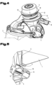
- FIG. 6 to 9 An embodiment of a protective hood 1 according to the invention which can be recognized as advantageous is further provided with a bag-like protuberance 14 which is present in the protective hood 1 at a distance from the breathing air filter 4 and which bulges from the outside to the inside of the protective hood 1 and has a size and a shape in order to be designed to receive the breathing air filter 4 from the direction of the outside of the protective hood 1.
- Fig. 6 which shows an early phase of putting on a protective hood 1 according to the invention
- the protective hood 1 is initially folded up, with the inside facing out.
- the breathing air filter 4 is also housed in the protrusion 14, protected against dirt and contamination, so that the area of the breathing air filter can also be easily touched when handling the protective hood 1.
- the breathing air filter 4 can still be left in the protrusion 14 and, as already explained above, placed on the intake port 6 of the housing 5.
- the protective hood 1 is then further extended and pulled over the head and support structure 7, lifting the protrusion 14 off the breathing air filter 4 and thus exposing it.
- This phase is Fig. 7 or in a variant regarding the position of the breathing air filter 4 in relation to the support structure 7 in Fig. 8 shown.
- FIG. 9 Finally, the fully fitted protective hood 1 with the breathing air filter 4 attached and fixed to the housing 5 is shown in a rear view, where the now inwardly directed protrusion 14 can also be seen, in which the breathing air filter 4 was accommodated when the protective hood 1 was folded up.
- the protective hood 1 can be safely grasped for packaging and/or disposal by the uncontaminated inner side, which is now on the outside.
- the protective hood assembly 1 can thus be put on and/or taken off in the shortest possible time and is easy and quick to handle. It also allows for simple and contamination-free removal of the lining without the need for additional assistance.
Landscapes
- Health & Medical Sciences (AREA)
- General Health & Medical Sciences (AREA)
- Business, Economics & Management (AREA)
- Emergency Management (AREA)
- Toxicology (AREA)
- Pulmonology (AREA)
- Respiratory Apparatuses And Protective Means (AREA)
Applications Claiming Priority (1)
| Application Number | Priority Date | Filing Date | Title |
|---|---|---|---|
| ATA50863/2023A AT527053B1 (de) | 2023-10-24 | 2023-10-24 | Schutzhauben-Anordnung |
Publications (1)
| Publication Number | Publication Date |
|---|---|
| EP4545149A1 true EP4545149A1 (fr) | 2025-04-30 |
Family
ID=93014356
Family Applications (1)
| Application Number | Title | Priority Date | Filing Date |
|---|---|---|---|
| EP24208424.2A Pending EP4545149A1 (fr) | 2023-10-24 | 2024-10-23 | Agencement de capot de protection |
Country Status (2)
| Country | Link |
|---|---|
| EP (1) | EP4545149A1 (fr) |
| AT (1) | AT527053B1 (fr) |
Citations (6)
| Publication number | Priority date | Publication date | Assignee | Title |
|---|---|---|---|---|
| GB2448522A (en) * | 2007-04-18 | 2008-10-22 | Avon Polymer Prod Ltd | Gas adsorption air filtering fan |
| US20150297920A1 (en) * | 2012-11-30 | 2015-10-22 | Koken Ltd. | Air blower and protective suit including the same |
| WO2022081439A1 (fr) * | 2020-10-13 | 2022-04-21 | Gilz Llc | Protection de tête munie d'une filtration d'air intégrée |
| US20220184427A1 (en) * | 2020-12-10 | 2022-06-16 | Flexsys Inc. | Respiratory pump arrangement for personal respiratory isolation and method of use |
| WO2022248341A1 (fr) | 2021-05-28 | 2022-12-01 | Tb-Safety Ag | Ensemble cagoule de protection |
| WO2023111522A1 (fr) * | 2021-12-13 | 2023-06-22 | Manchester University NHS Foundation Trust | Dispositif respiratoire |
Family Cites Families (2)
| Publication number | Priority date | Publication date | Assignee | Title |
|---|---|---|---|---|
| US6374823B1 (en) * | 2000-03-14 | 2002-04-23 | Mohammed Ali Hajianpour | Disposable ventilated face shield and head covering |
| US7832396B2 (en) * | 2005-06-10 | 2010-11-16 | Radium Incorporated | High air flow powered air purifying anti-contamination device |
-
2023
- 2023-10-24 AT ATA50863/2023A patent/AT527053B1/de active
-
2024
- 2024-10-23 EP EP24208424.2A patent/EP4545149A1/fr active Pending
Patent Citations (6)
| Publication number | Priority date | Publication date | Assignee | Title |
|---|---|---|---|---|
| GB2448522A (en) * | 2007-04-18 | 2008-10-22 | Avon Polymer Prod Ltd | Gas adsorption air filtering fan |
| US20150297920A1 (en) * | 2012-11-30 | 2015-10-22 | Koken Ltd. | Air blower and protective suit including the same |
| WO2022081439A1 (fr) * | 2020-10-13 | 2022-04-21 | Gilz Llc | Protection de tête munie d'une filtration d'air intégrée |
| US20220184427A1 (en) * | 2020-12-10 | 2022-06-16 | Flexsys Inc. | Respiratory pump arrangement for personal respiratory isolation and method of use |
| WO2022248341A1 (fr) | 2021-05-28 | 2022-12-01 | Tb-Safety Ag | Ensemble cagoule de protection |
| WO2023111522A1 (fr) * | 2021-12-13 | 2023-06-22 | Manchester University NHS Foundation Trust | Dispositif respiratoire |
Also Published As
| Publication number | Publication date |
|---|---|
| AT527053A4 (de) | 2024-10-15 |
| AT527053B1 (de) | 2024-10-15 |
Similar Documents
| Publication | Publication Date | Title |
|---|---|---|
| DE69719868T2 (de) | Herstellungsverfahren für eine Nadelschutzvorrichtung | |
| EP2618854B1 (fr) | Contenant stérile | |
| DE60035033T2 (de) | Flügel -i.v.-set | |
| DE2515778A1 (de) | Operationshaube, insbesondere fuer aerzte | |
| DE102010048316B4 (de) | Beatmungseinrichtung mit einer Halterung für Sprechventile und/oder Wärme-Feuchtigkeitstauscher ohne Kanülenbefestigung | |
| DE69015047T2 (de) | Spuckbecher. | |
| EP4347054B1 (fr) | Ensemble cagoule de protection | |
| DE102012215116A1 (de) | Atemschutzhaube | |
| EP3725338B1 (fr) | Récipient stérile médical | |
| DE102015224986A1 (de) | Sterileinheit für ein medizinisches Gerät | |
| EP3058967A1 (fr) | unité de tire-lait et connecteur pour un tire-lait | |
| AT527053B1 (de) | Schutzhauben-Anordnung | |
| DE102012003983A1 (de) | Siebkorb und Siebkorbverkleidung | |
| DE3413906A1 (de) | Gehaeuse fuer gasfilterkanister | |
| DE2421530C2 (fr) | ||
| EP4275730B1 (fr) | Filtre de gaz respiratoire remplaçable | |
| AT527052B1 (de) | Schutzhauben-Anordnung | |
| DE3903974C2 (fr) | ||
| WO2013156017A1 (fr) | Cagoule de protection pour salles blanches | |
| EP2684655B1 (fr) | Appareil et méthode pour prolonger la durée de vie d'un manchon pour boîte à gant | |
| DE202021004084U1 (de) | Angetriebene luftreinigende Atemschutzgeräteanordnung | |
| WO2013104449A2 (fr) | Unité fermable pour isolateur ou salle blanche | |
| DE9417169U1 (de) | Vorrichtung zum Filtern und gegebenenfalls Befeuchten der Atemluft von Patienten | |
| DE102016110764A1 (de) | Sammelbehälter zur Aufnahme von Gewebeproben und/oder Polypen | |
| AT18637U1 (de) | Schutzhauben-Anordnung |
Legal Events
| Date | Code | Title | Description |
|---|---|---|---|
| PUAI | Public reference made under article 153(3) epc to a published international application that has entered the european phase |
Free format text: ORIGINAL CODE: 0009012 |
|
| STAA | Information on the status of an ep patent application or granted ep patent |
Free format text: STATUS: THE APPLICATION HAS BEEN PUBLISHED |
|
| AK | Designated contracting states |
Kind code of ref document: A1 Designated state(s): AL AT BE BG CH CY CZ DE DK EE ES FI FR GB GR HR HU IE IS IT LI LT LU LV MC ME MK MT NL NO PL PT RO RS SE SI SK SM TR |
|
| STAA | Information on the status of an ep patent application or granted ep patent |
Free format text: STATUS: REQUEST FOR EXAMINATION WAS MADE |
|
| 17P | Request for examination filed |
Effective date: 20251023 |