EP4545158A1 - Element longitudinal d'une barriere de delimitation pour une de patinoire - Google Patents
Element longitudinal d'une barriere de delimitation pour une de patinoire Download PDFInfo
- Publication number
- EP4545158A1 EP4545158A1 EP24208090.1A EP24208090A EP4545158A1 EP 4545158 A1 EP4545158 A1 EP 4545158A1 EP 24208090 A EP24208090 A EP 24208090A EP 4545158 A1 EP4545158 A1 EP 4545158A1
- Authority
- EP
- European Patent Office
- Prior art keywords
- board
- barrier
- ice
- lighting unit
- ice surface
- Prior art date
- Legal status (The legal status is an assumption and is not a legal conclusion. Google has not performed a legal analysis and makes no representation as to the accuracy of the status listed.)
- Pending
Links
Images

Classifications
-
- A—HUMAN NECESSITIES
- A63—SPORTS; GAMES; AMUSEMENTS
- A63C—SKATES; SKIS; ROLLER SKATES; DESIGN OR LAYOUT OF COURTS, RINKS OR THE LIKE
- A63C19/00—Design or layout of playing courts, rinks, bowling greens or areas for water-skiing; Covers therefor
- A63C19/10—Ice-skating or roller-skating rinks; Slopes or trails for skiing, ski-jumping or tobogganing
-
- A—HUMAN NECESSITIES
- A63—SPORTS; GAMES; AMUSEMENTS
- A63C—SKATES; SKIS; ROLLER SKATES; DESIGN OR LAYOUT OF COURTS, RINKS OR THE LIKE
- A63C19/00—Design or layout of playing courts, rinks, bowling greens or areas for water-skiing; Covers therefor
- A63C19/06—Apparatus for setting-out or dividing courts
- A63C19/08—Mechanical means for marking-out
-
- A—HUMAN NECESSITIES
- A63—SPORTS; GAMES; AMUSEMENTS
- A63C—SKATES; SKIS; ROLLER SKATES; DESIGN OR LAYOUT OF COURTS, RINKS OR THE LIKE
- A63C19/00—Design or layout of playing courts, rinks, bowling greens or areas for water-skiing; Covers therefor
- A63C19/06—Apparatus for setting-out or dividing courts
- A63C19/08—Mechanical means for marking-out
- A63C2019/085—Fences; Nets; Barriers
-
- A—HUMAN NECESSITIES
- A63—SPORTS; GAMES; AMUSEMENTS
- A63C—SKATES; SKIS; ROLLER SKATES; DESIGN OR LAYOUT OF COURTS, RINKS OR THE LIKE
- A63C2203/00—Special features of skates, skis, roller-skates, snowboards and courts
- A63C2203/12—Electrically powered or heated
-
- A—HUMAN NECESSITIES
- A63—SPORTS; GAMES; AMUSEMENTS
- A63C—SKATES; SKIS; ROLLER SKATES; DESIGN OR LAYOUT OF COURTS, RINKS OR THE LIKE
- A63C2203/00—Special features of skates, skis, roller-skates, snowboards and courts
- A63C2203/14—Lighting means
-
- F—MECHANICAL ENGINEERING; LIGHTING; HEATING; WEAPONS; BLASTING
- F21—LIGHTING
- F21W—INDEXING SCHEME ASSOCIATED WITH SUBCLASSES F21K, F21L, F21S and F21V, RELATING TO USES OR APPLICATIONS OF LIGHTING DEVICES OR SYSTEMS
- F21W2131/00—Use or application of lighting devices or systems not provided for in codes F21W2102/00-F21W2121/00
- F21W2131/10—Outdoor lighting
- F21W2131/105—Outdoor lighting of arenas or the like
-
- F—MECHANICAL ENGINEERING; LIGHTING; HEATING; WEAPONS; BLASTING
- F21—LIGHTING
- F21Y—INDEXING SCHEME ASSOCIATED WITH SUBCLASSES F21K, F21L, F21S and F21V, RELATING TO THE FORM OR THE KIND OF THE LIGHT SOURCES OR OF THE COLOUR OF THE LIGHT EMITTED
- F21Y2103/00—Elongate light sources, e.g. fluorescent tubes
- F21Y2103/10—Elongate light sources, e.g. fluorescent tubes comprising a linear array of point-like light-generating elements
-
- F—MECHANICAL ENGINEERING; LIGHTING; HEATING; WEAPONS; BLASTING
- F21—LIGHTING
- F21Y—INDEXING SCHEME ASSOCIATED WITH SUBCLASSES F21K, F21L, F21S and F21V, RELATING TO THE FORM OR THE KIND OF THE LIGHT SOURCES OR OF THE COLOUR OF THE LIGHT EMITTED
- F21Y2115/00—Light-generating elements of semiconductor light sources
- F21Y2115/10—Light-emitting diodes [LED]
Definitions
- the invention relates to a barrier element for a barrier of an ice skating rink, a barrier for an ice skating rink, an ice skating rink, a use of a barrier element for an ice skating rink and a method for illuminating an ice surface.
- Ice skating is a sport that has always enjoyed immense popularity. In addition to the sheer sensation of gliding across the ice, the effects of the room's atmosphere also contribute to the experience. Lighting plays a particularly important role in this context.
- the lighting primarily serves to help the ice skaters see each other better, a targeted type of lighting can also create effects that make ice skating a special experience, e.g. colored light effects at an ice disco.
- ceiling lights have typically been used in ice rinks with a symmetrical ice surface or individual rinks.
- Other types of effect lighting are very rare, and lighting that directly utilizes the ice surface as part of the effect is unknown.
- a barrier element according to the invention serves as an element for a barrier of an ice rink.
- These barriers are assembled from several elements, preferably using similar elements. However, differently shaped elements can also be used, e.g., straight and curved elements. Long and short elements can also be used.
- a rink barrier element comprises a rink barrier body which, when properly positioned, is oriented perpendicular to the ground and whose longitudinal axis is parallel to the ground. It is designed to act as a barrier for ice skaters when properly positioned.
- the rink barrier element has an elongated lighting unit along the rink's longitudinal axis, which is arranged such that its main beam direction is inclined away from the rink barrier body at a downward beam angle of at least 25° and at most 75°.
- Board elements are generally known in the art. However, the board element according to the invention has a special lighting unit. Like other board elements, this board element also comprises a board body which, when properly positioned, is aligned perpendicular to the ground.
- the board body is a flat element or an arrangement of elements, in particular slats, a net, or a grid, in a plane. Even though a board element can lie flat during storage or transport (board body parallel to the ground), the vertical position (board body perpendicular to the ground and surface normal of the board body parallel to the ice surface) is the functionally normal position.
- the board body can be formed from a single panel, which may have holes, but is often used for attaching flat advertising elements, but can also be made from slats, tubes, a grid, a net, or another arrangement of elongated or flat elements in a single plane.
- the longitudinal axis of the board body usually the axis of its longest dimension, is aligned parallel to the ground in a functionally normal setup (and lies on the side surface of the board body).
- the board body is designed to act as a barrier for ice skaters when properly positioned. This is achieved, for example, by the aforementioned construction.
- the board element is preferably higher than 0.5 m, in particular higher than 0.8 m, and most preferably at least 1 m high.
- the board element has an elongated lighting unit along the aforementioned longitudinal axis of the board body (aligned parallel to the ground).
- the term "along” means that the lighting unit follows the longitudinal axis, but does not necessarily have to be aligned parallel to it.
- the lighting unit For example, it can be wavy or zigzag-shaped or slightly oblique to the longitudinal axis, in particular at a maximum of 20°, preferably at a maximum of 10°. However, a parallel alignment to the longitudinal axis is preferred. It should be noted that in a curved band element, the longitudinal axis is curved along the curvature of the band body.
- the lighting unit is arranged so that its main beam direction, i.e., the direction in which the maximum intensity is emitted, or the central beam direction, has a specific beam angle.
- the beam angle is downward, which means that when the board element is positioned as intended (i.e., with the board body vertical), it shines downwards rather than upwards. Since there is a designated underside of the board body, namely the side that faces downwards, i.e., toward the ice surface, when the board element is positioned as intended, "downward" means that the main beam direction (obliquely) is toward the underside of the board body.
- the main beam direction is inclined towards the boards at an angle of between 25° and 75°. A good beam direction would be 45°, for example.
- the beam angle should be understood as pointing away from the boards (and not towards the boards). Because the light from the lighting unit hits the ice surface at an angle (when the board element is set up at an ice rink), the light can be coupled into the ice surface and is then slightly directed away from the boards before it exits. It should be noted that one cannot fundamentally assume an idealized image of a flat, transparent surface onto which the light beam hits. Due to unevenness, e.g. driving on the ice surface, the light in the light cone of the lighting unit is coupled into the ice surface at very different local angles. Part of it is reflected directly and part is refracted.
- part of the refracted light exits the ice surface directly after being reflected off the ground, while another part is totally reflected (due to a flat angle of incidence caused by unevenness) and only exits again after traveling a certain distance (possibly due to an angle of reflection caused by unevenness). All of this creates the effect of a glowing ice surface, which creates a special atmosphere while skating and significantly increases safety.
- main radiation direction preferably refers to the main radiation direction of a light source, i.e., an element that generates light. In the case of an LED, this main radiation direction is usually perpendicular to the emitting surface of the LED. In particular, “main radiation direction” does not refer to the average radiation direction of a partially shaded light cone, but rather to the direction of the (unshaded) light cone.
- a barrier according to the invention for an ice rink comprises a plurality of barrier elements according to the invention.
- these can be uniform, but preferably the barrier is composed of differently shaped barrier elements, e.g., straight barrier elements (possibly of different lengths) and curved or bent barrier elements.
- An ice rink according to the invention comprises an ice surface and a barrier according to the invention.
- This barrier separates a number of areas of the ice surface from a number of other areas. In the simplest case, an ice surface is separated from an outside area. However, it can also happen that individual ice rinks are separated from each other as areas by the barrier.
- the barrier is arranged such that the lighting units of the barrier elements are aligned with their main radiation direction obliquely to the ice surface, i.e., they radiate obliquely downwards away from the body of the barrier.
- the invention also provides for the use of barrier elements according to the invention for separating one area of an ice surface from another area and for illuminating the ice surface with the lighting units with a main radiation direction of light oblique to the ice surface, preferably for an ice skating rink.
- a method according to the invention serves to illuminate an ice surface with a board element according to the invention.
- Light from the lighting unit is radiated onto the ice surface at an angle such that a portion of the light, in particular more than 10%, is coupled into the ice surface. This occurs by radiating light obliquely downwards from a properly positioned board element at the specified radiation angle of the main radiation direction (between 25° and 75°).
- a preferred barrier element is characterized by the fact that the main radiation direction is inclined at a radiation angle of at least 30°.
- the radiation angle is even more obtuse, namely at least 35°, in particular at least 40°.
- the radiation angle should be considered the angle between a baseline orthogonal to the underside of the barrier body (parallel to the vertical when the barrier element is positioned as intended) and a line tilted relative to it about the longitudinal axis.
- a preferred board element is characterized by the fact that the main radiation direction is inclined to the board body at a radiation angle of no more than 70°, preferably no more than 60°, and in particular no more than 55°.
- a particularly preferred radiation angle is 45°. At such an angle, light couples very well into the ice surface without dazzling skaters.
- the lighting unit is arranged at least 20 cm from the underside of the board body.
- the lighting unit is preferably arranged at least 30 cm, in particular at least 40 cm, from the underside of the board body.
- the lighting unit is preferably positioned at least 20 cm, preferably at least 30 cm, and especially at least 40 cm from the top of the barrier body.
- a good position for the lighting unit is below half the height of the barrier body, e.g., in the lower third.
- the height position of the lighting unit appropriately, e.g. by designing the lighting unit and the barrier body in such a way that the position of the lighting unit on the barrier element can be varied.
- the board can be designed so that a slat equipped with a lighting unit can be mounted at different heights. This allows the illumination width of the ice surface to be taken into account and the intensity of the light to penetrate the ice. This effect can be varied, particularly along the length of a board, creating a unique lighting effect.
- the lighting unit comprises a number of support strips equipped with luminous elements, in particular LEDs, on their upper side.
- a support strip can be formed, in particular, from a wooden board, a metal plate, or a plastic plate, e.g., from a circuit board strip made of epoxy resin or an aluminum strip.
- the luminous elements are then preferably arranged in a linear arrangement on the support strip. It is preferred that each luminous element has a conical radiation characteristic with a main radiation direction, wherein the main radiation direction of substantially each of the luminous elements of the lighting unit has an above-mentioned radiation angle (between 25° and 75°).
- substantially means more than 80%, in particular more than 90%, of the luminous elements, preferably all luminous elements.
- the lighting unit is designed such that half the aperture angle of its light cone is smaller than the beam angle of the main beam direction toward the board body. This means that its light cone is so small that it does not illuminate the board body.
- the barrier body is formed from a plurality of slats.
- the lighting unit is attached to the underside of one of the slats. It is preferred that the lighting unit comprises a plurality of support strips with luminous elements whose main radiation direction is aligned parallel to the surface normal of the support strips.
- the support strips are preferably attached to a beveled side of the respective slat or to a beveled surface of a support structure.
- a support structure can, for example, be a triangular profile strip, e.g. with the cross-section of a right-angled triangle, to whose hypotenuse the lighting unit is attached.
- a preferred barrier element comprises a post on at least one of its two end faces.
- a barrier element can have a post on each side, in which case two posts would adjoin each other at the barrier, or just one post, in which case the barrier body of an adjacent barrier element would be attached to the post of one barrier element.
- the post preferably projects beyond the lighting unit in the direction of the surface normal of the barrier body. This basically means that the post is preferably thicker than the barrier body with the lighting unit.
- the post preferably projects beyond the barrier body on all sides orthogonal to its longitudinal axis. The post is therefore preferably thicker and higher than the barrier body. This means that the barrier element with its lighting unit is somewhat protected by the post.
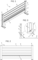
- Figure 1 shows a barrier element 1 for a barrier of an ice rink. It comprises a barrier body 2, which, in the intended positioning shown here, is aligned perpendicular to the ground, and whose longitudinal axis A is aligned parallel to the ground.
- the barrier body 2 is formed here from a total of five slats 6, which in this example are all arranged parallel and slightly spaced from one another between two bars 4. It is quite possible that one of the bars 4 already belongs to an adjacent barrier element 1.
- the bars are provided with feet 5 at the bottom, which can be screwed onto a floor surface. For later use (see e.g. Figure 3 ) the feet 5 would be (at least partially) covered by an ice surface E.
- Figure 3 is the band element 1 of the Figure 1 once again in side view with a transparent bar 4.
- the underside of the second bar 6 is bevelled from below and the lighting unit 3 is mounted obliquely on the bar so that its main radiation direction H (arrow) is inclined away from the board body 2 at a radiation angle W of at least 25° and at most 75° (here approx. 45°).
- the lighting unit 3 is basically formed by a linear arrangement of luminous elements L, e.g., LEDs, on a carrier strip T.
- This carrier strip T is then arranged obliquely on the underside of the slat 6 in order to obtain an oblique main radiation direction.
- Figure 4 shows the coupling of light in a band element 1 according to the invention as it is shown, for example, in the Figures 1 to 3
- a cone of light rays S strikes an ice surface E.
- the Figure 3 can be considered as an example.
- a large portion of the light rays is reflected by the surface of the ice surface E (solid arrows), but another portion penetrates the rough surface into the ice surface E (dashed arrows) and is refracted several times. This is possible because the rough surface causes the local angles of incidence of the light rays S into the ice surface E to vary. This creates the impression that the edges of the ice surface are glowing.
Landscapes
- Engineering & Computer Science (AREA)
- Architecture (AREA)
- Civil Engineering (AREA)
- Structural Engineering (AREA)
- Non-Portable Lighting Devices Or Systems Thereof (AREA)
Applications Claiming Priority (1)
| Application Number | Priority Date | Filing Date | Title |
|---|---|---|---|
| DE102023129113.0A DE102023129113A1 (de) | 2023-10-23 | 2023-10-23 | Bandenelement für eine Bande einer Eislaufbahn |
Publications (1)
| Publication Number | Publication Date |
|---|---|
| EP4545158A1 true EP4545158A1 (fr) | 2025-04-30 |
Family
ID=93257813
Family Applications (1)
| Application Number | Title | Priority Date | Filing Date |
|---|---|---|---|
| EP24208090.1A Pending EP4545158A1 (fr) | 2023-10-23 | 2024-10-22 | Element longitudinal d'une barriere de delimitation pour une de patinoire |
Country Status (2)
| Country | Link |
|---|---|
| EP (1) | EP4545158A1 (fr) |
| DE (1) | DE102023129113A1 (fr) |
Citations (4)
| Publication number | Priority date | Publication date | Assignee | Title |
|---|---|---|---|---|
| EP3165263A1 (fr) * | 2015-11-06 | 2017-05-10 | Ice-World Holding B.V. | Séparateur pour une patinoire |
| JP2017118953A (ja) * | 2015-12-28 | 2017-07-06 | 株式会社ドリームファクトリーワールドワイド | 格闘技用リング設備 |
| WO2021028671A2 (fr) * | 2019-08-09 | 2021-02-18 | Murphy Stuart Frank | Terrain de jeu |
| US20210372580A1 (en) * | 2017-09-22 | 2021-12-02 | Nlx | Device for lighting a court and corresponding lighting strip |
Family Cites Families (4)
| Publication number | Priority date | Publication date | Assignee | Title |
|---|---|---|---|---|
| DE1845336U (de) * | 1961-11-02 | 1962-01-18 | Miniatur Golf Betr S Ges Alber | Ball- oder kugelspielbahn. |
| DE102011000402A1 (de) * | 2010-10-25 | 2012-04-26 | Emde Projects Gmbh | Beleuchtungsvorrichtung |
| DE202015001949U1 (de) * | 2015-05-08 | 2015-05-20 | Stephan Ratte-Polle | Spielfeldleuchte für Tischfussballgeräte mit Spielstangen |
| DE102019129471A1 (de) * | 2019-10-31 | 2021-05-06 | Intercom - Dr. Leitner Srl | Handlauf für eine Bande |
-
2023
- 2023-10-23 DE DE102023129113.0A patent/DE102023129113A1/de active Pending
-
2024
- 2024-10-22 EP EP24208090.1A patent/EP4545158A1/fr active Pending
Patent Citations (4)
| Publication number | Priority date | Publication date | Assignee | Title |
|---|---|---|---|---|
| EP3165263A1 (fr) * | 2015-11-06 | 2017-05-10 | Ice-World Holding B.V. | Séparateur pour une patinoire |
| JP2017118953A (ja) * | 2015-12-28 | 2017-07-06 | 株式会社ドリームファクトリーワールドワイド | 格闘技用リング設備 |
| US20210372580A1 (en) * | 2017-09-22 | 2021-12-02 | Nlx | Device for lighting a court and corresponding lighting strip |
| WO2021028671A2 (fr) * | 2019-08-09 | 2021-02-18 | Murphy Stuart Frank | Terrain de jeu |
Also Published As
| Publication number | Publication date |
|---|---|
| DE102023129113A1 (de) | 2025-04-24 |
Similar Documents
| Publication | Publication Date | Title |
|---|---|---|
| EP2264359A2 (fr) | Luminaire | |
| DE29909282U1 (de) | Leuchte | |
| EP3171081B1 (fr) | Profilé d'éclairage et éclairage d'étagère comprenant un tel profilé d'éclairage | |
| EP1314928B1 (fr) | Distributeur de lumière, dispositif d'éclairage avec au moins un distributeur de lumière et méthode de production d'un distributeur de lumière | |
| DE102023129113A1 (de) | Bandenelement für eine Bande einer Eislaufbahn | |
| DE10311492B3 (de) | Leuchtschiene mit Leuchtdioden | |
| DE2612046A1 (de) | Bremsvorrichtung fuer skier | |
| AT16319U1 (de) | Optisches System sowie Anordnung zur Lichtabgabe | |
| EP4051394B1 (fr) | Barrière et main courante, méthode d'érection d'un équipement sportif mobile | |
| WO2012055519A1 (fr) | Dispositif d'éclairage pour la zone extérieure | |
| EP0516976A2 (fr) | Balise lumineuse | |
| DE102014105150A1 (de) | Zaun sowie Überwachungsvorrichtung | |
| EP2716964B1 (fr) | Lampe à DEL | |
| DE60012674T2 (de) | Abwehrvorrichtung für Vögel, wie zum Beispiel Tauben, auf einer Fläche | |
| CH459521A (de) | Metallrost und Verfahren zur Herstellung desselben | |
| DE2203825A1 (de) | Leuchtdecke | |
| DE202022102623U1 (de) | Trennwand-Paneel, und Trennwand | |
| DE202018102168U1 (de) | Flache LED-Leuchte | |
| DE60217018T2 (de) | Werbevorrichtung und Methode zur Befestigung eines folienförmigen Werbeträgers auf dieser Werbevorrichtung | |
| DE102021100662A1 (de) | Anordnung zur Beleuchtung einer Rasenflächenbegrenzung | |
| DE662665C (de) | Reklamevorrichtung | |
| DE202025105362U1 (de) | Akustiklamelle sowie Akustikstruktur in einem Raum | |
| DE19821762B4 (de) | Standleuchte mit variabler Abstrahlcharakteristik | |
| AT503261A1 (de) | Leuchtenanordnung sowie daraus hergestellter sichtschutz bzw. raumteiler | |
| CH697568B1 (de) | Holzbalken, damit gebildetes Holzelement und Verfahren zur Herstellung derselben. |
Legal Events
| Date | Code | Title | Description |
|---|---|---|---|
| PUAI | Public reference made under article 153(3) epc to a published international application that has entered the european phase |
Free format text: ORIGINAL CODE: 0009012 |
|
| STAA | Information on the status of an ep patent application or granted ep patent |
Free format text: STATUS: THE APPLICATION HAS BEEN PUBLISHED |
|
| AK | Designated contracting states |
Kind code of ref document: A1 Designated state(s): AL AT BE BG CH CY CZ DE DK EE ES FI FR GB GR HR HU IE IS IT LI LT LU LV MC ME MK MT NL NO PL PT RO RS SE SI SK SM TR |
|
| STAA | Information on the status of an ep patent application or granted ep patent |
Free format text: STATUS: REQUEST FOR EXAMINATION WAS MADE |
|
| 17P | Request for examination filed |
Effective date: 20251027 |