EP4545177A1 - Ensemble étanche et son procédé de fabrication - Google Patents
Ensemble étanche et son procédé de fabrication Download PDFInfo
- Publication number
- EP4545177A1 EP4545177A1 EP23306865.9A EP23306865A EP4545177A1 EP 4545177 A1 EP4545177 A1 EP 4545177A1 EP 23306865 A EP23306865 A EP 23306865A EP 4545177 A1 EP4545177 A1 EP 4545177A1
- Authority
- EP
- European Patent Office
- Prior art keywords
- bag
- wall
- overmolding
- protective envelope
- connector
- Prior art date
- Legal status (The legal status is an assumption and is not a legal conclusion. Google has not performed a legal analysis and makes no representation as to the accuracy of the status listed.)
- Pending
Links
Images




Classifications
-
- B—PERFORMING OPERATIONS; TRANSPORTING
- B01—PHYSICAL OR CHEMICAL PROCESSES OR APPARATUS IN GENERAL
- B01L—CHEMICAL OR PHYSICAL LABORATORY APPARATUS FOR GENERAL USE
- B01L1/00—Enclosures; Chambers
- B01L1/02—Air-pressure chambers; Air-locks therefor
-
- B—PERFORMING OPERATIONS; TRANSPORTING
- B01—PHYSICAL OR CHEMICAL PROCESSES OR APPARATUS IN GENERAL
- B01L—CHEMICAL OR PHYSICAL LABORATORY APPARATUS FOR GENERAL USE
- B01L2200/00—Solutions for specific problems relating to chemical or physical laboratory apparatus
- B01L2200/02—Adapting objects or devices to another
- B01L2200/025—Align devices or objects to ensure defined positions relative to each other
-
- B—PERFORMING OPERATIONS; TRANSPORTING
- B01—PHYSICAL OR CHEMICAL PROCESSES OR APPARATUS IN GENERAL
- B01L—CHEMICAL OR PHYSICAL LABORATORY APPARATUS FOR GENERAL USE
- B01L2200/00—Solutions for specific problems relating to chemical or physical laboratory apparatus
- B01L2200/12—Specific details about manufacturing devices
-
- B—PERFORMING OPERATIONS; TRANSPORTING
- B01—PHYSICAL OR CHEMICAL PROCESSES OR APPARATUS IN GENERAL
- B01L—CHEMICAL OR PHYSICAL LABORATORY APPARATUS FOR GENERAL USE
- B01L2200/00—Solutions for specific problems relating to chemical or physical laboratory apparatus
- B01L2200/14—Process control and prevention of errors
- B01L2200/141—Preventing contamination, tampering
-
- B—PERFORMING OPERATIONS; TRANSPORTING
- B01—PHYSICAL OR CHEMICAL PROCESSES OR APPARATUS IN GENERAL
- B01L—CHEMICAL OR PHYSICAL LABORATORY APPARATUS FOR GENERAL USE
- B01L2300/00—Additional constructional details
- B01L2300/12—Specific details about materials
- B01L2300/123—Flexible; Elastomeric
Definitions
- the present invention relates to sealed containers in the pharmaceutical or biotechnological field.
- the invention relates to leaktight containers used in leaktight assemblies between a sterile chamber such as an isolator and one or more of these containers.
- a sterile chamber comprising several doors, and to connect, to these doors, containers themselves provided with doors. The doors are opened after the sterile chamber and the external container have been connected, to allow the objects contained in the container to be transferred to the sterile chamber, or even in the opposite direction if appropriate.
- a bag comprising a wall of flexible film
- the wall of the bag defining an internal volume of the bag, where the wall of the bag is welded, at an access opening, to an overmolding of a connection system
- the connection system comprising a connector adapted for mechanical connection to a complementary connector of a sterile chamber in order to establish a sterile communication between the bag and the chamber, the connector comprising a portion for attachment to the bag, the connection system further comprising an overmolding molded over the attachment portion.
- this second type of container can also be exposed to high levels of stress, particularly in terms of pressure and negative pressure.
- this second type of container may be subjected to stresses during transport, particularly in terms of pressure variation (for example variation in external pressure with respect to the internal pressure when the container is filled).
- pressure variation for example variation in external pressure with respect to the internal pressure when the container is filled.
- These stresses can, in some situations, cause the container to lose some pressure.
- Such pressure loss can cause difficulties, for example during visual inspections of the container and its contents, more specifically when the container is inserted into an overpack, in which vacuum has been done. More specifically, a problem may also arise when the container is over-wrapped with an extra bag and a vacuum is created between the two bags. If the bag swells, sterility is lost (hence the overwrapping used in some cases).
- Such stresses can also potentially cause problems with the connector, leading to excess pressure in the connector itself at some points.
- the leaktight assembly which comprises:
- the invention relates to a leaktight container comprising a leaktight assembly, the second access opening being closed in a leaktight manner.
- a leaktight assembly comprising a container wherein the connector is a first connector, the leaktight assembly further comprising a rigid chamber comprising a second connector complementary to the first connector, the connector of the leaktight container being connected in a leaktight manner to the second connector of said rigid chamber after at least part of the protective envelope is removed.
- the overmolding selected in a suitable material, allows welding the wall of the bag and the wall of the protective envelope to said overmolding in order to create a good seal for the container so produced.
- the connector of the leaktight assembly is protected during use.
- the leaktight container so produced can be sterilized with steam or gamma irradiation.
- the invention relates to a method for manufacturing a leaktight container further comprising a step of closing the protective envelope, at its sealing opening, after a door has been positioned at the connection system.
- the invention relates to a method for manufacturing a leaktight container further comprising a step of filling the bag by the second access opening, and a step of closing the second access opening of the bag so as to close the bag in a leaktight manner at its second access opening after closing the assembly in a leaktight manner at the connector and filling the bag.
- the present invention relates to leaktight containers and to their manufacturing for pharmaceutical or biotechnological applications requiring limited or no contamination, including by particles from the external environment.
- This typically involves a bag whose contents are to be isolated from the external environment, assembled to another chamber such as an isolator, for a sterile transfer between the bag and the chamber.
- a typical application would be to use such a container for the sterile transfer of packaging material or syringe stoppers from a bag within which they are initially contained and sterilized, to an isolator.
- FIG. 1 shows a leaktight container.
- Said container comprises a leaktight assembly of which the second access opening 20 is closed in a leaktight manner.
- the leaktight assembly comprises a bag 1 comprising a wall 8 of flexible film, the wall 8 of said bag defining an internal volume V of said bag, said bag 1 having two opposite ends, a first access opening 10 adapted for placing the internal volume of the bag in communication with the outside of the bag at the first end, a second access opening 20 adapted for placing the internal volume of the bag in communication with the outside of the bag at the second end.
- the bag 1 comprises an inner surface 6 facing towards the internal volume V.
- the bag 1 comprises an outer surface 7 opposite to the inner surface 6.
- the container also comprises a connection system 9 which includes a connector 21 comprising an attachment portion 210 and an overmolding 40 molded on the attachment portion 210.
- the wall of the bag is positioned facing the overmolding at the first access opening 10, the wall of the bag being welded to the overmolding 40.
- the second access opening 20 of said bag 1 is closed in a leaktight manner.
- the protective envelope 15 may be flexible.
- the protective envelope 15 may be welded on the overmolding 40, on top of the bag 1 (on the external, layer of the film of the bag 1 which is welded on the overmolding 40), or under the bag 1 (i.e. internal layer of the film of the bag 1 on the external layer of the protective envelope which is itself welded on the overmolding 40), or side-by-side of the bag 1 (both films are welded on the overmolding 40 at different locations), depending on the configuration.
- the protective envelope 15 is sealed on the overmolding 40 for example during the manufacturing process of the leaktight container, as exposed herein after.
- the protective envelope 15 is closed in a leaktight manner at its end.
- the protective envelope 15 may also be closed during use i.e., after the internal volume of the bag is filled, for example for ensuring an equality of the internal pressures of the bag and of the protective envelope.
- the connector 21 is thus protected against soiling / dirtiness, contamination and against various sources and effects of constraints that may be applied to the connector 21, this protection is active immediately at manufacturing.
- Said assembly may be closed in a leaktight manner at the connector 21.
- Said assembly may in particular be connected to a complementary connector of a sterile chamber, such an assembly between the connectors enabling a sterile communication between the contents of the bag 1 and the chamber 11.
- This connection to the complementary connector can be done after a dedicated portion of the sealed (closed) protective envelope 15 is removed, either by cutting or pealing the protective envelope.
- the attachment portion 210 is located at the access opening of the bag 1 and surrounds a space for passage 24 between the bag 1 and the chamber 11 at the access opening 10.
- the assembly thus formed may for example be removable and transportable, for example for one-time use, the assembly being small and the bag being flexible, which reduces the space requirements for transport and delivery of these containers.
- the second access opening 20 is then closed in a leaktight manner, thereby forming a bag, in particular after introducing products into the bag 1.
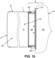
- the second access opening 20 is closed by a closing surface 2, the closing surface 2 being adapted to attach to the wall of the bag 1 at its second access opening 20 ( FIG. 1b ).
- the closing surface 2 being adapted to attach to the wall of the bag 1 at its second access opening 20 ( FIG. 1b ).
- Essentially all points on the circumference of the sealing surface 2 are welded together at ideally one point.
- the internal volume V of said bag 1 is filled with material to be introduced into the chamber 11, for example items such as syringe stoppers.
- material to be introduced into the chamber 11 for example items such as syringe stoppers.
- the contents of the container thus formed are then sterilized with gamma irradiation for example.
- Sterilization may for example take place through the wall 8 of the bag. Sterilization may also take place through the wall of the protective envelope 15. A portion of the wall of the bag 1 (respectively protective envelope 15) may for example be of Tyvec ® which is a vapor-permeable material. The bag is for example then enclosed in over-packaging to guarantee sterility until use.
- FIG. 2A illustrates a top view of a flattened bag 1.
- this bag 1 comprises a bottleneck 16 which materialises the predetermined location at which the bag 1 is welded to the connector 21 (the bottleneck is thus the location at which the connecter 21 is welded on the overmolding 40).
- the width of this bottleneck 16 is greater or equal to the width of the connector 21 and more particularly is greater or equal to the width formed by the overmolding 40, so that the wall of the bag, can be welded at its bottleneck 16, to the overmolding 40, in a closed and continuous manner along the entire length of the bottleneck 16.
- the process for manufacturing the leaktight container using this first embodiment of the bag is illustrated below.
- the protective envelope 15 is an additional part which is added and is not part of the bag 1.
- Figure 2B illustrates this embodiment.
- the protective envelope 15 may be made of a different material to that of the bag 1.
- the process for manufacturing the leaktight container according to this embodiment is illustrated below.
- the protective envelope 15 comprise a connector opening 151, sensibly of the length of the overmolding 40, so that the wall of the protective envelope 15, can be welded at its connector opening 151, to the overmolding 40, in a closed and continuous manner along the entire length of the connector opening 151.
- the protective envelope 15 also comprises a sealing opening 152, that can also be closed in a leaktight manner, thereby forming a protection around the connection system 9.
- the protective envelope 15 may be removed, for example for allowing the connector 21 to be connected to a complementary connector.
- a part of the protective envelope 15 is pealable for example at a predetermined location.
- the protective envelope 15 may be cut by an operator.
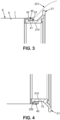
- the connector 21 comprises a radially outer surface 22 facing radially outward of the connector 21, and the overmolding 40 comprises a radially inner surface 41 and a radially outer surface 42 opposite to the radially inner surface 41 of the overmolding 40.
- the radially outer surface 42 may be divided in two sections: one for the welding of the bag and one for the welding of the protective envelope.
- the bag 1 comprises an inner surface 6 facing towards the internal volume V.
- the radially outer surface 22 of the connector 21 is facing the radially inner surface 41 of the overmolding 40, such that during the step of positioning the overmolding 40 to face the wall of the bag 1, the radially outer surface 42 of the overmolding 40 is also positioned facing the inner surface 6 of the bag 1.
- the passage between the bag 1 and the outside is composed of the superposition, from inside to outside, of the thickness of the connector 21 at its attachment portion, the thickness of the overmolding, and the thickness of the wall of the bag 1.
- the protective envelope 15 also comprises, in an embodiment, an inner surface facing towards the internal volume V2.
- the radially outer surface 22 of the connector 21 is facing the radially inner surface 41 of the overmolding 40, such that during the step of positioning the overmolding 40 to face the wall of the protective envelope 15, the radially outer surface 42 of the overmolding 40 is also positioned facing the inner surface of the protective envelope 15.
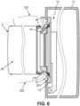
- the protective envelope 15 end extends longitudinally beyond the connector 21, as illustrated by the doted lines 221 and 222.
- the wall 8 of the bag is of flexible film and is welded to the overmolding 40 in a closed continuous manner all along the first access opening 10.
- the wall of the protective envelope 15 is of flexible film and is welded to the overmolding 40 in a closed continuous manner all along the first connector opening 151.
- the attachment portion 210 of the connector 21 may comprise a body 70 with a projecting member 202 which extends radially from said main body 70.
- Said projecting member 202 is adapted to be encapsulated in the overmolding 40.
- the thickness of the body at the projecting member 202 is typically two to three times greater than that of the body where there is no projecting member.
- a first method for manufacturing the assembly, for the first embodiment of the bag 1 ( fig 2a ), is shown in FIG. 5a and comprises the following steps:
- FIG. 5b A second method for manufacturing the assembly, for the second embodiment of the bag 1 ( fig 2b ), is shown in FIG. 5b and comprises the following steps:
- the steps of welding the wall of the bag 1, at its first access opening 10, and the step of welding the wall of the protective envelope 15, at its connector opening 151 to the overmolding 40 are carried out together.
- the protective envelope 15 takes place over the bag 1, and a single welding step is carried out.
- the method thus comprises:
- a portion of the overmolding 40 is set to weld the wall of the bag 1, at its first access opening 10 and a complementary portion of the overmolding 40 is set to weld the wall of the protective envelope 15.
- the outer surface of the overmolding 40 is divided in two parts, and each of these two parts are used to weld the wall of the bag 1 for the first part and the protective envelope 15 for the second part.
- the closure of the protective envelope 15, at the sealing opening 152 can be carried out upstream, i.e., before the protective envelope is welded to the overmolding 40.
- the closure of the protective envelope 15, at the sealing opening 152 can be carried out upstream, i.e., before the protective envelope is welded to the overmolding 40.
- the closure of the protective envelope 15, at the sealing opening 152 is carried out after the sealing of the protective envelope on the overmolding 40.
- the overmolding 40 is annular.
- the weld is then a circular weld.
- a connector 21 made of polycarbonate (PC) or acrylonitrile butadiene styrene (ABS) or polyvinylidene fluoride (PVDF) or polybutylene terephthalate (PBT).
- PC polycarbonate
- ABS acrylonitrile butadiene styrene
- PVDF polyvinylidene fluoride
- PBT polybutylene terephthalate
- Such materials for the connector 21 will be rigid so as to withstand the locking forces from the second connector and will be resistant to the various treatments associated with sterilization by steam (at temperatures below 125° C.), gamma irradiation, or ethylene oxide.
- the plastic film may in particular be polyethylene (PE), high density polyethylene (HDPE), or low-density polyethylene (LDPE).
- the overmolding 40 will be made of polyethylene (PE), high density polyethylene (HDPE), or in the form of thermoplastic elastomer (TPE), or may be of thermoplastic elastomer or polypropylene or polyvinylidene fluoride (PVDF).
- the overmolding 40 made of such materials provides poor resistance during sterilization ( ⁇ 125° C.) and will also tend to deform at welding working temperatures above 120° C., its mechanical strength being inadequate at these temperatures, but it will not melt during the temperature increase when it is mounted on the connector which will then "contain" its deformation.
- the welding of the plastic film on the overmolding has good resistance to gamma irradiation sterilization or steam sterilization.
- the film and the overmolding begin to melt almost at the same time, therefore within similar temperature ranges of about 120° C. (far from the welding temperatures of the materials selected for the connector 21 which instead are about 200° C.).
- the connector 21 comprises for example a first door 14 adapted for equipping the access opening 10 of the bag 1.
- the first door 14 comprises a flange-shaped frame 200, the attachment portion 210 forming at least a portion of the flange 200.
- the protective envelope is then sealed at its sealing opening 152, as exposed herein before.
- a leaktight assembly by assembling the leaktight container described above to a chamber 11. This is done by first pealing or cutting the protective envelope 15 (the rest of which being illustrated by references 221 and 222 on figure 6 ) and then connecting the connector to a complementary connector at the chamber. Such a temporary assembly may enable for example a clean transfer of biopharmaceutical content between the bag thus formed and the chamber 11.
- the chamber 11 also comprises for example a second door 12, comprising a flange-shaped frame 201, said second door 12 being adapted for equipping an access opening 13 of said chamber 11 and being complementary to the first door 14.
- each door may be circular, the diametrical dimension of the second door 12 being greater than the dimension of the opening formed in the flange 200 for the first door.
- Each door is provided with sealing means with its flange, such as a compressible O-ring carried by the flange and engaging with a seat of said door.
- Each door is also associated with means for locking in the closed position on its flange.
- the flange 201 of the second door is integral with a plurality of longitudinal fingers projecting outwards and able to engage with circular notches formed in the periphery of the flange 200 of the first door.
- each of the doors is locked to its flange.
- the flange of the first door 200 is brought against that of the second door 201 where it is initially positioned by the fingers and then conclusively by engagement of a central boss of the second door in a recess of the first door.
- the two flanges are then locked together in the so-called coupled position, then the two doors are unlocked to allow communication between the bag and the chamber 11.
- one of the chambers consists for example of an isolator and the bag contains one or more objects or a load to be transferred when in the coupled position, through the passage thus formed between the two chambers, for example to supply the clean room with items or products required for the fabrication or production underway in the clean room, or conversely to eliminate trash or products from said clean room.
- the bag may contain sterile objects, plugs, tubes, syringe plungers.
- the overmolding is assembled to one side of the plastic film by adjusting the diameter of the hole to the elasticity of the film used, enabling an assembly of the connector referred to as flat assembly.
Landscapes
- Health & Medical Sciences (AREA)
- Clinical Laboratory Science (AREA)
- Chemical & Material Sciences (AREA)
- Chemical Kinetics & Catalysis (AREA)
- Packages (AREA)
- Making Paper Articles (AREA)
Priority Applications (2)
| Application Number | Priority Date | Filing Date | Title |
|---|---|---|---|
| EP23306865.9A EP4545177A1 (fr) | 2023-10-25 | 2023-10-25 | Ensemble étanche et son procédé de fabrication |
| PCT/EP2024/077950 WO2025087673A1 (fr) | 2023-10-25 | 2024-10-04 | Ensemble étanche et son procédé de fabrication |
Applications Claiming Priority (1)
| Application Number | Priority Date | Filing Date | Title |
|---|---|---|---|
| EP23306865.9A EP4545177A1 (fr) | 2023-10-25 | 2023-10-25 | Ensemble étanche et son procédé de fabrication |
Publications (1)
| Publication Number | Publication Date |
|---|---|
| EP4545177A1 true EP4545177A1 (fr) | 2025-04-30 |
Family
ID=88697490
Family Applications (1)
| Application Number | Title | Priority Date | Filing Date |
|---|---|---|---|
| EP23306865.9A Pending EP4545177A1 (fr) | 2023-10-25 | 2023-10-25 | Ensemble étanche et son procédé de fabrication |
Country Status (2)
| Country | Link |
|---|---|
| EP (1) | EP4545177A1 (fr) |
| WO (1) | WO2025087673A1 (fr) |
Citations (5)
| Publication number | Priority date | Publication date | Assignee | Title |
|---|---|---|---|---|
| FR2721289A1 (fr) | 1994-06-17 | 1995-12-22 | Idc Isolateur Denominateur | Dispositif de jonction étanche entre deux enceintes isolées d'un milieu extérieur. |
| EP0997154A1 (fr) * | 1998-11-01 | 2000-05-03 | Newform N.V. | Conteneur stérilisable avec adaptateur stérilisable pour l'accostage à un port d'un système d'isolation |
| DE19983093B4 (de) * | 1998-04-03 | 2007-01-25 | Becton Dickinson France | Vorrichtung zum Herstellen einer Kommunikation zwischen zwei Kammern und zum gleichzeitigen Aufrechterhalten der Dichtigkeit |
| US20120117920A1 (en) * | 2008-06-09 | 2012-05-17 | Beton Dickinson France S.A.S. | Sterile packing and sterilization method using this packing |
| US20180369801A1 (en) * | 2015-12-23 | 2018-12-27 | Sartorius Stedim Aseptics | Method for manufacturing a leaktight container |
-
2023
- 2023-10-25 EP EP23306865.9A patent/EP4545177A1/fr active Pending
-
2024
- 2024-10-04 WO PCT/EP2024/077950 patent/WO2025087673A1/fr active Pending
Patent Citations (5)
| Publication number | Priority date | Publication date | Assignee | Title |
|---|---|---|---|---|
| FR2721289A1 (fr) | 1994-06-17 | 1995-12-22 | Idc Isolateur Denominateur | Dispositif de jonction étanche entre deux enceintes isolées d'un milieu extérieur. |
| DE19983093B4 (de) * | 1998-04-03 | 2007-01-25 | Becton Dickinson France | Vorrichtung zum Herstellen einer Kommunikation zwischen zwei Kammern und zum gleichzeitigen Aufrechterhalten der Dichtigkeit |
| EP0997154A1 (fr) * | 1998-11-01 | 2000-05-03 | Newform N.V. | Conteneur stérilisable avec adaptateur stérilisable pour l'accostage à un port d'un système d'isolation |
| US20120117920A1 (en) * | 2008-06-09 | 2012-05-17 | Beton Dickinson France S.A.S. | Sterile packing and sterilization method using this packing |
| US20180369801A1 (en) * | 2015-12-23 | 2018-12-27 | Sartorius Stedim Aseptics | Method for manufacturing a leaktight container |
Also Published As
| Publication number | Publication date |
|---|---|
| WO2025087673A1 (fr) | 2025-05-01 |
Similar Documents
| Publication | Publication Date | Title |
|---|---|---|
| US10843184B2 (en) | Method for manufacturing a leaktight container | |
| US3519158A (en) | Aseptic connector and closure | |
| US9463690B2 (en) | Neck assembly | |
| US20070084524A1 (en) | Container with valve assembly, and apparatus and method for filling | |
| ZA200502121B (en) | Sealed containers and methods of making and filling same | |
| US6749808B1 (en) | Sterilizable container with a sterilizable adapter for docking to a port of an isolation system | |
| US12440659B2 (en) | Dual ended disinfecting cap for stopcock valves | |
| TWI875991B (zh) | 用於兩個封閉空間之間的雙門密封連接系統的子組件及其製造方法與用於雙門密封連接系統的轉移裝置 | |
| CN114632006B (zh) | 用于保护管状物的方法 | |
| US11690784B2 (en) | Biopharmaceutical container, biopharmaceutical container bag, and method for the production and use of said biopharmaceutical container | |
| JP5380609B2 (ja) | 口部材付き袋及びその接続構造 | |
| WO2025087673A1 (fr) | Ensemble étanche et son procédé de fabrication | |
| EP2420219B1 (fr) | Port d'administration | |
| EP4129360A1 (fr) | Corps de seringue médicale et son emballage | |
| FI110755B (fi) | Infuusiosäiliö jossa on kaksi liitäntää | |
| AU6655500A (en) | Plastic closure for vials and other medical containers | |
| CN115697557A (zh) | 密封转移容器的凸缘 | |
| EP4520362A1 (fr) | Couvre-porte stérile pour transfert de bouchon médical | |
| US11852246B2 (en) | Valve assembly and method of producing the same | |
| EP3586966B1 (fr) | Fermetures de récipient et leurs procédés d'utilisation et de fabrication | |
| HK40079880A (en) | Beta-container for alpha-beta location system | |
| WO2025049511A1 (fr) | Couvercle de protection pour récipient pour le transfert de composants stérilisés | |
| JPH0443489Y2 (fr) | ||
| AU2012254948A1 (en) | Sealed containers and methods of making and filling same |
Legal Events
| Date | Code | Title | Description |
|---|---|---|---|
| PUAI | Public reference made under article 153(3) epc to a published international application that has entered the european phase |
Free format text: ORIGINAL CODE: 0009012 |
|
| STAA | Information on the status of an ep patent application or granted ep patent |
Free format text: STATUS: THE APPLICATION HAS BEEN PUBLISHED |
|
| AK | Designated contracting states |
Kind code of ref document: A1 Designated state(s): AL AT BE BG CH CY CZ DE DK EE ES FI FR GB GR HR HU IE IS IT LI LT LU LV MC ME MK MT NL NO PL PT RO RS SE SI SK SM TR |
|
| STAA | Information on the status of an ep patent application or granted ep patent |
Free format text: STATUS: REQUEST FOR EXAMINATION WAS MADE |
|
| 17P | Request for examination filed |
Effective date: 20251006 |