EP4545178A1 - Dispositif et procédé de préparation de gouttelettes - Google Patents
Dispositif et procédé de préparation de gouttelettes Download PDFInfo
- Publication number
- EP4545178A1 EP4545178A1 EP23844963.1A EP23844963A EP4545178A1 EP 4545178 A1 EP4545178 A1 EP 4545178A1 EP 23844963 A EP23844963 A EP 23844963A EP 4545178 A1 EP4545178 A1 EP 4545178A1
- Authority
- EP
- European Patent Office
- Prior art keywords
- chip
- pressure
- droplet
- inlet
- control module
- Prior art date
- Legal status (The legal status is an assumption and is not a legal conclusion. Google has not performed a legal analysis and makes no representation as to the accuracy of the status listed.)
- Pending
Links
Images




Classifications
-
- B—PERFORMING OPERATIONS; TRANSPORTING
- B01—PHYSICAL OR CHEMICAL PROCESSES OR APPARATUS IN GENERAL
- B01L—CHEMICAL OR PHYSICAL LABORATORY APPARATUS FOR GENERAL USE
- B01L3/00—Containers or dishes for laboratory use, e.g. laboratory glassware; Droppers
- B01L3/50—Containers for the purpose of retaining a material to be analysed, e.g. test tubes
- B01L3/502—Containers for the purpose of retaining a material to be analysed, e.g. test tubes with fluid transport, e.g. in multi-compartment structures
- B01L3/5027—Containers for the purpose of retaining a material to be analysed, e.g. test tubes with fluid transport, e.g. in multi-compartment structures by integrated microfluidic structures, i.e. dimensions of channels and chambers are such that surface tension forces are important, e.g. lab-on-a-chip
-
- B—PERFORMING OPERATIONS; TRANSPORTING
- B01—PHYSICAL OR CHEMICAL PROCESSES OR APPARATUS IN GENERAL
- B01L—CHEMICAL OR PHYSICAL LABORATORY APPARATUS FOR GENERAL USE
- B01L3/00—Containers or dishes for laboratory use, e.g. laboratory glassware; Droppers
- B01L3/02—Burettes; Pipettes
- B01L3/0241—Drop counters; Drop formers
-
- B—PERFORMING OPERATIONS; TRANSPORTING
- B01—PHYSICAL OR CHEMICAL PROCESSES OR APPARATUS IN GENERAL
- B01L—CHEMICAL OR PHYSICAL LABORATORY APPARATUS FOR GENERAL USE
- B01L3/00—Containers or dishes for laboratory use, e.g. laboratory glassware; Droppers
- B01L3/50—Containers for the purpose of retaining a material to be analysed, e.g. test tubes
- B01L3/502—Containers for the purpose of retaining a material to be analysed, e.g. test tubes with fluid transport, e.g. in multi-compartment structures
- B01L3/5027—Containers for the purpose of retaining a material to be analysed, e.g. test tubes with fluid transport, e.g. in multi-compartment structures by integrated microfluidic structures, i.e. dimensions of channels and chambers are such that surface tension forces are important, e.g. lab-on-a-chip
- B01L3/50273—Containers for the purpose of retaining a material to be analysed, e.g. test tubes with fluid transport, e.g. in multi-compartment structures by integrated microfluidic structures, i.e. dimensions of channels and chambers are such that surface tension forces are important, e.g. lab-on-a-chip characterised by the means or forces applied to move the fluids
-
- C—CHEMISTRY; METALLURGY
- C12—BIOCHEMISTRY; BEER; SPIRITS; WINE; VINEGAR; MICROBIOLOGY; ENZYMOLOGY; MUTATION OR GENETIC ENGINEERING
- C12Q—MEASURING OR TESTING PROCESSES INVOLVING ENZYMES, NUCLEIC ACIDS OR MICROORGANISMS; COMPOSITIONS OR TEST PAPERS THEREFOR; PROCESSES OF PREPARING SUCH COMPOSITIONS; CONDITION-RESPONSIVE CONTROL IN MICROBIOLOGICAL OR ENZYMOLOGICAL PROCESSES
- C12Q1/00—Measuring or testing processes involving enzymes, nucleic acids or microorganisms; Compositions therefor; Processes of preparing such compositions
- C12Q1/68—Measuring or testing processes involving enzymes, nucleic acids or microorganisms; Compositions therefor; Processes of preparing such compositions involving nucleic acids
- C12Q1/6844—Nucleic acid amplification reactions
- C12Q1/686—Polymerase chain reaction [PCR]
-
- B—PERFORMING OPERATIONS; TRANSPORTING
- B01—PHYSICAL OR CHEMICAL PROCESSES OR APPARATUS IN GENERAL
- B01L—CHEMICAL OR PHYSICAL LABORATORY APPARATUS FOR GENERAL USE
- B01L2300/00—Additional constructional details
- B01L2300/04—Closures and closing means
- B01L2300/041—Connecting closures to device or container
- B01L2300/042—Caps; Plugs
-
- B—PERFORMING OPERATIONS; TRANSPORTING
- B01—PHYSICAL OR CHEMICAL PROCESSES OR APPARATUS IN GENERAL
- B01L—CHEMICAL OR PHYSICAL LABORATORY APPARATUS FOR GENERAL USE
- B01L2300/00—Additional constructional details
- B01L2300/04—Closures and closing means
- B01L2300/046—Function or devices integrated in the closure
- B01L2300/048—Function or devices integrated in the closure enabling gas exchange, e.g. vents
-
- B—PERFORMING OPERATIONS; TRANSPORTING
- B01—PHYSICAL OR CHEMICAL PROCESSES OR APPARATUS IN GENERAL
- B01L—CHEMICAL OR PHYSICAL LABORATORY APPARATUS FOR GENERAL USE
- B01L2300/00—Additional constructional details
- B01L2300/14—Means for pressure control
-
- B—PERFORMING OPERATIONS; TRANSPORTING
- B01—PHYSICAL OR CHEMICAL PROCESSES OR APPARATUS IN GENERAL
- B01L—CHEMICAL OR PHYSICAL LABORATORY APPARATUS FOR GENERAL USE
- B01L2300/00—Additional constructional details
- B01L2300/18—Means for temperature control
-
- B—PERFORMING OPERATIONS; TRANSPORTING
- B01—PHYSICAL OR CHEMICAL PROCESSES OR APPARATUS IN GENERAL
- B01L—CHEMICAL OR PHYSICAL LABORATORY APPARATUS FOR GENERAL USE
- B01L2400/00—Moving or stopping fluids
- B01L2400/04—Moving fluids with specific forces or mechanical means
- B01L2400/0475—Moving fluids with specific forces or mechanical means specific mechanical means and fluid pressure
- B01L2400/0487—Moving fluids with specific forces or mechanical means specific mechanical means and fluid pressure fluid pressure, pneumatics
-
- B—PERFORMING OPERATIONS; TRANSPORTING
- B01—PHYSICAL OR CHEMICAL PROCESSES OR APPARATUS IN GENERAL
- B01L—CHEMICAL OR PHYSICAL LABORATORY APPARATUS FOR GENERAL USE
- B01L3/00—Containers or dishes for laboratory use, e.g. laboratory glassware; Droppers
- B01L3/50—Containers for the purpose of retaining a material to be analysed, e.g. test tubes
- B01L3/502—Containers for the purpose of retaining a material to be analysed, e.g. test tubes with fluid transport, e.g. in multi-compartment structures
- B01L3/5027—Containers for the purpose of retaining a material to be analysed, e.g. test tubes with fluid transport, e.g. in multi-compartment structures by integrated microfluidic structures, i.e. dimensions of channels and chambers are such that surface tension forces are important, e.g. lab-on-a-chip
- B01L3/502769—Containers for the purpose of retaining a material to be analysed, e.g. test tubes with fluid transport, e.g. in multi-compartment structures by integrated microfluidic structures, i.e. dimensions of channels and chambers are such that surface tension forces are important, e.g. lab-on-a-chip characterised by multiphase flow arrangements
- B01L3/502784—Containers for the purpose of retaining a material to be analysed, e.g. test tubes with fluid transport, e.g. in multi-compartment structures by integrated microfluidic structures, i.e. dimensions of channels and chambers are such that surface tension forces are important, e.g. lab-on-a-chip characterised by multiphase flow arrangements specially adapted for droplet or plug flow, e.g. digital microfluidics
- B01L3/502792—Containers for the purpose of retaining a material to be analysed, e.g. test tubes with fluid transport, e.g. in multi-compartment structures by integrated microfluidic structures, i.e. dimensions of channels and chambers are such that surface tension forces are important, e.g. lab-on-a-chip characterised by multiphase flow arrangements specially adapted for droplet or plug flow, e.g. digital microfluidics for moving individual droplets on a plate, e.g. by locally altering surface tension
Definitions
- the present application relates to the technical field of a biochip, and particularly to a droplet preparation device and a droplet preparation method.
- a droplet is produced by a droplet preparation device, which includes a chip provided in a cavity. In the cavity, the droplet is produced in the chip by applying a varied pressure in the chip.
- a droplet preparation device which includes a chip provided in a cavity. In the cavity, the droplet is produced in the chip by applying a varied pressure in the chip.
- pressure fluctuation since merely the pressure is regulated for controlling production of the droplets. Therefore, there will be a problem of poor droplet production quality, uneven size of droplets, and the like.
- an objective of the present application is providing a droplet preparation device and a droplet preparation method, which can improve the quality of droplets as produced.
- the droplet preparation device further includes a vent cap.
- a vent cap When the vent cap is directly connected to the sample inlet, an air inlet channel is formed between an inner surface of the vent cap and an outer surface of the chip close to the sample inlet; and a bottom of the air inlet channel acts as an inlet end, and a top end thereof is in communication with the sample inlet.
- the vent cap and the perforated cap can be alternatively connected with the two chip ports; when the vent cap and the perforated cap are separately connected to the two chip ports, a top surface of the perforated cap is higher than that of the vent cap, the pressing assembly is pressed to cover a top surface of the vent hole to cover a first chip port directly connected to the perforated cap, and a second chip port is in communication with the cavity; and wherein when the vent cap is directly connected to the oil inlet, an air outlet channel is formed between the inner surface of the vent cap and the outer surface of the chip close to the oil inlet; and the bottom of the air inlet channel acts as an outlet end, and a top end thereof is in communication with the oil inlet.
- a part of a top surface of the first chip port directly connected to the perforated cap is covered by the perforated cap, and a remaining part thereof is in communication with the vent hole.
- the chip includes an inlet arm, an outlet arm and a bottom arm provided between a bottom of the inlet arm and a bottom of the outlet arm to form a U-shaped structure by the inlet arm, the outlet arm and the bottom arm; the top end of the inlet arm acts as the sample inlet, and the top end of the outlet arm acts as the oil inlet.
- the chip is attached onto a top surface of the temperature control module under pressure.
- a droplet preparation method conducted by using the above droplet preparation device includes:
- At least one adjusting step is a second adjusting step, including only adjusting the pressing force against the perforated cap by the pressing assembly.
- At least one adjusting step is a third adjusting step, including adjusting the temperature value by controlling the temperature control module while adjusting the pressing force against the perforated cap by the pressing assembly.
- the method further includes: controlling the pressing assembly to cover the vent hole to cover the sample inlet, and providing a negative pressure to the oil inlet through the cavity, so as to form the pressure difference in the chip.
- a droplet preparation device in the present application includes a cavity, a chip, a pressure detection unit, a temperature control module, a pressing assembly and a perforated cap; the chip, the temperature control module and the pressure detection unit are provided in the cavity, the temperature control module is configured for adjusting the temperature value in the chip, and the pressure detection unit is configured for detecting the pressure data in the cavity; the top of the chip has two chip ports acting as a sample inlet and an oil inlet respectively; the perforated cap has a vent hole penetrating through the perforated cap along an up-down direction and is configured to elastically deformed along the up-down direction under a pressing force to change a volume of the vent hole.
- the vent hole is in communication with the oil inlet, and the pressing assembly is lifted or lowered to open or cover the top end of the vent hole by the lifting motion to open or cover the oil inlet correspondingly.
- the pressing assembly covers the oil inlet, a positive pressure can be applied by the cavity into the chip through the sample inlet to form a pressure difference in the chip.
- the pressure data can be detected by the pressure detection unit in real time, and the temperature value can be adjusted by controlling the temperature control module and/or a pressing condition of the pressing assembly can be adjusted to adjust a production speed and droplet size of droplet during droplet production, which can eliminate an impact on the droplet production due to a difference between current pressure data and the preset pressure data, so as to improve the quality of droplets as produced.
- the pressure difference between the sample inlet and the oil inlet reaches an equilibrium by slowly lifting the pressing assembly until it leave the perforated cap.
- the droplet production is stopped, the droplets stop moving, and air exhausting is performed via an exhaust hole in the cavity to reach an equilibrium between the pressures inside and outside the cavity, so that a large number of droplets can be produced uniformly and quickly.
- a droplet preparation device in a first aspect, includes a housing, and a chip, a pressing assembly and a temperature control module provided in the housing; the temperature control module is provided at a bottom of the housing, the chip is provided on the temperature control module, the pressing assembly is provided on a top of the housing, and the temperature control module is configured to cooperate with the pressing assembly for adjusting a droplet size.
- the housing is connected to an external pressure source, and a pressure detection unit is provided between the housing and the pressure source.
- the chip is defined with a sample inlet and an oil inlet
- a perforated cap is provided at the oil inlet of the chip, and has a vent hole penetrating through the perforated cap along a vertical direction, and the perforated cap is configured to cooperate with the pressing assembly for adjusting the pressure in the chip.
- the perforated cap is sleeved on the chip, and the perforated cap is an elastic component.
- a projection of the vent hole is within a projection range of the oil inlet in a plane where the chip is located.
- the pressing assembly includes a pressing motor and a pressing plate, the pressing motor is fixedly connected to the housing and slidably connected to the pressing plate, and a projection of the perforated cap is within a projection range of the pressing plate in the plane where the chip is located.
- the sample inlet of the chip is provided with a vent cap sleeved on the chip, the vent cap has an air inlet channel leading to the chip and in communication with the chip.
- the chip includes an inlet arm and an outlet arm, both the inlet arm and the outlet arm are fixedly connected to the chip and extend towards the pressing plate, the sample inlet is provided at a lower end of the inlet arm, and the oil inlet is located at a lower end of the outlet arm.
- a droplet preparation method including the following steps:
- the present application can achieve at least one of the following technical effects:
- the present application aims to provide a droplet preparation device and a preparation method thereof, which can improve the quality droplet as produced.
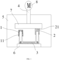
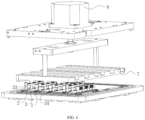
- the droplet preparation device includes a cavity 5, a chip 3, a pressure detection unit 9, a temperature control module 6, a pressing assembly 4 and a perforated cap 2.
- the cavity 5 is connected with a pressure source 10, and a pressure in a sealed cavity 5 can be changed.
- the pressure source 10 can be a positive pressure device or a negative pressure device, configured for pressurizing the sealed cavity 5 or releasing a pressure within the sealed cavity 5.
- An electromagnetic relief valve can also be provided in the sealed cavity 5, which is configured to control the pressure in the sealed cavity 5 precisely in combination with the pressure source 10.
- the chip 3, the temperature control module 6 and a pressure detection unit 9 are all provided in the cavity 5. Specifically, the temperature control module 6 and the pressure detection unit 9 are positioned outside the chip 3.
- the chip 3 is a specifically a microfluidic chip.
- the chip 3 has two chip ports provided at the top thereof, which are an sample inlet 31 and an oil inlet 32.
- a pressure working chamber is formed in the cavity 5, which can provide a pressure into the chip 3 through the sample inlet 31 and the oil inlet 32 which are in communication with the pressure working chamber.
- the chip 3 is filled with an oil phase before producing the droplet.
- a sample is introduced from the sample inlet 31, and passed droplet through a micro-channel in the chip 3 under the pressure to generate droplets, which are dispersed in the oil phase. Meanwhile, part of the oil phase flows into the oil inlet 32.
- the pressure detection unit 9 is configured for detecting the pressure data in the cavity 5.
- an ideal pressure controlling diagram of the cavity 5 is shown in FIG.3 , in which the pressure is stable and ascends smoothly.
- the pressure controlling curve of the cavity 5 is shown in FIG. 4 , in which one specific pressure data is fluctuated, assuming uncertainty. Based on the results of detection, the pressure in the cavity 5 or other parameters influencing droplet production can be adjusted, so as to improve the quality of droplets as produced, and achieve a quick and stable droplet production, solving a problem of non-uniform droplet size due to pressure fluctuation.
- the temperature control module 6 is configured for adjusting the temperature value in the chip 3, which is mainly used to alleviate droplet size variation due to a pressure fluctuation in the cavity, so as to achieve an objective of obtaining uniform droplet size in combination with pressure controlling.
- the temperature control module 6 can be configured as only cooling, only heating, or both cooling and heating.
- the temperature control module 6 can control the temperature at 20-55 °C when the droplet is produced, which can improve a fluidity of oil phase to promote a forward spreading of the droplets.
- the perforated cap 2 has a vent hole penetrating through the perforated cap 2 along an up-down direction, and is configured to be elastically deformed along the up-down direction under a pressing force to change a volume of the vent hole 21.
- the perforated cap 2 is prepared by an elastic material such as a rubber, a silicon rubber, polyurethane, and the like.
- the perforated cap 2 is directly connected to the oil inlet 32.
- the pressing assembly 4 includes a driving source and a pressing plate 7 connected to a bottom of the driving source, and specifically, the driving source is a pressing motor 8.
- the driving source moves the pressing plate 7 upward or downward to leave or seal the perforated cap 2.
- the vent hole 21 of the perforated cap 2 is pressed to achieve sealing and generate a pressure difference between the sample inlet 31 and oil inlet 32.
- the pressing plate 7 is moved upward, it leaves the vent hole 21 to achieve unsealing, so that the pressure difference between the sample inlet 31 and oil inlet 32 is eliminated.
- the pressing assembly 4 leaves the perforated cap 2
- the sample inlet 31 and oil inlet 32 can reach a pressure balance instantaneously.
- the perforated cap 2 When in use, the perforated cap 2 is directly connected to the oil inlet 32, the vent hole 21 comes into communication with the oil inlet 32, and the pressing assembly 4 descends to cover the top of the vent hole 21, so as to cover the oil inlet 32. After that, a positive pressure is applied into the cavity 5 through the pressure source 10, then the positive pressure is applied into the chip 3 through the sample inlet 31 by the cavity 5 to form the pressure difference, so that a large number of droplets can be quickly produced in the chip 3.
- the pressure data in the cavity 5 is detected by the pressure detection unit 9 in real time during the droplet production process.
- the temperature value in the chip 3 can be changed by the temperature control module 6 to ensure uniform droplet size by a temperature-pressure combination mode.
- the perforated cap 2 is configured to be deformable under the pressing by the pressing plate 7, so that the volume of the vent hole 21 is changed to change the pressure at an end of the oil inlet 32.
- further controlling a pressing distance of the pressing plate 7 can precisely control the pressure at the end of the oil inlet 32. Greater pressing distance of the pressing plate 7 leads to a greater pressure in the oil inlet 32; and conversely, to a smaller pressure in the oil inlet 32. Therefore, uniform droplet size can be guaranteed by temperature-pressure combination mode of the pressing assembly 4 with pressure based on the above features of the perforated cap 2.
- uniform droplet size can also be guaranteed by a mode of combining temperature, pressure and the lifting motion of the pressing assembly 4, that is, adjusting the temperature control module 6 and the pressing assembly 4 at the same time.
- the pressure detection unit 9 can detect the pressure data in real time, and control the temperature control module 6 to adjust the temperature value and/or a pressing condition of the pressing assembly 4, so as to adjust a production speed and droplet size of the droplets during droplet production, which can eliminate an impact on the droplet due to a difference between a current pressure data and the preset pressure data to improve the quality of droplets as produced. Then the pressure difference between the sample inlet and the oil inlet reaches an equilibrium by slowly lifting the pressing assembly 4 until it leaves the perforated cap 2. At this time, the droplet production is stopped, the droplets stop moving, and air exhausting is performed via an exhaust hole in the cavity 5 to reach an equilibrium between the pressures inside and outside the cavity 5, so that a large number of droplets can be produced uniformly and quickly.
- the droplet preparation device further includes a vent cap 1.
- a vent cap 1 As shown in FIG. 1 , an air inlet channel 11 is formed between an inner surface of the vent cap 1 and an outer surface of the chip 3 close to the sample inlet; and a bottom of the air inlet channel 11 acts as an inlet end, and a top end thereof is in communication with the sample inlet 31.
- the vent cap 1 is an elastic component, a hard object, a plastic or a metal part.
- air in the cavity 5 enters the bottom of the air inlet channel 11, and then enters sample inlet 31 from the top of the air inlet channel 11 to drive the sample to enter the chip 3.
- the presence of the vent cap 1 guarantees that the pressure in the cavity 5 can enter the sample inlet 31 through the air inlet channels 11. Meanwhile, the presence of the vent cap 1 controls the air of the cavity 5 to enter the sample inlet 31 through the inlet end at the bottom of the air inlet channels 11, which can prevent a large amount of unexpected substances from falling into the sample inlet 31 from above to influence the droplet production and contaminate the chip 3, achieving an objective of dust and contamination prevention.
- a top surface of the perforated cap 2 is higher than that of the vent cap 1, the pressing assembly 4 is pressed to cover a top surface of the vent hole 21 to cover a first chip port directly connected to the perforated cap 2, and a second chip port is in communication with the cavity 5.
- a lower height of the vent hole 21 than that of the perforated cap 2 facilitates the pressing assembly 4, after being pressed, to seal only the vent hole 21 and the first chip port directly connected to the vent hole 21, while the second chip port is in communication with the cavity 5.
- the perforated cap 2 a part of a top surface the first chip port directly connected to the perforated cap is covered by the perforated cap 2, and the remaining part thereof is in communication with the vent hole 21.
- vent hole 21 is a cylindrical hole, and has an optional diameter of 0.5-3mm, since a too small diameter suffers from poor processibility and blockage, and too large diameter tends to cause droplet back-flow when the pressure is released from the two chip ports of the chip 3.
- an area of the vent hole 21 is less than that of the oil inlet 32, which can prevent large particulate substances from falling into the chip 3 to negatively influence the droplet preparation.
- the vent hole 21 can prevent a droplet fusion due to a large volume change of the cavity 5 of the oil inlet 32 during ascending of the pressing assembly 4.
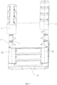
- the chip 3 includes an inlet arm 33, an outlet arm 34 and a bottom arm provided between bottom of the inlet arm 33 and bottom of the outlet arm 34 to form a U-shaped structure by the inlet arm 33, the outlet arm 34 and the bottom arm.
- the top end of the inlet arm 33 acts as the sample inlet 31, and the top end of the outlet arm 34 acts as the oil inlet 32.
- the structure is simple. Specifically, the top ends of the inlet arm 33 and the oil inlet 32 have the same heights.
- the chip 3 is attached onto a top surface of the temperature control module 6 under pressure to avoid an interference to the movement of the pressing assembly 4 and ensure a temperature control effect of the chip 3 by the temperature control module 6.
- the vent hole 21 of the perforated cap 2 is sealed by the pressing assembly 4 before the chip 3 is pressurized through the cavity 5.
- the pressure in the cavity 5 can supply a pressure to the chip 3 via the sample inlet 31, so as to generate a pressure difference across the chip 3, by which a large number of the droplets can be quickly produced in the chip 3.
- a droplet production speed can be adjusted by adjusting the pressure data of the cavity 5, the temperature value of the temperature control module 6 and the pressing distance of the pressing assembly 4, so that a large number of uniform and stable droplets can be quickly produced in a short time.
- Adopting the droplet preparation device in present application can effectively improve the droplet production speed, quickly produce a large number of droplets in a short time to meet requirements of a high-throughput test, effectively decrease a possibility of back-flowing, reduce a structure requirement of the droplet preparation device for a microfluidic chip, and achieve a low cost and easy processing of the microfluidic chip more easily.
- the droplet can be controlled by a dynamic equilibrium to ensure a stable rising and lowering of the pressure and more uniform size of droplets as produced, achieving a more reliable detection result.
- the vent cap 1 and the perforated cap 2 can be alternatively connected with the two chip ports.
- the vent cap 1 is directly connected to the oil inlet 32
- the perforated cap 2 is directly connected to the sample inlet 31, in which an air outlet channel is formed between the inner surface of the vent cap 1 and the outer surface of the chip 3 close to the oil inlet 32, and the bottom of the air inlet channel acts as an outlet end, and a top end thereof is in communication with the oil inlet 32.
- the perforated cap 2 is in communication with the sample inlet 31.
- a top surface of the perforated cap 2 is higher than that of the vent cap 1, and the pressing assembly 4 is pressed to cover the top surface of the vent hole 21 so as to cover the sample inlet 31.
- the pressing assembly 4 is pressed to cover the vent hole 21, the pressure in the cavity 5 is changed to a negative pressure, and the pressure of the oil inlet 32 is decreased, so as to form a pressure difference between the sample inlet 31 and the oil inlet 32.
- the sample enters the micro-channel from the sample inlet 31 to produce droplets, the oil phase enters the oil inlet 32 and the pressure is released from the sample inlet 31 to finish the droplet production process.
- the droplet preparation device is provided in the housing, which includes a base, the chip 3, the pressing assembly 4, the pressure detection unit 9 and the temperature control module 6.
- the housing is formed with a sealed cavity 5, provided with an airtight opening, and fixedly connected with a pressure pipe at the airtight opening connected to a pressure source 10.
- the pressure in the sealed cavity 5 can be controlled and changed by the pressure source 10.
- the pressure source 10 is configured for pressurizing the cavity 5 or releasing pressure in the cavity 5.
- An electromagnetic relief valve can also be provided in the sealed cavity 5, so as to control the pressure in the sealed cavity 5 precisely in combination with the pressure source 10.
- the pressure source 10 provides a positive pressure into the cavity 5.
- the pressing assembly 4, the chip 3, the temperature control module 6 and the base are installed in the housing from up to down along a vertical direction, and the pressure detection unit 9 is installed in the pressure pipe.
- the pressure detection unit 9 and the temperature control module 6 are electrically connected to an operation system.
- the pressure detection unit 9 can be a pressure sensor or other components for detecting a change in pressure.
- the temperature control module 6 can be a component such as a heating film or a semiconductor, and the like.
- the chip 3 includes a chip body and a chip cover plate.
- the chip body and the chip cover plate are stacked along the vertical direction and sealingly connected with each other, and a micro-channel is formed between the chip body and the chip cover plate.
- the inlet arm 33 and the outlet arm 34 extend from the chip cover plate along a direction away from the base. In this embodiment, the ends of the inlet arm 33 and the outlet arm 34 close to the pressing assembly 4 are flush with each other.
- the inlet arm 33 is formed with an inlet cavity penetrating therethrough in the vertical direction, an end of the inlet arm 33 close to the base is formed with the sample inlet 31 located at a bottom of the inlet cavity.
- An end of the inlet arm 33 away from the chip body is formed with a first connecting port located on a top of the inlet cavity.
- An area of the first connecting port is greater than that of the sample inlet 31, and the inlet arm 33 is in communication with the chip body.
- the vent cap 1 is sleeved on an end of the inlet arm 33 away from the base, and detachably connected to the inlet arm 33, by detachable connection such as threaded connection, snap-in groove connection, and the like.
- the vent cap 1 has a downward opening.
- An inner wall of the vent cap 1 is defined with an air inlet channel 11 along the vertical direction, which is in communication with the inlet cavity.
- the outlet arm 34 is provided with an oil cavity penetrating therethrough the vertical direction, an end of the outlet arm 34 away from ground is defined with the oil inlet 32 located at a bottom of the oil cavity.
- An end of the outlet arm 34 close to the chip body is defined with a second connecting port located on a top of the oil cavity. The area of the second connecting port is greater than that of the oil inlet 32, and the outlet arm 34 is in communication with the chip body.
- An end of the outlet arm 34 away from the base is detachably connected with the perforated cap 2, by detachable connection way such as threaded connection, snap-in groove connection, and the like.
- the perforated cap 2 is an elastic component.
- the perforated cap 2 has the vent hole 21 penetrating therethrough along the vertical direction.
- the perforated cap 2 is in communication with the outlet arm 34, and a projection of the perforated cap 2 along the vertical direction is within a projection range of the oil cavity.
- a reinforcing rib is fixedly connected between multiple perforated caps 2 to reduce a deformation difference between the multiple perforated caps 2.
- the pressing assembly 4 includes the driving source, a fixing board and the pressing plate 7.
- the fixing board is fixedly connected to the housing.
- the driving source is a pressing motor 8 which is electrically connected with a control device.
- the control device can be an operation system such as PLC system.
- the pressing motor 8 is fixedly installed at the top of the hosing and slidably connected to the pressing plate 7 by a screw rod.
- the pressing plate 7 is integrally formed with a pressing block facing towards the base.
- the pressing motor 8 drives the pressing plate 7 to slide towards the chip 3
- the pressing block abuts against the perforated cap 2 and covers the vent hole 21 thereof, so that a pressure difference can be produced in the chip 3 during ventilation of the sample inlet 31, thereby producing droplets by a liquid in the micro-channel.
- the pressing plate 7 continues to slide towards the chip 3, and the perforated cap 2 is elastically deformed under the pressure, so as to change the volume of the vent hole 21 and, in turn, the pressure at the oil inlet 32, and further adjust the pressure difference in the micro-channel and, in turn, the droplet size.
- the implementation principle of the embodiment is as follows.
- the pressing motor 8 is driven to drive the pressing plate 7 to descend until the pressing block abuts against the perforated cap 2 to cover the vent hole 21.
- the pressure source 10 is adjusted to form a positive pressure in the cavity 5, so that a large number of uniform droplets are quickly formed from the liquid in the micro-channel, while the oil phase flows out of the oil inlet 32.
- the pressing plate 7 is driven to continue to ascend or descend, so that the perforated cap 2 is elastically deformed under the pressure to change the volume of the vent hole 21, which can further change the pressure at the end of the oil inlet 32.
- the pressure data in the cavity 5 is detected by the pressure detection unit 9.
- the pressure in the chip 3 can be changed by changing the temperature value in the chip 3 by the temperature control module 6 and controlling the pressing assembly 4 to ensure uniform droplet size.
- the pressing plate 7 can be driven to slowly ascend until the pressing plate 7 leaves the perforated cap 2, by which the vent hole 21 is in communication with the cavity 5 again, so that the pressure difference between the sample inlet 31 and the oil inlet 32 reaches an equilibrium.
- the production of droplet is stopped, and the droplets stop moving.
- the air in the cavity 5 is released, so that the pressure difference in the cavity 5 reaches a balance with that of an external environment. Thereby, the droplets can be produced uniformly and quickly.
- the pressure provided by the pressure source 10 in the cavity 5 is a negative pressure.
- the perforated cap 2 is sleeved on the inlet arm 33, and the vent cap 1 is sleeved on the outlet arm 34.
- An experimental principle is as follows.
- the pressing assembly 4 drives the pressing plate 7 to cover the vent hole 21 and the pressure source 10 is controlled to change the pressure in the cavity 5 to a negative pressure, which decreases the pressure at the oil inlet 32 and forms the pressure difference between the sample inlet 31 and the oil inlet 32.
- the sample enters the micro-channel from the sample inlet 31 to produce the droplets under actions of the pressure difference and the temperature, while the oil phase enters the oil inlet 32.
- the pressure in the cavity 5 is restored and the pressure is released from the end where the sample inlet 31 is located to finish the production of droplets.
- the present application further provides a droplet preparation method in addition to the above droplet preparation device.
- the droplet preparation method is applied with the droplet preparation device.
- the droplet preparation device can be one of the above droplet preparation devices provided in any embodiments, and beneficial effects can be found referring to the above each embodiment.
- the droplet preparation method includes:
- performing the first adjusting step includes the following steps after selecting the first adjusting step:
- the preset pressure value is one of values within the preset pressure range, in which the maximum preset pressure deviation value is a maximum value within the preset pressure range and the minimum preset pressure deviation value is a minimum value within the preset pressure range.
- the minimum preset pressure deviation value is less than the preset pressure value, which is less than the maximum preset pressure deviation value.
- the preset pressure value and the preset pressure range at every moment can be set according to demand, which can be the same or different.
- At least one adjusting step is a second adjusting step, including only adjusting the pressing force against the perforated cap 2 by the pressing assembly 4.
- a pressing distance of the pressing plate 7 is adjusted to improve the droplet quality.
- Performing the second adjusting step includes the following steps:
- At least one adjusting step is a third adjusting step, including adjusting the temperature value by controlling the temperature control module 6 while adjusting the pressing force against the perforated cap 2 by the pressing assembly 4.
- the droplet production quality is improved by controlling temperature value of the temperature control module 6 and adjusting the pressing distance of the pressing plate 7.
- Performing the third adjusting step includes the following steps:
- controlling methods of the temperature control module 6 and the pressing plate 7 can be obtained according to an actual droplet production condition.
- a temperature adjusting method of the temperature control module 6 can be obtained from an actual test based on factors such as different structures of the chip 3, oil phase composition, and the like.
- a compression value of a descending distance of the pressing plate 7 relative to the perforated cap 2 can be obtained through an actual test based on factors such as different structures of the perforated cap 2.
- the droplet preparation method further includes controlling the pressing assembly 4 to cover the vent hole 21 to further cover the sample inlet 31, and supplying a negative pressure into the oil inlet 32 through the cavity 5 to form the pressure difference in the chip 3.
- the droplet size can be controlled precisely according to the following empirical formulas of a model for multiple-parameter controlling the droplet production.
- a model for multiple-parameter controlling the droplet production During the pressure ascending stage of the droplet production, it should try to ensure an actual droplet size equal to a theoretical droplet value and uniform actual droplet size.
- the pressure descending stage of the droplet production it should effectively control an average distribution of the produced droplets in the chip 3, minimize droplet backflow and excessively air injection, so as to avoid significant variation in the total number of droplets and impaired accuracy of the result.
- the formula is applied at the pressure ascending stage of the droplet production. After the pressing plate 7 is in sealed contact with the perforated cap 2, when ⁇ d ⁇ 0, the pressure in the cavity 5 begins to ascend, p ⁇ 1 is detected by the pressure detection unit 9, so the droplet begins to be produced.
- the actual radius of the droplet r consisting with the theoretical radius of the droplet R and the even droplet can be obtained through continuously monitoring the p value, and controlling the descending or ascending of ⁇ d and the temperature control module 6.
- the formula is applied at the pressure releasing stage of the droplet production.
- the pressure of the cavity 5 begins to descend, and a descend value of p is detected by the pressure detection unit 9.
- a descend value of p is detected by the pressure detection unit 9.
- it can effectively maintain an average distribution of the produced droplets in the chip 3, minimize droplet backflow and excessively air injection by dynamically monitoring the p value, controlling the descending or ascending of ⁇ d and the temperature control module 6, which results in significant variability in a total number of droplets and affects an accuracy of the result.
Landscapes
- Chemical & Material Sciences (AREA)
- Health & Medical Sciences (AREA)
- Chemical Kinetics & Catalysis (AREA)
- Clinical Laboratory Science (AREA)
- Analytical Chemistry (AREA)
- General Health & Medical Sciences (AREA)
- Dispersion Chemistry (AREA)
- Hematology (AREA)
- Organic Chemistry (AREA)
- Life Sciences & Earth Sciences (AREA)
- Engineering & Computer Science (AREA)
- Proteomics, Peptides & Aminoacids (AREA)
- Zoology (AREA)
- Wood Science & Technology (AREA)
- Physics & Mathematics (AREA)
- Microbiology (AREA)
- Molecular Biology (AREA)
- Immunology (AREA)
- Biotechnology (AREA)
- Biophysics (AREA)
- Biochemistry (AREA)
- Bioinformatics & Cheminformatics (AREA)
- General Engineering & Computer Science (AREA)
- Genetics & Genomics (AREA)
- Sampling And Sample Adjustment (AREA)
Applications Claiming Priority (2)
| Application Number | Priority Date | Filing Date | Title |
|---|---|---|---|
| CN202210895822.5A CN115254217B (zh) | 2022-07-27 | 2022-07-27 | 液滴制备装置及方法 |
| PCT/CN2023/092550 WO2024021748A1 (fr) | 2022-07-27 | 2023-05-06 | Dispositif et procédé de préparation de gouttelettes |
Publications (2)
| Publication Number | Publication Date |
|---|---|
| EP4545178A1 true EP4545178A1 (fr) | 2025-04-30 |
| EP4545178A4 EP4545178A4 (fr) | 2025-10-22 |
Family
ID=89665621
Family Applications (1)
| Application Number | Title | Priority Date | Filing Date |
|---|---|---|---|
| EP23844963.1A Pending EP4545178A4 (fr) | 2022-07-27 | 2023-05-06 | Dispositif et procédé de préparation de gouttelettes |
Country Status (2)
| Country | Link |
|---|---|
| US (1) | US11964271B2 (fr) |
| EP (1) | EP4545178A4 (fr) |
Family Cites Families (20)
| Publication number | Priority date | Publication date | Assignee | Title |
|---|---|---|---|---|
| US5346672A (en) * | 1989-11-17 | 1994-09-13 | Gene Tec Corporation | Devices for containing biological specimens for thermal processing |
| US20030027204A1 (en) * | 1999-09-03 | 2003-02-06 | Yokogawa Electric Corporation, A Japan Corporation | Method and apparatus for producing biochips |
| US7867763B2 (en) * | 2004-01-25 | 2011-01-11 | Fluidigm Corporation | Integrated chip carriers with thermocycler interfaces and methods of using the same |
| US20030138819A1 (en) * | 2001-10-26 | 2003-07-24 | Haiqing Gong | Method for detecting disease |
| WO2004077017A2 (fr) * | 2003-02-21 | 2004-09-10 | West Virginia University Research Corporation | Appareil et procede de concentration sur puce utilisant un dispositif microfluidique comportant une structure de membrane d'ultrafiltration integree |
| US20050226780A1 (en) * | 2003-09-19 | 2005-10-13 | Donald Sandell | Manual seal applicator |
| SG10201405756WA (en) * | 2004-01-25 | 2014-11-27 | Fluidigm Corp | Crystal forming devices and systems and methods for making and using the same |
| JP4127679B2 (ja) * | 2004-03-18 | 2008-07-30 | 株式会社東芝 | 核酸検出カセット及び核酸検出装置 |
| US8916348B2 (en) * | 2004-05-06 | 2014-12-23 | Clondiag Gmbh | Method and device for the detection of molecular interactions |
| US7897330B2 (en) * | 2005-08-11 | 2011-03-01 | AB Sciex, LLC | Methods for characterizing enzyme inhibitors |
| US8293524B2 (en) * | 2006-03-31 | 2012-10-23 | Fluxion Biosciences Inc. | Methods and apparatus for the manipulation of particle suspensions and testing thereof |
| CN101541962A (zh) * | 2007-03-23 | 2009-09-23 | 株式会社东芝 | 核酸检测盒以及核酸检测装置 |
| CH699853A1 (de) * | 2008-11-13 | 2010-05-14 | Tecan Trading Ag | Messgerät und Verfahren zum Bestimmen von durch ein Laborsystem bereitgestellten Fluidparametern. |
| CN102679039A (zh) | 2012-05-07 | 2012-09-19 | 博奥生物有限公司 | 一种集成于微流控芯片内的气动微阀 |
| CN103092222B (zh) | 2012-12-31 | 2016-01-27 | 孙晓君 | 一种压力精密调节装置 |
| CN108700609A (zh) * | 2015-12-30 | 2018-10-23 | 生物辐射实验室股份有限公司 | 具有自动校准的液滴测定系统 |
| US10654040B2 (en) | 2016-08-18 | 2020-05-19 | Northeastern University | Platform for liquid droplet formation and isolation |
| CN108707536A (zh) | 2018-04-10 | 2018-10-26 | 广东顺德墨赛生物科技有限公司 | 液滴生成方法和系统 |
| CN212222935U (zh) * | 2020-03-05 | 2020-12-25 | 领航基因科技(杭州)有限公司 | 一种检测系统及其液滴生成装置 |
| CN115254217B (zh) | 2022-07-27 | 2023-12-01 | 领航基因科技(杭州)有限公司 | 液滴制备装置及方法 |
-
2023
- 2023-05-06 EP EP23844963.1A patent/EP4545178A4/fr active Pending
- 2023-05-15 US US18/197,144 patent/US11964271B2/en active Active
Also Published As
| Publication number | Publication date |
|---|---|
| EP4545178A4 (fr) | 2025-10-22 |
| US20240033724A1 (en) | 2024-02-01 |
| US11964271B2 (en) | 2024-04-23 |
Similar Documents
| Publication | Publication Date | Title |
|---|---|---|
| WO2024021748A1 (fr) | Dispositif et procédé de préparation de gouttelettes | |
| US10913279B2 (en) | Method and device for filling of liquid material | |
| AU2019352000B2 (en) | Deformation detection of troughs | |
| KR20100139118A (ko) | 유량 조정기용 자동 압력 조정기 | |
| KR20180116300A (ko) | 도포 장치 및 도포 방법 | |
| CN1097688C (zh) | 防止失禁液滴的方法和系统 | |
| EP4545178A1 (fr) | Dispositif et procédé de préparation de gouttelettes | |
| US6539986B2 (en) | Liquid discharging apparatus and method for discharging liquid | |
| WO2017208956A1 (fr) | Dispositif d'évacuation de matériau liquide, et dispositif et procédé d'application correspondants | |
| KR20130110740A (ko) | 수지도포장치 | |
| KR20160060077A (ko) | 유압-분배 시스템용 유체 압력 조절 시스템 | |
| US6558136B1 (en) | Micropump underpressure control device | |
| CN214093184U (zh) | 一种可自动调节的调压阀 | |
| CN213227548U (zh) | 自动进料装置及光固化3d打印机 | |
| CN110775918B (zh) | 一种高精度灌装设备 | |
| JP5134562B2 (ja) | ディスペンス装置 | |
| CN120394293B (zh) | 一种线束加工用灌胶设备 | |
| US12508753B2 (en) | Liquid introduction apparatus, adhesive dispensing apparatus and liquid introduction method | |
| KR102723025B1 (ko) | 사출 금형장치 | |
| CN113386348B (zh) | 气压供给装置、3d打印气压供给系统及3d打印系统 | |
| CN221401744U (zh) | 一种矩形阀 | |
| KR101015284B1 (ko) | 슬러리 공급 장치 | |
| CN110975030A (zh) | 一种负压可调的负压引流瓶 | |
| CN218048708U (zh) | 一种点胶控制系统 | |
| KR20190108035A (ko) | 수지 성형 장치 및 수지 성형품의 제조 방법 |
Legal Events
| Date | Code | Title | Description |
|---|---|---|---|
| STAA | Information on the status of an ep patent application or granted ep patent |
Free format text: STATUS: THE INTERNATIONAL PUBLICATION HAS BEEN MADE |
|
| PUAI | Public reference made under article 153(3) epc to a published international application that has entered the european phase |
Free format text: ORIGINAL CODE: 0009012 |
|
| STAA | Information on the status of an ep patent application or granted ep patent |
Free format text: STATUS: REQUEST FOR EXAMINATION WAS MADE |
|
| 17P | Request for examination filed |
Effective date: 20250124 |
|
| AK | Designated contracting states |
Kind code of ref document: A1 Designated state(s): AL AT BE BG CH CY CZ DE DK EE ES FI FR GB GR HR HU IE IS IT LI LT LU LV MC ME MK MT NL NO PL PT RO RS SE SI SK SM TR |
|
| STAA | Information on the status of an ep patent application or granted ep patent |
Free format text: STATUS: EXAMINATION IS IN PROGRESS |
|
| A4 | Supplementary search report drawn up and despatched |
Effective date: 20250919 |
|
| RIC1 | Information provided on ipc code assigned before grant |
Ipc: B01L 3/00 20060101AFI20250915BHEP Ipc: C12Q 1/686 20180101ALI20250915BHEP Ipc: B01L 3/02 20060101ALI20250915BHEP |
|
| 17Q | First examination report despatched |
Effective date: 20251002 |
|
| DAV | Request for validation of the european patent (deleted) | ||
| DAX | Request for extension of the european patent (deleted) |