EP4545247A1 - Vorrichtung zum ersetzen eines elements - Google Patents
Vorrichtung zum ersetzen eines elements Download PDFInfo
- Publication number
- EP4545247A1 EP4545247A1 EP23871636.9A EP23871636A EP4545247A1 EP 4545247 A1 EP4545247 A1 EP 4545247A1 EP 23871636 A EP23871636 A EP 23871636A EP 4545247 A1 EP4545247 A1 EP 4545247A1
- Authority
- EP
- European Patent Office
- Prior art keywords
- rod
- cam
- hole
- replacement device
- output rod
- Prior art date
- Legal status (The legal status is an assumption and is not a legal conclusion. Google has not performed a legal analysis and makes no representation as to the accuracy of the status listed.)
- Pending
Links
Images

Classifications
-
- B—PERFORMING OPERATIONS; TRANSPORTING
- B25—HAND TOOLS; PORTABLE POWER-DRIVEN TOOLS; MANIPULATORS
- B25B—TOOLS OR BENCH DEVICES NOT OTHERWISE PROVIDED FOR, FOR FASTENING, CONNECTING, DISENGAGING, OR HOLDING
- B25B5/00—Clamps
- B25B5/06—Arrangements for positively actuating jaws
- B25B5/08—Arrangements for positively actuating jaws using cams
-
- B—PERFORMING OPERATIONS; TRANSPORTING
- B23—MACHINE TOOLS; METAL-WORKING NOT OTHERWISE PROVIDED FOR
- B23B—TURNING; BORING
- B23B31/00—Chucks; Expansion mandrels; Adaptations thereof for remote control
- B23B31/02—Chucks
- B23B31/10—Chucks characterised by the retaining or gripping devices or their immediate operating means
- B23B31/107—Retention by laterally-acting detents, e.g. pins, screws, wedges; Retention by loose elements, e.g. balls
-
- B—PERFORMING OPERATIONS; TRANSPORTING
- B23—MACHINE TOOLS; METAL-WORKING NOT OTHERWISE PROVIDED FOR
- B23B—TURNING; BORING
- B23B31/00—Chucks; Expansion mandrels; Adaptations thereof for remote control
- B23B31/02—Chucks
- B23B31/06—Features relating to the removal of tools; Accessories therefor
-
- B—PERFORMING OPERATIONS; TRANSPORTING
- B23—MACHINE TOOLS; METAL-WORKING NOT OTHERWISE PROVIDED FOR
- B23B—TURNING; BORING
- B23B31/00—Chucks; Expansion mandrels; Adaptations thereof for remote control
- B23B31/02—Chucks
- B23B31/10—Chucks characterised by the retaining or gripping devices or their immediate operating means
- B23B31/107—Retention by laterally-acting detents, e.g. pins, screws, wedges; Retention by loose elements, e.g. balls
- B23B31/1071—Retention by balls
-
- B—PERFORMING OPERATIONS; TRANSPORTING
- B23—MACHINE TOOLS; METAL-WORKING NOT OTHERWISE PROVIDED FOR
- B23Q—DETAILS, COMPONENTS, OR ACCESSORIES FOR MACHINE TOOLS, e.g. ARRANGEMENTS FOR COPYING OR CONTROLLING; MACHINE TOOLS IN GENERAL CHARACTERISED BY THE CONSTRUCTION OF PARTICULAR DETAILS OR COMPONENTS; COMBINATIONS OR ASSOCIATIONS OF METAL-WORKING MACHINES, NOT DIRECTED TO A PARTICULAR RESULT
- B23Q1/00—Members which are comprised in the general build-up of a form of machine, particularly relatively large fixed members
- B23Q1/0063—Connecting non-slidable parts of machine tools to each other
- B23Q1/0081—Connecting non-slidable parts of machine tools to each other using an expanding clamping member insertable in a receiving hole
-
- B—PERFORMING OPERATIONS; TRANSPORTING
- B23—MACHINE TOOLS; METAL-WORKING NOT OTHERWISE PROVIDED FOR
- B23Q—DETAILS, COMPONENTS, OR ACCESSORIES FOR MACHINE TOOLS, e.g. ARRANGEMENTS FOR COPYING OR CONTROLLING; MACHINE TOOLS IN GENERAL CHARACTERISED BY THE CONSTRUCTION OF PARTICULAR DETAILS OR COMPONENTS; COMBINATIONS OR ASSOCIATIONS OF METAL-WORKING MACHINES, NOT DIRECTED TO A PARTICULAR RESULT
- B23Q3/00—Devices holding, supporting, or positioning work or tools, of a kind normally removable from the machine
- B23Q3/12—Devices holding, supporting, or positioning work or tools, of a kind normally removable from the machine for securing to a spindle in general
-
- B—PERFORMING OPERATIONS; TRANSPORTING
- B25—HAND TOOLS; PORTABLE POWER-DRIVEN TOOLS; MANIPULATORS
- B25B—TOOLS OR BENCH DEVICES NOT OTHERWISE PROVIDED FOR, FOR FASTENING, CONNECTING, DISENGAGING, OR HOLDING
- B25B5/00—Clamps
- B25B5/02—Clamps with sliding jaws
-
- B—PERFORMING OPERATIONS; TRANSPORTING
- B25—HAND TOOLS; PORTABLE POWER-DRIVEN TOOLS; MANIPULATORS
- B25J—MANIPULATORS; CHAMBERS PROVIDED WITH MANIPULATION DEVICES
- B25J15/00—Gripping heads and other end effectors
- B25J15/04—Gripping heads and other end effectors with provision for the remote detachment or exchange of the head or parts thereof
-
- B—PERFORMING OPERATIONS; TRANSPORTING
- B25—HAND TOOLS; PORTABLE POWER-DRIVEN TOOLS; MANIPULATORS
- B25J—MANIPULATORS; CHAMBERS PROVIDED WITH MANIPULATION DEVICES
- B25J15/00—Gripping heads and other end effectors
- B25J15/04—Gripping heads and other end effectors with provision for the remote detachment or exchange of the head or parts thereof
- B25J15/0408—Connections means
- B25J15/0416—Connections means having balls
-
- B—PERFORMING OPERATIONS; TRANSPORTING
- B25—HAND TOOLS; PORTABLE POWER-DRIVEN TOOLS; MANIPULATORS
- B25J—MANIPULATORS; CHAMBERS PROVIDED WITH MANIPULATION DEVICES
- B25J19/00—Accessories fitted to manipulators, e.g. for monitoring, for viewing; Safety devices combined with or specially adapted for use in connection with manipulators
Definitions
- the present invention relates to a member replacement device that is suitable for detachably attaching a member such as a tool, a jig, a machining object, and a pallet to another member such as a robotic arm, a movable portion of a conveying machine, and a table as a fixing base.
- the above-described member replacement device is similar to a so-called clamping device in terms of functionality, as it is used to detachably fix a member.
- Patent Literature 1 described below recites such a clamping device.
- the clamping device of the known art is structured as described below.
- the clamping device is composed of members such as a cylindrical plug member protruding form a housing, an output rod, an engaging ball, and a piston.
- a clamping chamber and an unclamping chamber are provided so that pressure fluid is supplied to and discharged from these chambers.
- the driving of the clamping device i.e., the driving of the piston and the output rod is performed by using, for example, compressed air, and each time the driving is performed, compressed air is supplied to and discharged from the clamping chamber and the unclamping chamber.
- Patent Literature 1 International Publication No. 2021/177385
- An object of the present invention is to provide a member replacement device that does not require pressure fluid such as compressed air for operation, or requires only a small amount of pressure fluid even if the pressure fluid is necessary for operation.
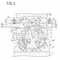
- a member replacement device of the present invention is arranged as described below, as shown in FIG. 1 to FIG. 2 , for example.
- the present invention makes it possible to provide a member replacement device that does not require pressure fluid such as compressed air for operation, or requires only a small amount of pressure fluid even if the pressure fluid is necessary for operation.
- An embodiment of the present invention will be described based on an example of use of a member replacement device, in which the member replacement device is attached to a leading end portion of a robotic arm RA and a tool T that is a clamping object is detachably fixed to the robotic arm RA by the member replacement device.
- the member replacement device for this application is termed a tool changer.
- FIG. 1 and FIG. 2 the following will describe the structure of a member replacement device according to an embodiment of the present invention.
- a housing 1 of the member replacement device is fixed to a leading end portion of a robotic arm RA.
- the housing 1 includes a first housing 2 on the base end side (robotic arm RA side) and a second housing 3 on the leading end side.
- the first housing 2 and the second housing 3 are fixed to each other by multiple bolts (not illustrated).
- the first housing 2 and the second housing 3 may be integrated as long as the assembly of the member replacement device is not obstructed.
- a cylindrical plug member 4 which is integrated with the second housing 3 protrudes toward the leading end side.
- a rod leading end part 5a of an output rod 5 is inserted into a plug member cylindrical hole 4a of the plug member 4, to be movable in an up-down direction (axial direction of the plug member cylindrical hole 4a).
- the axial direction of the output rod 5 is identical with the axial direction of the plug member cylindrical hole 4a.
- a cylindrical hole 6 is formed on the base end side of the second housing 3, and a rod base end part 5b of the output rod 5 is inserted into the cylindrical hole 6 to be movable in the up-down direction.
- the cylindrical hole 6 is larger in diameter than the plug member cylindrical hole 4a.
- a medium-diameter cylindrical hole 7 is formed between the cylindrical hole 6 and the plug member cylindrical hole 4a.
- the cylindrical hole 6, the medium-diameter cylindrical hole 7, and the plug member cylindrical hole 4a have the same axial direction.
- the medium-diameter cylindrical hole 7 is smaller in diameter than the cylindrical hole 6 and larger in diameter than the plug member cylindrical hole 4a.
- the medium-diameter cylindrical hole 7 may be identical with the cylindrical hole 6 in diameter.
- a ball 9 (sphere, rotational body) as an operational member is accommodated to be rotatable.
- a rotational body such as a roller (not illustrated) may be used in place of the ball 9.
- the ball 9 is supported by the recess 8.
- the member replacement device is short in the axial direction and hence the member replacement device is small in size.
- a spring 10 is provided inside the cylindrical hole 6 and the medium-diameter cylindrical hole 7 as a biasing member for biasing the output rod 5 upward (i.e., toward the base end side).
- the spring 10 is a compression coil spring.
- a ring-shaped spring receiver 11, which receives one end of the spring 10, is provided on the outer circumferential surface of the base end portion of the rod base end part 5b. The other end of the spring 10 is received by a stepped portion between the plug member cylindrical hole 4a and the medium-diameter cylindrical hole 7. Upward movement (i.e., movement toward the base end side) of the spring receiver 11 is restricted by a ring-shaped stopper 12 (retaining ring). Therefore, the spring receiver 11 moves upward (toward the base end side) together with the output rod 5.
- the spring receiver 11 has a receiving portion 13 that receives one end of the spring 10, and a cylindrical wall portion 14 that slides in the cylindrical hole 6.
- the length in the axial direction of the cylindrical wall portion 14 is longer than the width in the radial direction of the receiving portion 13. Because the cylindrical wall portion 14 is long in the axial direction, the sliding surface between the cylindrical wall portion 14 and the cylindrical hole 6 is large in area and hence the movement in the axial direction of the output rod 5 is stable.
- through holes 15 are formed to be aligned in the circumferential direction at predetermined intervals.
- a ball 16 engaging ball
- the through hole 15 supports each ball 16 to be movable between an inner position in the radial direction shown in FIG. 1 and an outer position in the radial direction shown in FIG. 2 (i.e., outside position).
- a pressing surface 17 and a retracting groove 18 are formed and vertically aligned, so as to correspond to each ball 16.
- the pressing surface 17 is arranged to increase the width toward the leading end side.
- the ball 16 is moved to the outside position so as to protrude outward in the radial direction as compared to the outer circumferential surface of the plug member 4.
- the retracting groove 18 opposes the ball 16 and the ball 16 becomes insertable, the ball 16 becomes movable inward in the radial direction as compared to the outer circumferential surface of the plug member 4. While in the present embodiment each of the four balls 16 is inserted into each through hole 15, the number of the balls 16 is not limited to four.
- the collet 19 Over a base end portion (base portion) of the circumferential wall of the plug member 4, an annular collet 19 is fitted.
- the collet 19 has a tapered outer circumferential surface 19a that is tapered off toward the leading end, and can be elastically decreased in diameter thanks to a single slit 19b extending in the up-down direction.
- the retaining ring 20 prevents the collet 19 from slipping out from the plug member 4 (i.e., restricts the movement toward the leading end side).
- holes 22 are formed to be aligned in the circumferential direction at predetermined intervals.
- a spring 21 is inserted into each hole 22 as a biasing member for pushing the collet 19 toward the leading end side.
- the spring 21 is a compression coil spring.
- the collet 19 is biased toward the leading end side by the spring 21. On this account, even though the movement toward the leading end side is restricted by the retaining ring 20, the collet 19 is slightly movable in the up-down direction. While in the present embodiment each of the three springs 21 is inserted into each hole 22, the number of the springs 21 is not limited to three.
- a spring of another type such as a plate spring may be used in place of the compression coil spring.
- a guide hole 23 is formed in the first housing 2 to extend in a direction intersecting with the axial direction of the output rod 5.
- the guide hole 23 extends in a direction orthogonal to the axial direction of the output rod 5.
- a cam rod 24 is inserted into the guide hole 23 so as to be movable.
- a cam groove 25 is formed in the outer circumferential surface of the cam rod 24 in order to allow the ball 9 to be fitted therein.
- the cam groove 25 has a cam surface 25a for pressing the ball 9 toward the leading end side.
- the cam surface 25a is a surface that is inclined relative to the axial direction of the cam rod 24.
- a concave surface 26, in which the ball 9 having moved toward the leading end side is fitted, is formed to be connected to the cam surface 25a.
- a rod escaping groove 27 which is shallower than the cam groove 25 is formed in the outer circumferential surface of the cam rod 24 on the same side as the cam groove 25, so as to overlap the cam groove 25.
- the cam groove 25 To ensure a sufficient moving distance in the axial direction of the output rod 5, it is necessary to arrange the cam groove 25 to be sufficiently deep. In this case, there is concern that the base end portion of the output rod 5 may collide with the outer circumferential surface of the cam rod 24. With the arrangement above, it is possible to prevent the output rod 5 from colliding with the cam rod 24, thanks to the rod escaping groove 27. In other words, the arrangement above makes it possible to sufficiently secure the moving distance in the axial direction of output rod 5.
- a guide groove 28 extending in the axial direction of the cam rod 24 is formed in the outer peripheral surface on the opposite side to the cam groove 25 and the rod escaping groove 27.
- a ball 29 is provided in the guide groove 28 as a rotation stopper rotational body.
- the ball 29 is rotatably accommodated in a retaining hole 23a formed in the guide hole 23.
- the retaining hole 23a is provided at the intersection between (i) a virtual extension line C which extends from a center part of the ball 9 (an axial central part of the output rod 5) toward the base end side in the axial direction of the output rod 5 and (ii) the guide hole 23.
- the ball 29 can receive a reaction force that the cam rod 24 receives from the ball 9 while the ball 9 is pressed by the cam surface 25a and is moving toward the leading end side. Furthermore, when the ball 9 has completed its movement toward the leading end side and the ball 9 is fitted in the cam groove 25, the above-described ball 29 can receive the force that the cam rod 24 receives from the ball 9. As a result, it is possible to prevent the guide hole 23 from being damaged due to sliding against the outer circumferential surface of the cam rod 24, and to maintain smooth movement of the cam rod 24 for a long time.
- the above-described reaction force is basically received by the inner circumferential surface of the guide hole 23, which comes into contact with the outer circumferential surface of the cam rod 24 (the outer circumferential surface of a large diameter portion) located to the left of the guide groove 28 in the figure and the inner circumferential surface of the guide hole 23 that comes into contact with a part of the outer circumferential surface of the cam rod 24 in the guide groove 28, where the guide groove 28 is not formed.
- grooves 24a extending in the circumferential direction are formed in the outer circumferential surface of the cam rod 24.
- the number of the grooves 24a is two or more.
- the cam rod 24 has a small diameter portion 24b, and a spring 36 is attached to the outer circumference of the small diameter portion 24b.
- the biasing force of the spring 36 is significantly smaller than the biasing force of the spring 10. The cam rod 24 to which the ball 9 is pressed is not moved solely by the biasing force of the spring 36.
- a release sensor 30 is provided at a side face of the first housing 2 in order to detect whether the cam rod 24 is at a release position shown in FIG. 1 .
- a sensor mounting member 31 is fixed.
- the release sensor 30 is attached.
- the sensor mounting member 31 has a cylindrical hole 31a, and the cam rod 24 is movably inserted into the cylindrical hole 31a.
- the release sensor 30 is a magnetic sensor.
- a ring-shaped magnet 32 is attached to the outer circumferential surface of the cam rod 24 to detect whether the cam rod 24 is at the release position. As the release sensor 30 detects the magnet 32, it is possible to detect that the cam rod 24 is at the release position.
- a lock sensor 34 is attached to a side face of the first housing 2 on the opposite side to the sensor mounting member 31.
- the sensor mounting member 33 has a cylindrical hole 33a, and the cam rod 24 is movably inserted into the cylindrical hole 33a.
- the lock sensor 34 is a magnetic sensor.
- a ring-shaped magnet 35 is attached to the outer circumferential surface of the cam rod 24 to detect whether the cam rod 24 is at the locked position. As the lock sensor 34 detects the magnet 35, it is possible to detect that the cam rod 24 is at the locked position.
- the release sensor 30 and the lock sensor 34 are not limited to magnetic sensors.
- a tool adapter 37 is fixed to the base end of the tool T.
- a recess 38 is formed in the tool adapter 37.
- a ring member 39 is attached to the recess 38, and the ring member 39 is fixed to the tool adapter 37 by bolts (not illustrated).
- the inner circumferential surface of the ring member 39 forms a fitting hole 40, and a plug member 4 is insertable into the fitting hole 40.
- the fitting hole 40 corresponds to a fitting hole formed in the tool T which is an clamping object.
- an engaging portion 41 is formed to be tapered to increase in width toward the bottom of the recess 38.
- a tapered inner circumferential surface 42 is formed to be engaged with a tapered outer circumferential surface 19a of the collet 19.
- the tapered inner circumferential surface 42 is formed to decrease in width toward the bottom of the recess 38.
- the fitting hole 40 is formed in the ring member 39
- the fitting hole 40 may be formed by the inner circumference of the recess 38 of the tool adapter 37.
- the engaging portion 41 and the tapered inner circumferential surface 42 described above may be formed directly in the inner circumference of the recess 38 of the tool adapter 37.
- the fitting hole 40 having the engaging portion 41 and the tapered inner circumferential surface 42 described above may be formed in the tool T.
- the fitting hole 40 When the fitting hole 40 is formed in the tool T, the fitting hole 40 may be formed in the tool T itself, the fitting hole 40 may be formed in the tool adapter 37, or the fitting hole 40 may be formed in the ring member 39 as in the present embodiment.
- the phrase "the fitting hole 40 is formed in the tool T" encompasses not only a case where the fitting hole 40 is formed in the tool T itself but also a case where the fitting hole 40 is formed in a member that is directly fixed to the tool T (e.g., the tool adapter 37) or a member that is indirectly fixed to the tool T (e.g., the ring member 39).
- the above-described member replacement device operates as follows.
- the ball 9 is fitted in the concave surface 26 formed in the cam rod 24 and is pressed into the cylindrical hole 6 of the second housing 3 as compared to the locked state shown in FIG. 2 . Due to this, a state in which the ball 9 presses and lowers the output rod 5 toward the leading end side against the biasing force of the spring 10 has been established. As the output rod 5 descends, the ball 16 of the plug member 4 is movable to the retracting position inside the retracting groove 18. The robotic arm RA is operated so that the leading end portion of the robotic arm RA to which the member replacement device having members such as the output rod 5 is attached is positioned above the ring member 39 that is fixed to the tool T through the tool adapter 37.
- the leading end portion of the robotic arm RA is lowered and the plug member 4 is inserted into the fitting hole 40 of the ring member 39.
- the tapered inner circumferential surface 42 of the fitting hole 40 makes contact with the tapered outer circumferential surface 19a of the collet 19 in an enlarged diameter state, and a slight gap is formed between the upper surface 3a (seating surface) of the second housing 3 and the ring member 39.
- an end portion 24c of the cam rod 24 protruding from the sensor mounting member 31 is brought into contact with a stationary object (not illustrated) by, for example, moving the leading end portion of the robotic arm RA in the horizontal direction, so that the leading end portion 24c of the cam rod 24 is pressed into the guide hole 23 on account of a reaction force from the object.
- the end portion 24c of the cam rod 24 is pressed into the guide hole 23
- the ball 9 comes off from the concave surface 26 formed in the cam rod 24.
- the ball 9 is then pressed by the biasing force of the spring 10, and moves along the cam surface 25a and enters the cam groove 25.
- a pressing portion 18a constituting part of the retracting groove 18 formed in the output rod 5 presses the ball 16 of the plug member 4 to a protruding position on the outer side in the radial direction. Subsequently, the pressing surface 17 of the output rod 5 presses the engaging portion 41 of the tool T (ring member 39) upward through the ball 16. As a result, the collet 19 decreases in diameter and slightly ascends together with the tool T. Consequently, the ring member 39 is received by the upper surface 3a of the second housing 3, and the tool T is firmly fixed to the leading end portion of the robotic arm RA through the member replacement device. The member replacement device is switched from the released state shown in FIG. 1 to the locked state shown in FIG. 2 .
- the robotic arm Ra is operated so that an end portion 24d of the cam rod 24 protruding from the sensor mounting member 33 is brought into contact with a stationary object (not illustrated) and the leading end portion 24d of the cam rod 24 is pressed into the guide hole 23 on account of a reaction force from the object.
- the cam surface 25a formed on the cam rod 24 presses the ball 9, and the ball 9 moves along the cam surface 25a and climbs on the concave surface 26.
- the ball 9 presses the output rod 5 toward the leading end side against the biasing force of the spring 10, with the result that the output rod 5 descends.
- the retracting groove 18 formed in the output rod 5 is positioned to oppose the ball 16 of the plug member 4, and the ball 16 becomes movable into the retracting groove 18 (i.e., inward in the radial direction of the output rod 5).
- the tool T ring member 39
- the friction force between the ball 9 and the cam surface 25a is reduced by the rotation of the ball 9.
- the force of pressing the cylindrical wall portion 14 of the spring receiver 11 onto the inner circumferential surface of the cylindrical hole 6 by the ball 9 through the output rod 5 is reduced, and hence partial sliding wear or damage of the outer circumferential surface of the cylindrical wall portion 14 and the inner circumferential surface of the cylindrical hole 6 is reduced.
- partial wear or damage occurring between the inner circumferential surface of the plug member cylindrical hole 4a of the plug member 4 and the outer circumferential surface of the output rod 5 is also reduced. On this account, it is possible to smoothly move the output rod 5 toward the leading end side.
- the member replacement device of the present embodiment does not have chambers such as the clamping chamber and the unclamping chamber of the known clamping device, to which and from which pressure fluid is supplied and discharged each time the device is driven.
- the output rod 5 is pressed by the ball 9 and moved toward the leading end side.
- the output rod 5 is driven to move by the spring 10.
- the member replacement device can therefore be driven without requiring compressed fluid such as compressed air. Instead of moving the cam rod 24 by hitting it onto an object, the cam rod 24 may be moved by being pushed by a human hand.
- the spring 10 is provided inside the cylindrical hole 6 and the medium-diameter cylindrical hole 7, and the spring 10 is arranged to press and move the output rod 5 toward the base end side.
- the space inside the cylindrical hole 6 and the medium-diameter cylindrical hole 7 may be arranged to function as a pressurized gas chamber, and the output rod 5 may be pressed and moved toward the base end side by the gas pressure of the pressurized gas chamber.
- the pressurized gas chamber refers to a chamber filled with pressurized gas.
- the pressurized gas chamber is sealed against the outside to prevent the pressurized gas from leaking out.
- the pressurized gas with which the pressurized gas chamber is filled is the biasing member configured to press and move the output rod 5 toward the base end side, in place of the spring 10. Examples of the pressurized gas include compressed air and compressed nitrogen gas.
- the pressurized gas chamber is sealed to prevent the pressurized gas from leaking to the outside, as described above.
- a small amount of pressurized gas may leak out from the pressurized gas chamber.
- the member replacement device is preferably arranged so that an amount of the compressed air equal to the amount leaking out from the pressurized gas chamber is supplied to the pressurized gas chamber.
- pressurized gas is supplied only by the amount leaking out from the pressurized gas chamber.
- the use amount of the compressed air is extremely small. Therefore, while a facility for supplying the pressurized gas such as an air compressor is still required, the facility may be very small in size.
- the posture of the member replacement device may be different from the vertical posture described above, and may be turned upside down, may be lateral, or may be inclined.
- the member replacement device may be fixed to a movable portion of the conveying machine, or to a table as a fixing base.
- the clamping object may be, for example, a jig, a machining object, or a pallet.
- Both the release sensor 30 and the lock sensor 34 or either the release sensor 30 or the lock sensor 34 may be omitted.
Landscapes
- Engineering & Computer Science (AREA)
- Mechanical Engineering (AREA)
- Robotics (AREA)
- Jigs For Machine Tools (AREA)
- Manipulator (AREA)
- Mutual Connection Of Rods And Tubes (AREA)
- Pivots And Pivotal Connections (AREA)
- Push-Button Switches (AREA)
- Preventing Unauthorised Actuation Of Valves (AREA)
Applications Claiming Priority (2)
| Application Number | Priority Date | Filing Date | Title |
|---|---|---|---|
| JP2022154147A JP2024048226A (ja) | 2022-09-27 | 2022-09-27 | 部材交換装置 |
| PCT/JP2023/031055 WO2024070395A1 (ja) | 2022-09-27 | 2023-08-28 | 部材交換装置 |
Publications (2)
| Publication Number | Publication Date |
|---|---|
| EP4545247A1 true EP4545247A1 (de) | 2025-04-30 |
| EP4545247A4 EP4545247A4 (de) | 2025-10-15 |
Family
ID=90477096
Family Applications (1)
| Application Number | Title | Priority Date | Filing Date |
|---|---|---|---|
| EP23871636.9A Pending EP4545247A4 (de) | 2022-09-27 | 2023-08-28 | Vorrichtung zum ersetzen eines elements |
Country Status (7)
| Country | Link |
|---|---|
| US (1) | US20260048482A1 (de) |
| EP (1) | EP4545247A4 (de) |
| JP (1) | JP2024048226A (de) |
| KR (1) | KR20250041163A (de) |
| CN (1) | CN119968245A (de) |
| TW (1) | TWI877771B (de) |
| WO (1) | WO2024070395A1 (de) |
Families Citing this family (3)
| Publication number | Priority date | Publication date | Assignee | Title |
|---|---|---|---|---|
| US12134157B2 (en) * | 2019-10-28 | 2024-11-05 | Kosmek Ltd. | Clamping apparatus |
| WO2022045990A1 (en) * | 2020-08-25 | 2022-03-03 | Cnc İleri̇ Teknoloji̇ Mühendi̇sli̇k Sanayi̇ Ve Ti̇caret Li̇mi̇ted Şi̇rketi̇ | System for hold, clamp and position objects |
| WO2025239194A1 (ja) * | 2024-05-17 | 2025-11-20 | 株式会社コスメック | クランプシステム |
Family Cites Families (12)
| Publication number | Priority date | Publication date | Assignee | Title |
|---|---|---|---|---|
| US5015003A (en) * | 1988-08-03 | 1991-05-14 | Kennametal Inc. | Top jaw assembly with replaceable work holding pads |
| JP2513536Y2 (ja) * | 1990-06-22 | 1996-10-09 | スズキ株式会社 | 製品取出機のチャック治具取付構造 |
| EP0559424B1 (de) * | 1992-03-04 | 1997-05-14 | Kuroda Seiko Company Limited | Werkzeug-Ein- und Ausspannvorrichtung |
| JP6353796B2 (ja) * | 2015-02-27 | 2018-07-04 | 株式会社コスメック | 出力装置および出力システム |
| JP6604531B2 (ja) * | 2015-03-26 | 2019-11-13 | ニッタ株式会社 | 雄型部材及び工具交換装置 |
| ITUB20155846A1 (it) * | 2015-11-24 | 2017-05-24 | Gimatic S R L | Dispositivo cambia utensile |
| JP7127836B2 (ja) * | 2019-02-13 | 2022-08-30 | 株式会社コスメック | 工具交換装置 |
| JP6776385B2 (ja) * | 2019-02-13 | 2020-10-28 | 日本金銭機械株式会社 | ロボットハンド付きロボットアームの制御方法、制御装置および制御システム |
| US12134157B2 (en) * | 2019-10-28 | 2024-11-05 | Kosmek Ltd. | Clamping apparatus |
| KR200498307Y1 (ko) | 2020-03-06 | 2024-09-02 | 가부시키가이샤 코스멕 | 클램프 장치 |
| JP7159506B2 (ja) * | 2020-07-01 | 2022-10-24 | ビー・エル・オートテック株式会社 | ツール交換装置 |
| JP7016928B1 (ja) * | 2020-09-14 | 2022-02-07 | 株式会社スギノマシン | 立形工作機械及び工具交換方法 |
-
2022
- 2022-09-27 JP JP2022154147A patent/JP2024048226A/ja active Pending
-
2023
- 2023-08-28 KR KR1020257006154A patent/KR20250041163A/ko active Pending
- 2023-08-28 EP EP23871636.9A patent/EP4545247A4/de active Pending
- 2023-08-28 WO PCT/JP2023/031055 patent/WO2024070395A1/ja not_active Ceased
- 2023-08-28 CN CN202380068801.9A patent/CN119968245A/zh active Pending
- 2023-08-28 US US19/101,605 patent/US20260048482A1/en active Pending
- 2023-09-07 TW TW112134019A patent/TWI877771B/zh active
Also Published As
| Publication number | Publication date |
|---|---|
| US20260048482A1 (en) | 2026-02-19 |
| TW202421330A (zh) | 2024-06-01 |
| CN119968245A (zh) | 2025-05-09 |
| TWI877771B (zh) | 2025-03-21 |
| JP2024048226A (ja) | 2024-04-08 |
| KR20250041163A (ko) | 2025-03-25 |
| WO2024070395A1 (ja) | 2024-04-04 |
| EP4545247A4 (de) | 2025-10-15 |
Similar Documents
| Publication | Publication Date | Title |
|---|---|---|
| EP4545247A1 (de) | Vorrichtung zum ersetzen eines elements | |
| KR100637276B1 (ko) | 데이텀기능을 부착한 클램프장치 | |
| KR102175508B1 (ko) | 클램프 장치 | |
| JP2002361533A (ja) | データム機能付きクランプ装置 | |
| EP2489464A1 (de) | Spannvorrichtung | |
| KR20140105589A (ko) | 배력 기구 부설 실린더 장치 | |
| US7165763B2 (en) | Positioning device | |
| US12134157B2 (en) | Clamping apparatus | |
| EP3409414B1 (de) | Spannvorrichtung mit hebefunktion | |
| KR100411829B1 (ko) | 워크 서포트 | |
| EP4534239A1 (de) | Klemmvorrichtung | |
| EP3895840A1 (de) | Spannvorrichtung | |
| JP2017154246A5 (de) | ||
| US11471989B2 (en) | Suction positioning structure and suction positioning device | |
| JP3527738B2 (ja) | データム機能付きクランプ装置及びその装置を備えたクランプシステム | |
| JP2024067629A (ja) | クランプシステム | |
| JP3459414B2 (ja) | データム機能付きクランプ装置 | |
| JP2024086379A (ja) | クランプシステム | |
| EP4603224A1 (de) | Positioniervorrichtung | |
| WO2025239194A1 (ja) | クランプシステム | |
| JP2024062652A (ja) | クランプ装置 |
Legal Events
| Date | Code | Title | Description |
|---|---|---|---|
| STAA | Information on the status of an ep patent application or granted ep patent |
Free format text: STATUS: THE INTERNATIONAL PUBLICATION HAS BEEN MADE |
|
| PUAI | Public reference made under article 153(3) epc to a published international application that has entered the european phase |
Free format text: ORIGINAL CODE: 0009012 |
|
| STAA | Information on the status of an ep patent application or granted ep patent |
Free format text: STATUS: REQUEST FOR EXAMINATION WAS MADE |
|
| 17P | Request for examination filed |
Effective date: 20250122 |
|
| AK | Designated contracting states |
Kind code of ref document: A1 Designated state(s): AL AT BE BG CH CY CZ DE DK EE ES FI FR GB GR HR HU IE IS IT LI LT LU LV MC ME MK MT NL NO PL PT RO RS SE SI SK SM TR |
|
| A4 | Supplementary search report drawn up and despatched |
Effective date: 20250911 |
|
| RIC1 | Information provided on ipc code assigned before grant |
Ipc: B23Q 3/12 20060101AFI20250905BHEP Ipc: B23B 31/06 20060101ALI20250905BHEP Ipc: B23B 31/107 20060101ALI20250905BHEP Ipc: B23Q 3/00 20060101ALI20250905BHEP Ipc: B25J 15/04 20060101ALI20250905BHEP Ipc: B25J 19/00 20060101ALI20250905BHEP Ipc: B25B 5/02 20060101ALI20250905BHEP Ipc: B23Q 1/00 20060101ALI20250905BHEP |
|
| P01 | Opt-out of the competence of the unified patent court (upc) registered |
Free format text: CASE NUMBER: UPC_APP_0010843_4545247/2025 Effective date: 20251023 |
|
| DAV | Request for validation of the european patent (deleted) | ||
| DAX | Request for extension of the european patent (deleted) | ||
| GRAP | Despatch of communication of intention to grant a patent |
Free format text: ORIGINAL CODE: EPIDOSNIGR1 |
|
| STAA | Information on the status of an ep patent application or granted ep patent |
Free format text: STATUS: GRANT OF PATENT IS INTENDED |
|
| RIC1 | Information provided on ipc code assigned before grant |
Ipc: B23Q 3/12 20060101AFI20260129BHEP Ipc: B23B 31/06 20060101ALI20260129BHEP Ipc: B23B 31/107 20060101ALI20260129BHEP Ipc: B23Q 3/00 20060101ALI20260129BHEP Ipc: B25J 15/04 20060101ALI20260129BHEP Ipc: B25J 19/00 20060101ALI20260129BHEP Ipc: B25B 5/02 20060101ALI20260129BHEP Ipc: B23Q 1/00 20060101ALI20260129BHEP |
|
| INTG | Intention to grant announced |
Effective date: 20260216 |
|
| GRAS | Grant fee paid |
Free format text: ORIGINAL CODE: EPIDOSNIGR3 |