EP4545256A1 - Système de robot, robot et procédé de commande de système de robot - Google Patents
Système de robot, robot et procédé de commande de système de robot Download PDFInfo
- Publication number
- EP4545256A1 EP4545256A1 EP23849804.2A EP23849804A EP4545256A1 EP 4545256 A1 EP4545256 A1 EP 4545256A1 EP 23849804 A EP23849804 A EP 23849804A EP 4545256 A1 EP4545256 A1 EP 4545256A1
- Authority
- EP
- European Patent Office
- Prior art keywords
- imager
- workpiece
- robot
- hand
- workpieces
- Prior art date
- Legal status (The legal status is an assumption and is not a legal conclusion. Google has not performed a legal analysis and makes no representation as to the accuracy of the status listed.)
- Pending
Links
Images


Classifications
-
- B—PERFORMING OPERATIONS; TRANSPORTING
- B25—HAND TOOLS; PORTABLE POWER-DRIVEN TOOLS; MANIPULATORS
- B25J—MANIPULATORS; CHAMBERS PROVIDED WITH MANIPULATION DEVICES
- B25J15/00—Gripping heads and other end effectors
- B25J15/06—Gripping heads and other end effectors with vacuum or magnetic holding means
- B25J15/0616—Gripping heads and other end effectors with vacuum or magnetic holding means with vacuum
-
- B—PERFORMING OPERATIONS; TRANSPORTING
- B25—HAND TOOLS; PORTABLE POWER-DRIVEN TOOLS; MANIPULATORS
- B25J—MANIPULATORS; CHAMBERS PROVIDED WITH MANIPULATION DEVICES
- B25J9/00—Program-controlled manipulators
- B25J9/16—Program controls
- B25J9/1694—Program controls characterised by use of sensors other than normal servo-feedback from position, speed or acceleration sensors, perception control, multi-sensor controlled systems, sensor fusion
- B25J9/1697—Vision controlled systems
-
- B—PERFORMING OPERATIONS; TRANSPORTING
- B25—HAND TOOLS; PORTABLE POWER-DRIVEN TOOLS; MANIPULATORS
- B25J—MANIPULATORS; CHAMBERS PROVIDED WITH MANIPULATION DEVICES
- B25J15/00—Gripping heads and other end effectors
- B25J15/0052—Gripping heads and other end effectors multiple gripper units or multiple end effectors
-
- B—PERFORMING OPERATIONS; TRANSPORTING
- B25—HAND TOOLS; PORTABLE POWER-DRIVEN TOOLS; MANIPULATORS
- B25J—MANIPULATORS; CHAMBERS PROVIDED WITH MANIPULATION DEVICES
- B25J19/00—Accessories fitted to manipulators, e.g. for monitoring, for viewing; Safety devices combined with or specially adapted for use in connection with manipulators
- B25J19/02—Sensing devices
- B25J19/021—Optical sensing devices
- B25J19/023—Optical sensing devices including video camera means
-
- B—PERFORMING OPERATIONS; TRANSPORTING
- B25—HAND TOOLS; PORTABLE POWER-DRIVEN TOOLS; MANIPULATORS
- B25J—MANIPULATORS; CHAMBERS PROVIDED WITH MANIPULATION DEVICES
- B25J5/00—Manipulators mounted on wheels or on carriages
- B25J5/007—Manipulators mounted on wheels or on carriages mounted on wheels
-
- B—PERFORMING OPERATIONS; TRANSPORTING
- B25—HAND TOOLS; PORTABLE POWER-DRIVEN TOOLS; MANIPULATORS
- B25J—MANIPULATORS; CHAMBERS PROVIDED WITH MANIPULATION DEVICES
- B25J9/00—Program-controlled manipulators
- B25J9/0093—Program-controlled manipulators co-operating with conveyor means
-
- B—PERFORMING OPERATIONS; TRANSPORTING
- B65—CONVEYING; PACKING; STORING; HANDLING THIN OR FILAMENTARY MATERIAL
- B65G—TRANSPORT OR STORAGE DEVICES, e.g. CONVEYORS FOR LOADING OR TIPPING, SHOP CONVEYOR SYSTEMS OR PNEUMATIC TUBE CONVEYORS
- B65G61/00—Use of pick-up or transfer devices or of manipulators for stacking or de-stacking articles not otherwise provided for
-
- B—PERFORMING OPERATIONS; TRANSPORTING
- B65—CONVEYING; PACKING; STORING; HANDLING THIN OR FILAMENTARY MATERIAL
- B65G—TRANSPORT OR STORAGE DEVICES, e.g. CONVEYORS FOR LOADING OR TIPPING, SHOP CONVEYOR SYSTEMS OR PNEUMATIC TUBE CONVEYORS
- B65G67/00—Loading or unloading vehicles
- B65G67/02—Loading or unloading land vehicles
-
- B—PERFORMING OPERATIONS; TRANSPORTING
- B65—CONVEYING; PACKING; STORING; HANDLING THIN OR FILAMENTARY MATERIAL
- B65G—TRANSPORT OR STORAGE DEVICES, e.g. CONVEYORS FOR LOADING OR TIPPING, SHOP CONVEYOR SYSTEMS OR PNEUMATIC TUBE CONVEYORS
- B65G2203/00—Indexing code relating to control or detection of the articles or the load carriers during conveying
- B65G2203/02—Control or detection
- B65G2203/0208—Control or detection relating to the transported articles
- B65G2203/0233—Position of the article
-
- B—PERFORMING OPERATIONS; TRANSPORTING
- B65—CONVEYING; PACKING; STORING; HANDLING THIN OR FILAMENTARY MATERIAL
- B65G—TRANSPORT OR STORAGE DEVICES, e.g. CONVEYORS FOR LOADING OR TIPPING, SHOP CONVEYOR SYSTEMS OR PNEUMATIC TUBE CONVEYORS
- B65G2203/00—Indexing code relating to control or detection of the articles or the load carriers during conveying
- B65G2203/04—Detection means
- B65G2203/041—Camera
Definitions
- the present disclosure relates to a robot system, a robot, and a method for controlling a robot system.
- U.S. Patent No. 10,124,489 discloses a robot system that uses a hand to hold a desired workpiece from a plurality of stacked box-shaped workpieces and move the held workpiece to a predetermined location.
- the plurality of stacked box-shaped workpieces are imaged by an imager, and the robot system selects a workpiece to be held by the hand from among the plurality of stacked box-shaped workpieces based on the image captured by the imager.
- the hand then holds the selected workpiece.
- the workpiece held by the hand is moved to the predetermined location.
- the imager is fixed at a location spaced apart from a robot arm.
- the imager may be arranged on the robot arm. Furthermore, imaging of the plurality of stacked box-shaped workpieces by the imager and moving the workpiece with the hand are repeatedly performed.
- Patent Document 1 U.S. Patent No. 10,124,489
- the imager arranged on the robot arm faces a direction different from a direction in which the plurality of stacked box-shaped workpieces are arranged. Therefore, when the plurality of stacked box-shaped workpieces are next imaged by the imager, it is necessary to move the robot arm such that the imager faces the plurality of stacked box-shaped workpieces, and to stop the robot arm once to image the plurality of box-shaped workpieces with the imager. In other words, it is necessary to stop the robot arm to image the workpieces with the imager during a period of time other than a period of time during which the operation to place the workpiece held by the hand at the predetermined location is performed. Therefore, the cycle time for repeated operations to image the workpieces with the imager and move the workpiece with the hand disadvantageously increases.
- the present disclosure is intended to solve the above problems.
- the present disclosure aims to provide a robot system, a robot, and a method for controlling a robot system in which even when a placement location of a workpiece is changed, it is not necessary to change the fixed location of an imager, and the cycle time for repeated operations to image a workpiece with the imager and move the workpiece with a hand can be decreased.
- a robot system includes a robot main body including a base and a robot arm including a proximal end attached to the base so as to rotate around a first rotation axis, and a distal end to which a hand operable to hold a workpiece is attached, an imager on the robot main body rotatable in accordance with movement of the robot main body, and including an imaging area to be changed separately from a change in the imaging area caused by rotation of the robot arm around the first rotation axis, and a controller.
- the controller is configured or programmed to control the imaging area of the imager such that the workpiece to be held next is imaged during operation to rotate the robot arm around the first rotation axis to place the workpiece held by the hand at a predetermined placement location.
- an imager on the robot main body includes a case in which the imager is directly on the robot main body, and a case in which the imager is on the robot main body via some kind of member.
- the imager is on the robot main body, is rotatable in accordance with movement of the robot main body, and includes the imaging area to be changed separately from the change in the imaging area caused by the rotation around the first rotation axis, and the controller is configured or programmed to control the imaging area of the imager such that the workpiece to be held next is imaged during the operation to rotate the robot arm around the first rotation axis to place the workpiece held by the hand at the predetermined placement location. Accordingly, the imager is on the robot main body, and thus even when the placement location of the workpiece is changed, the imager can be moved by moving the robot main body such that the workpiece is positioned within the field of view of the imager.
- the imaging area of the imager is changed separately from the change in the imaging area caused by the rotation around the first rotation axis, and thus the workpiece to be held next can be imaged during the operation to rotate the robot arm around the first rotation axis to place the workpiece held by the hand at the predetermined placement location. Therefore, the operation to place the workpiece at the predetermined placement location and imaging of the workpiece to be held next can be performed simultaneously.
- the cycle time for repeated operations to image the workpiece with the imager and move the workpiece with the hand can be decreased.
- the cycle time for the repeated operations to image the workpiece with the imager and move the workpiece with the hand can be decreased.
- a robot includes a robot main body including a base and a robot arm including a proximal end attached to the base so as to rotate around a predetermined rotation axis, and a distal end to which a hand operable to hold a workpiece is attached, an imager on the robot main body rotatable in accordance with movement of the robot main body, and including an imaging area to be changed separately from a change in the imaging area caused by rotation of the robot arm around the predetermined rotation axis, and a controller.
- the controller is configured or programmed to control the imaging area of the imager such that the workpiece to be held next is imaged during operation to rotate the robot arm around the predetermined rotation axis to place the workpiece held by the hand at a predetermined placement location.
- the imaging area of the imager is changed separately from the change in the imaging area caused by the rotation around the first rotation axis, and thus the workpiece to be held next can be imaged during the operation to rotate the robot arm around the first rotation axis to place the workpiece held by the hand at the predetermined placement location. Therefore, the operation to place the workpiece at the predetermined placement location and imaging of the workpiece to be held next can be performed simultaneously.
- the cycle time for repeated operations to image the workpiece with the imager and move the workpiece with the hand can be decreased.
- a method for controlling a robot system is a method for controlling a robot system including a robot main body including a base and a robot arm including a proximal end attached to the base so as to rotate around a predetermined rotation axis, and a distal end to which a hand operable to hold a workpiece is attached, and an imager on the robot main body rotatable in accordance with movement of the robot main body and to image the workpiece, and includes causing the hand to hold the workpiece, rotating the robot arm around the predetermined axis while the workpiece is held by the hand to place the workpiece at a predetermined placement location, and controlling an imaging area of the imager separately from a change in the imaging area caused by rotation around the predetermined rotation axis such that the workpiece to be held next is imaged with the imager, during operation to place the workpiece held by the hand at the predetermined placement location.
- the method for controlling the robot system includes rotating the robot arm around the predetermined axis while the workpiece is held by the hand to place the workpiece at the predetermined placement location, and controlling the imaging area of the imager separately from the change in the imaging area caused by rotation around the predetermined rotation axis such that the workpiece to be held next is imaged with the imager, during the operation to place the workpiece held by the hand at the predetermined placement location. Accordingly, the imager is on the robot main body, and thus even when the placement location of the workpiece is changed, the imager can be moved by moving the robot main body such that the workpiece is positioned within the field of view of the imager.
- the imaging area of the imager is changed separately from the change in the imaging area caused by the rotation around the first rotation axis, and thus the workpiece to be held next can be imaged during the operation to rotate the robot arm around the first rotation axis to place the workpiece held by the hand at the predetermined placement location. Therefore, the operation to place the workpiece at the predetermined placement location and imaging of the workpiece to be held next can be performed simultaneously.
- the cycle time for repeated operations to image the workpiece with the imager and move the workpiece with the hand can be decreased.
- the method for controlling the robot system in which even when the placement location of the workpiece is changed, it is not necessary to change the fixed location of the imager, and the cycle time for the repeated operations to image the workpiece with the imager and move the workpiece with the hand can be decreased.
- the cycle time for the repeated operations to image the workpiece with the imager and move the workpiece with the hand can be decreased.
- an upward-downward direction is defined as a Z direction.
- a direction perpendicular to the Z direction is defined as an X direction.
- a direction perpendicular to the Z direction and the X direction is defined as a Y direction.
- the robot system 100 holds a plurality of workpieces 2 placed in a cargo compartment of a truck 1, and places the workpieces 2 on a conveyor 3.
- the workpieces 2 are box-shaped.
- the workpieces 2 are cardboard boxes, for example.
- the workpieces 2 are stacked.
- the conveyor 3 is an extendable conveyor 3, for example.
- the conveyor 3 is an example of a predetermined placement location.
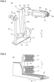
- the robot system 100 includes a robot 20 including a cart 10 and a robot arm 21, a hand 30, an imager 40, a mounting member 50 shown in FIG. 3 , an imager movement mechanism 60, and a controller 70.
- the conveyor 3 may be included in the robot system 100.
- the cart 10 is an example of a base.
- the robot 20 is an example of a robot main body.
- the robot arm 21 is placed on the cart 10.
- the cart 10 moves the robot arm 21.
- the cart 10 is an automated guided vehicle (AGV), for example.
- the cart 10 includes a drive such as a motor, and wheels 11 that are rotated by the drive.
- the drive is controlled by the controller 70 to move the cart 10.
- the cart 10 automatically moves the robot arm 21 to the vicinity of the truck 1.
- a proximal end of the robot arm 21 is attached to the cart 10 so as to rotate around a JT1 axis with respect to the cart 10.
- the hand 30 shown in FIG. 4 that holds a workpiece 2 is attached to a distal end of the robot arm 21.
- the JT1 axis is a rotation axis along the Z direction.
- the robot arm 21 is an articulated robot arm.
- the robot arm 21 is a vertical articulated robot arm.
- the robot arm 21 includes an arm 22a connected to the cart 10, and arms 22b, 22c, 22d, and 22e arranged between the arm 22a and the hand 30.
- the arms 22a, 22b, 22c, 22d, and 22e are connected to each other by joints 23.
- six joints 23 are arranged. That is, the robot arm 21 includes a 6-axis vertical articulated robot.
- the six joints 23 rotate around the JT1 axis, a JT2 axis, a JT3 axis, a JT4 axis, a JT5 axis, and a JT6 axis, respectively.
- a drive such as a motor and a position detector such as an encoder are arranged in each of the plurality of joints 23.
- the drive is controlled by the controller 70 such that movement of the robot arm 21 is controlled.
- the arm 22a is an example of a proximal end arm.
- the arms 22b, 22c, 22d, and 22e are examples of a distal end arm.
- the JT1 axis is an example of a first rotation axis or a predetermined rotation axis.
- the hand 30 includes suckers 31 that suction the box-shaped workpiece 2.
- a plurality of suckers 31 are arranged.
- the hand 30 includes a movement mechanism 32 that moves the suckers 31 linearly along an A direction and a movement mechanism 33 that moves the suckers 31 linearly along a B direction.
- the movement mechanisms 32 and 33 include drives such as motors.
- the drives are controlled by the controller 70 such that the suckers 31 are moved by the movement mechanisms 32 and 33.
- the suckers 31 are suction pads, for example.
- the imager 40 is arranged on the robot 20.
- the imager 40 is arranged on the robot arm 21.
- the imager 40 rotates in accordance with movement of the robot 20. Specifically, the imager 40 rotates together with rotation of the robot arm 21 around the JT1 axis, and an imaging area is changed separately from a change in the imaging area caused by the rotation around the JT1 axis.
- the imaging area of the imager 40 is changed by at least one of changing an imaging direction by moving the imager 40 separately from the change in the imaging area caused by the rotation around the JT1 axis and changing the zoom magnification of the imager 40.
- the imaging area of the imager 40 is changed by changing the imaging direction by moving the imager 40 separately from the change in the imaging area caused by the rotation around the JT1 axis.
- the imaging area of the imager 40 refers to a range imaged by the imager 40.
- the imaging area is an area including all of the plurality of stacked box-shaped workpieces 2, or an area including only a portion of the plurality of stacked box-shaped workpieces 2.
- the imager 40 is a three-dimensional camera. Alternatively, the imager 40 may be a two-dimensional camera.
- the imager 40 does not have a pan function, a tilt function, or a zoom function.
- the imager 40 rotates together with rotation of the robot arm 21 around the JT1 axis, and thus the amount of rotation of the imager 40 itself for imaging the workpieces 2 can be decreased as compared with a case in which the imager 40 does not rotate together with rotation of the robot arm 21 around the JT1 axis.
- the imager 40 rotates together with rotation of the robot arm 21 around the JT1 axis, and thus interference between the imager 40 and the robot arm 21 can be reduced.
- the imager 40 is attached to the arm 22a. Specifically, the imager 40 is attached to the arm 22a via the mounting member 50.
- the mounting member 50 rotates together with the arm 22a and is provided to attach the imager 40 to the arm 22a.
- the mounting member 50 is attached to the arm 22a.
- the mounting member 50 rotates together with the arm 22a around the JT1 axis.
- the mounting member 50 has a plate shape that is arranged along an XY plane, which is a horizontal plane.
- the imager movement mechanism 60 is attached to the mounting member 50.
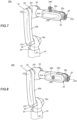
- the imager movement mechanism 60 performs at least one of lifting the imager 40 up and down and rotating the imager 40 around an AX axis different from the JT1 axis.
- the imager 40 is moved by the imager movement mechanism 60 such that the imaging area of the imager 40 is changed.
- the imager movement mechanism 60 includes a pillar 61 and a lifter 62.
- the pillar 61 is attached to the mounting member 50 along the Z direction.
- the pillar 61 is attached to the mounting member 50 so as to be horizontally spaced apart from the robot arm 21.
- the lifter 62 rises and falls along the pillar 61.
- the imager 40 is attached to the lifter 62.
- the imager 40 rises and falls together with the lifter 62 rising and falling.
- the lifter 62 rotates around the AX axis.
- the imager 40 rotates together with rotation of the lifter 62 around the AX axis.
- the AX axis is the central axis of the pillar 61.
- a drive such as a motor is arranged in the lifter 62. The drive is controlled by the controller 70 such that the lifter 62 rises, falls, and rotates.
- the pillar 61 is attached to the mounting member 50 so as to be horizontally spaced apart from the robot arm 21, and thus the imager 40 is horizontally spaced apart from the robot arm 21.
- the AX axis is an example of a second rotation axis.
- the controller 70 controls the imaging area of the imager 40 such that a workpiece 2 to be held next is imaged during the operation to rotate the robot arm 21 around the JT1 axis to place the workpiece 2 held by the hand 30 on the conveyor 3.
- the controller 70 is arranged in the cart 10, for example. Alternatively, the controller 70 may be arranged in a location other than the cart 10.
- the controller 70 controls the operations of the cart 10, the robot arm 21, the hand 30, the imager 40, and the imager movement mechanism 60.
- One controller 70 may control all of the operations of the robot arm 21, the hand 30, the imager 40, and the imager movement mechanism 60, or the operations of the robot arm 21, the hand 30, the imager 40, and the imager movement mechanism 60 may be controlled by cooperation between a plurality of controllers 70.
- the expression “during the operation to place the workpiece 2 on the conveyor 3" refers to a period of time from when rotation of the robot arm 21 around the JT1 axis is stopped until when the workpiece 2 held by the hand 30 is placed on the conveyor 3 and then rotation of the robot arm 21 around the JT1 axis is started again.
- the operation of the robot system 100 is specifically described below. The following operation is controlled by the controller 70.
- step S1 the cart 10 moves such that the robot arm 21 moves to the vicinity of the truck 1.
- the conveyor 3 moves to the vicinity of the truck 1 together with the cart 10.
- the cart 10 and the conveyor 3 are connected to each other, and thus the conveyor 3 moves together with the cart 10.
- the cart 10 and the conveyor 3 may not be connected to each other. In such a case, the conveyor 3 is placed in the vicinity of the truck 1 in advance.
- step S2 the robot arm 21 is rotated around the JT1 axis such that the imager 40 directly faces the plurality of workpieces 2 stacked on the truck 1.
- the imager 40 images the plurality of workpieces 2 stacked on the truck 1.
- the controller 70 controls movement of the cart 10, and lifting, lowering, and rotation of the lifter 62 of the imager movement mechanism 60 such that the imager 40 can image all of the plurality of workpieces 2 stacked on the truck 1.
- the robot system according to item 5 wherein the imager has at least one of a pan function, a tilt function, and a zoom function.
- the robot system according to any one of items 1 to 9, wherein the base includes a cart to move the robot arm.
- a robot comprising:
- a method for controlling a robot system comprising a robot main body including a base and a robot arm including a proximal end attached to the base so as to rotate around a predetermined rotation axis, and a distal end to which a hand operable to hold a workpiece is attached, and an imager on the robot main body rotatable in accordance with movement of the robot main body and to image the workpiece, the method comprising:
Landscapes
- Engineering & Computer Science (AREA)
- Mechanical Engineering (AREA)
- Robotics (AREA)
- Aviation & Aerospace Engineering (AREA)
- Multimedia (AREA)
- Manipulator (AREA)
Applications Claiming Priority (2)
| Application Number | Priority Date | Filing Date | Title |
|---|---|---|---|
| JP2022123471A JP2024020916A (ja) | 2022-08-02 | 2022-08-02 | ロボットシステム、ロボットおよびロボットシステムの制御方法 |
| PCT/JP2023/024144 WO2024029245A1 (fr) | 2022-08-02 | 2023-06-29 | Système de robot, robot et procédé de commande de système de robot |
Publications (2)
| Publication Number | Publication Date |
|---|---|
| EP4545256A1 true EP4545256A1 (fr) | 2025-04-30 |
| EP4545256A4 EP4545256A4 (fr) | 2025-10-22 |
Family
ID=89848790
Family Applications (1)
| Application Number | Title | Priority Date | Filing Date |
|---|---|---|---|
| EP23849804.2A Pending EP4545256A4 (fr) | 2022-08-02 | 2023-06-29 | Système de robot, robot et procédé de commande de système de robot |
Country Status (5)
| Country | Link |
|---|---|
| US (1) | US20260027726A1 (fr) |
| EP (1) | EP4545256A4 (fr) |
| JP (1) | JP2024020916A (fr) |
| CN (1) | CN119630520A (fr) |
| WO (1) | WO2024029245A1 (fr) |
Family Cites Families (11)
| Publication number | Priority date | Publication date | Assignee | Title |
|---|---|---|---|---|
| JPS6352990A (ja) * | 1986-08-22 | 1988-03-07 | 三菱電機株式会社 | マニピユレ−タ視覚装置 |
| JP2014226739A (ja) * | 2013-05-20 | 2014-12-08 | 三菱電機株式会社 | 部品払出装置および部品払出方法 |
| US12134192B2 (en) * | 2016-02-09 | 2024-11-05 | Cobalt Robotics Inc. | Robot with rotatable arm |
| US10124489B2 (en) | 2016-02-26 | 2018-11-13 | Kinema Systems Inc. | Locating, separating, and picking boxes with a sensor-guided robot |
| JP6444499B1 (ja) * | 2017-04-04 | 2018-12-26 | 株式会社Mujin | 制御装置、ピッキングシステム、物流システム、プログラム、及び、制御方法 |
| US11607804B2 (en) * | 2019-05-28 | 2023-03-21 | X Development Llc | Robot configuration with three-dimensional lidar |
| JP6864242B2 (ja) * | 2019-06-21 | 2021-04-28 | キヤノンマーケティングジャパン株式会社 | ロボットシステム、システム、その制御方法とプログラム |
| CN114728420B (zh) * | 2019-12-17 | 2024-12-20 | 株式会社安川电机 | 机器人、机器人系统以及控制方法 |
| JP2022041124A (ja) * | 2020-08-31 | 2022-03-11 | 株式会社Preferred Networks | マニピュレータ及びロボット |
| JP7466435B2 (ja) * | 2020-11-24 | 2024-04-12 | 川崎重工業株式会社 | ロボット及び物品寸法取得方法 |
| US20230286161A1 (en) * | 2022-03-11 | 2023-09-14 | Boston Dynamics, Inc. | Systems and Methods for Robotic Manipulation Using Extended Reality |
-
2022
- 2022-08-02 JP JP2022123471A patent/JP2024020916A/ja active Pending
-
2023
- 2023-06-29 CN CN202380055623.6A patent/CN119630520A/zh active Pending
- 2023-06-29 EP EP23849804.2A patent/EP4545256A4/fr active Pending
- 2023-06-29 US US18/997,200 patent/US20260027726A1/en active Pending
- 2023-06-29 WO PCT/JP2023/024144 patent/WO2024029245A1/fr not_active Ceased
Also Published As
| Publication number | Publication date |
|---|---|
| CN119630520A (zh) | 2025-03-14 |
| EP4545256A4 (fr) | 2025-10-22 |
| US20260027726A1 (en) | 2026-01-29 |
| WO2024029245A1 (fr) | 2024-02-08 |
| JP2024020916A (ja) | 2024-02-15 |
Similar Documents
| Publication | Publication Date | Title |
|---|---|---|
| US12240714B2 (en) | Robotic system to load and unload trucks and other containers | |
| JP3805310B2 (ja) | ワーク取出し装置 | |
| JP6856607B2 (ja) | 撮影装置及び工作機械 | |
| CN111687819A (zh) | 把持包括连接器的工件的作业工具以及具备作业工具的机器人装置 | |
| JP2011000685A (ja) | ビンピッキングシステム | |
| JP7376916B2 (ja) | ワーク給除材システム、可搬型ロボット装置及び可搬型ワークストッカ | |
| US11278951B2 (en) | Pendular handling system for a press line | |
| JP7669422B2 (ja) | 取出装置、取出方法、制御装置およびプログラム | |
| EP4545256A1 (fr) | Système de robot, robot et procédé de commande de système de robot | |
| EP4624116A1 (fr) | Main | |
| CN222627766U (zh) | 集成移动机器人 | |
| JP3519137B2 (ja) | ワーク搬入出装置におけるパッド位置決めセット装置 | |
| JP7545706B2 (ja) | 製品移し替え装置 | |
| WO2021048579A1 (fr) | Système et machine-outil | |
| JP7399981B2 (ja) | ロボット、ロボットシステム及び制御方法 | |
| JP3202731B2 (ja) | 搬送装置 | |
| US11458629B2 (en) | Robot system and method of operating the same | |
| JP7844929B2 (ja) | 搬送制御装置、及び搬送制御プログラム | |
| JP2022157992A (ja) | ワーク搬送システム及びその制御方法 | |
| JP2021127198A (ja) | ピッキング設備 | |
| US12559325B2 (en) | Transfer robot | |
| EP4420844A1 (fr) | Système de ramassage de poubelle, agencement et configuration comprenant des procédés d'utilisation associés | |
| KR20260043115A (ko) | 로봇 시스템 | |
| WO2026038995A1 (fr) | Système de manutention à verrou tournant | |
| Corke | High-performance visual servoing for robot end-point control |
Legal Events
| Date | Code | Title | Description |
|---|---|---|---|
| STAA | Information on the status of an ep patent application or granted ep patent |
Free format text: STATUS: THE INTERNATIONAL PUBLICATION HAS BEEN MADE |
|
| PUAI | Public reference made under article 153(3) epc to a published international application that has entered the european phase |
Free format text: ORIGINAL CODE: 0009012 |
|
| STAA | Information on the status of an ep patent application or granted ep patent |
Free format text: STATUS: REQUEST FOR EXAMINATION WAS MADE |
|
| 17P | Request for examination filed |
Effective date: 20250127 |
|
| AK | Designated contracting states |
Kind code of ref document: A1 Designated state(s): AL AT BE BG CH CY CZ DE DK EE ES FI FR GB GR HR HU IE IS IT LI LT LU LV MC ME MK MT NL NO PL PT RO RS SE SI SK SM TR |
|
| A4 | Supplementary search report drawn up and despatched |
Effective date: 20250918 |
|
| RIC1 | Information provided on ipc code assigned before grant |
Ipc: B25J 13/08 20060101AFI20250912BHEP Ipc: B25J 19/04 20060101ALI20250912BHEP Ipc: B25J 5/00 20060101ALI20250912BHEP Ipc: B25J 9/00 20060101ALI20250912BHEP Ipc: B25J 15/00 20060101ALI20250912BHEP Ipc: B25J 15/06 20060101ALI20250912BHEP Ipc: B25J 19/02 20060101ALI20250912BHEP Ipc: B65G 61/00 20060101ALI20250912BHEP Ipc: B65G 67/02 20060101ALI20250912BHEP |
|
| DAV | Request for validation of the european patent (deleted) | ||
| DAX | Request for extension of the european patent (deleted) |