EP4545257A2 - Procédé et dispositif de transfert pour transférer des produits d'un premier convoyeur à un deuxième convoyeur - Google Patents
Procédé et dispositif de transfert pour transférer des produits d'un premier convoyeur à un deuxième convoyeur Download PDFInfo
- Publication number
- EP4545257A2 EP4545257A2 EP25163401.0A EP25163401A EP4545257A2 EP 4545257 A2 EP4545257 A2 EP 4545257A2 EP 25163401 A EP25163401 A EP 25163401A EP 4545257 A2 EP4545257 A2 EP 4545257A2
- Authority
- EP
- European Patent Office
- Prior art keywords
- product
- conveyor
- transfer
- conveyor device
- pivoting
- Prior art date
- Legal status (The legal status is an assumption and is not a legal conclusion. Google has not performed a legal analysis and makes no representation as to the accuracy of the status listed.)
- Pending
Links
Images



Classifications
-
- B—PERFORMING OPERATIONS; TRANSPORTING
- B65—CONVEYING; PACKING; STORING; HANDLING THIN OR FILAMENTARY MATERIAL
- B65B—MACHINES, APPARATUS OR DEVICES FOR, OR METHODS OF, PACKAGING ARTICLES OR MATERIALS; UNPACKING
- B65B19/00—Packaging rod-shaped or tubular articles susceptible to damage by abrasion or pressure, e.g. cigarettes, cigars, macaroni, spaghetti, drinking straws or welding electrodes
- B65B19/34—Packaging other rod-shaped articles, e.g. sausages, macaroni, spaghetti, drinking straws, welding electrodes
-
- A—HUMAN NECESSITIES
- A22—BUTCHERING; MEAT TREATMENT; PROCESSING POULTRY OR FISH
- A22C—PROCESSING MEAT, POULTRY, OR FISH
- A22C11/00—Sausage making ; Apparatus for handling or conveying sausage products during manufacture
- A22C11/008—Conveying sausages in horizontal position
-
- B—PERFORMING OPERATIONS; TRANSPORTING
- B65—CONVEYING; PACKING; STORING; HANDLING THIN OR FILAMENTARY MATERIAL
- B65B—MACHINES, APPARATUS OR DEVICES FOR, OR METHODS OF, PACKAGING ARTICLES OR MATERIALS; UNPACKING
- B65B35/00—Supplying, feeding, arranging or orientating articles to be packaged
- B65B35/30—Arranging and feeding articles in groups
- B65B35/32—Arranging and feeding articles in groups by gravity
-
- B—PERFORMING OPERATIONS; TRANSPORTING
- B65—CONVEYING; PACKING; STORING; HANDLING THIN OR FILAMENTARY MATERIAL
- B65B—MACHINES, APPARATUS OR DEVICES FOR, OR METHODS OF, PACKAGING ARTICLES OR MATERIALS; UNPACKING
- B65B35/00—Supplying, feeding, arranging or orientating articles to be packaged
- B65B35/30—Arranging and feeding articles in groups
- B65B35/36—Arranging and feeding articles in groups by grippers
-
- B—PERFORMING OPERATIONS; TRANSPORTING
- B65—CONVEYING; PACKING; STORING; HANDLING THIN OR FILAMENTARY MATERIAL
- B65B—MACHINES, APPARATUS OR DEVICES FOR, OR METHODS OF, PACKAGING ARTICLES OR MATERIALS; UNPACKING
- B65B35/00—Supplying, feeding, arranging or orientating articles to be packaged
- B65B35/56—Orientating, i.e. changing the attitude of, articles, e.g. of non-uniform cross-section
-
- B—PERFORMING OPERATIONS; TRANSPORTING
- B65—CONVEYING; PACKING; STORING; HANDLING THIN OR FILAMENTARY MATERIAL
- B65B—MACHINES, APPARATUS OR DEVICES FOR, OR METHODS OF, PACKAGING ARTICLES OR MATERIALS; UNPACKING
- B65B63/00—Auxiliary devices, not otherwise provided for, for operating on articles or materials to be packaged
- B65B63/02—Auxiliary devices, not otherwise provided for, for operating on articles or materials to be packaged for compressing or compacting articles or materials prior to wrapping or insertion in containers or receptacles
-
- B—PERFORMING OPERATIONS; TRANSPORTING
- B65—CONVEYING; PACKING; STORING; HANDLING THIN OR FILAMENTARY MATERIAL
- B65G—TRANSPORT OR STORAGE DEVICES, e.g. CONVEYORS FOR LOADING OR TIPPING, SHOP CONVEYOR SYSTEMS OR PNEUMATIC TUBE CONVEYORS
- B65G47/00—Article or material-handling devices associated with conveyors; Methods employing such devices
- B65G47/22—Devices influencing the relative position or the attitude of articles during transit by conveyors
- B65G47/24—Devices influencing the relative position or the attitude of articles during transit by conveyors orientating the articles
- B65G47/248—Devices influencing the relative position or the attitude of articles during transit by conveyors orientating the articles by turning over or inverting them
- B65G47/252—Devices influencing the relative position or the attitude of articles during transit by conveyors orientating the articles by turning over or inverting them about an axis substantially perpendicular to the conveying direction
-
- B—PERFORMING OPERATIONS; TRANSPORTING
- B65—CONVEYING; PACKING; STORING; HANDLING THIN OR FILAMENTARY MATERIAL
- B65G—TRANSPORT OR STORAGE DEVICES, e.g. CONVEYORS FOR LOADING OR TIPPING, SHOP CONVEYOR SYSTEMS OR PNEUMATIC TUBE CONVEYORS
- B65G47/00—Article or material-handling devices associated with conveyors; Methods employing such devices
- B65G47/52—Devices for transferring articles or materials between conveyors i.e. discharging or feeding devices
- B65G47/68—Devices for transferring articles or materials between conveyors i.e. discharging or feeding devices adapted to receive articles arriving in one layer from one conveyor lane and to transfer them in individual layers to more than one conveyor lane or to one broader conveyor lane, or vice versa, e.g. combining the flows of articles conveyed by more than one conveyor
- B65G47/681—Devices for transferring articles or materials between conveyors i.e. discharging or feeding devices adapted to receive articles arriving in one layer from one conveyor lane and to transfer them in individual layers to more than one conveyor lane or to one broader conveyor lane, or vice versa, e.g. combining the flows of articles conveyed by more than one conveyor from distinct, separate conveyor lanes
-
- B—PERFORMING OPERATIONS; TRANSPORTING
- B65—CONVEYING; PACKING; STORING; HANDLING THIN OR FILAMENTARY MATERIAL
- B65G—TRANSPORT OR STORAGE DEVICES, e.g. CONVEYORS FOR LOADING OR TIPPING, SHOP CONVEYOR SYSTEMS OR PNEUMATIC TUBE CONVEYORS
- B65G47/00—Article or material-handling devices associated with conveyors; Methods employing such devices
- B65G47/74—Feeding, transfer, or discharging devices of particular kinds or types
- B65G47/90—Devices for picking-up and depositing articles or materials
- B65G47/904—Devices for picking-up and depositing articles or materials provided with rotary movements only
Definitions
- the invention relates to a method for transferring products from a first conveyor device to a second conveyor device, wherein the conveyor devices have intersecting conveying directions according to the preamble of claim 1, and to a corresponding transfer device according to the preamble of claim 3.
- Methods for transferring products from a first conveyor to a second conveyor are particularly used in packaging machines which, after separating the products conveyed toward a filling device, require a change in the direction of the product conveyance, for example to transfer the products from a horizontal conveying direction to a vertical conveying direction and enable gravity-assisted feeding of the products to a filling device in which the products are provided with packaging.
- the packaging is usually adapted to the shape of the conveyed products. This means, for example, that in the case of products with a large longitudinal extent, the packaging into which the products are filled in the filling device also has a correspondingly large longitudinal extent.
- the object of the present invention is to propose a method and a device that enables a considerable saving of packaging material when packaging multi-segmented products with a large longitudinal extent, such as a salami whip.
- the method according to the invention has the features of claim 1.
- the transfer takes place by means of a pivoting movement, in which a product holder is guided between a take-over position opposite the first conveyor device and a transfer position opposite the second conveyor device along a pivoting arc, and during the pivoting movement, a product receiving space formed in the product holder is first narrowed and subsequently widened.
- the method according to the invention enables the product to be subjected to centrifugal force when conveyed sufficiently quickly along a pivoting arc due to the product transfer by means of a pivoting movement, so that a centrifugal force is generated when the product is transferred into the product holder, the folded arrangement of the segmented product is maintained during the conveyance along the pivoting arc up to the transfer position, wherein the folded product arrangement is further compressed by the narrowing of the product holder space in addition to the centrifugal force effect and, upon reaching the transfer position, the contact between the product holder and the product is reduced by the enlargement of the product holder in order to enable a transfer that is as contact-free as possible and influences the compressed folded configuration of the product as little as possible by means of the kinetic energy impressed on the product during the pivoting movement in the product holder.
- the method according to the invention thus makes it possible not only to maintain a folded configuration of the product, which can be produced, for example, by accumulating the elongated, segmented product before it is transferred into the product holder, during the transfer from the first conveyor to the second conveyor, which is designed, for example, as a filling pipe and leads to the filling device, but also to further compress it by narrowing the product receiving space of the product holder during the pivoting movement.
- the narrowing of the product receiving space is achieved by closing a receiving opening of the product receiving device by means of a door device with subsequent movement of one of the receiving openings opposite product receiving floor in the direction of the door device, so that after the product has been transferred into the product receiving unit, the product receiving unit is spatially narrowed by two opposite sides of the product receiving unit.
- the product receiving space is widened by resetting the product receiving floor with subsequent opening of the door device so that the compressing effect of the centrifugal force on the product can be maintained for as long as possible until immediately before the product is transferred to the second conveyor device.
- the transfer device according to the invention has the features of claim 3.
- the transfer device for transferring products from a first conveyor device to a second conveyor device is designed as a pivoting conveyor with a pivoting lever pivotably mounted on a pivot axis, which is provided with a product holder for receiving a product from the first conveyor device and transferring the product to the second conveyor device by means of a pivoting movement carried out between the conveyor devices, wherein the product holder has a compression device for narrowing a product receiving space formed in the product holder.
- a shell base arranged opposite the receiving opening is at least partially adjustable in the direction of the receiving opening, so that the compression acts in the direction of the centrifugal force generated by the pivoting movement.
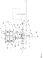
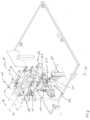
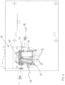
- the Figs. 1 to 3 show a transfer device 10, which in the case of the present embodiment is arranged in the product conveying direction between a first conveyor device 11 designed as a horizontal belt conveyor and a conveyor device 12 designed as a filling pipe of a filling device.
- a first conveyor device 11 designed as a horizontal belt conveyor
- a conveyor device 12 designed as a filling pipe of a filling device.
- products P are fed to a separating device arranged above the transfer device 10 and designed as a cascade container 13, which are conveyed along two essentially parallel conveyor lines 14, 15 on the conveyor device 11 to the transfer device 10.
- the products P in the present case are so-called "salami whips", i.e. segmented sausage products, which, as exemplified in Fig. 5 shown, have four salami segments S 1 , S 2 , S 3 and S 4 , each of which is essentially rigid and the sausage skin are connected to each other by hinge-like joints G.
- the containers 16 and the containers 17 are arranged at an increasing angle to one another in order to achieve an increasing horizontal distance between the products P before transfer to the transfer device 10.
- the cascade container 13 serves to enable a clocked transfer of the products P by the transfer device 10 after the products P in the upper containers 16 have been separated by the lower containers.
- the pivoting levers 21 of the pivoting conveyor 22 are arranged on a common first pivot axis 26, which is arranged parallel to the conveying plane F and parallel to the receiving plane E 1 and can be pivoted by means of a rotary drive 29 about a second pivot axis 27 arranged orthogonally to the conveying plane F or receiving plane E 1.
- the pivoting levers 21 are each driven independently of one another by a rotary drive 28 arranged on the pivot axis 26, such that the product receptacles 23 can be moved along a pivoting arc B independently of one another between the receiving plane E 1 and a Fig. 1 and 2 shown transfer level E 2 .
- the representation of the transfer device in Fig. 1 shows the arrangement of the first conveyor device 11, designed here as a belt conveyor, and the second conveyor device 12, designed here as a filling pipe of a filling device, with intersecting conveying directions, wherein in the present case a horizontal conveying direction towards the transfer device 10 is defined by means of the first conveyor device 11 and a conveying direction orthogonal to the first conveying direction 11 is defined by means of the second conveyor device 12.
- the first conveying direction 11 has two conveying lines 14, 15 formed next to one another in a common conveying plane F, along which the products P are each conveyed in a row arrangement, wherein the second conveyor device 12, designed as a filling pipe, defines only one conveying line 30, along which, after transfer of the products P from the product receptacles 23 into the filling pipe and which is arranged in the middle between the conveying lines 14, 15.
- a horizontal pivoting of the pivot axis 26 about the orthogonal pivot axis 27 is necessary in order to enable an overlapping arrangement of the containers 17 with the product receptacles 23 in the acceptance level E 1 and an overlapping arrangement of the product receptacles 23 with the conveying device 12 designed here as a filling pipe in the transfer level E 2 .
- the swivel conveyor 22 is shown in a configuration in which the left product holder 23 is arranged in the receiving level E 1 and the right product holder 23 is located in the transfer level E 2.
- the product holder 23 is provided with a drive pin 34 at a drive end 33 arranged on the joint axis 26, which is used for the force-locking connection with the Fig. 1 illustrated rotary drive 28.
- a lever end 35 opposite the drive end 33 is provided with the product receptacle 23, which is designed as a product tray with opposing tray walls 36, 37, which can be pivoted relative to one another via a pneumatically driven actuator 38, which is arranged on the pivoting lever 21, in such a way that a product receiving space 39 formed within the product receptacle 23 can be enlarged or reduced in its width b, wherein the tray walls 36, 37 are moved past a driver wall 40 forming the rear end of the product receptacle 23.
- Fig. 5 further shows, the product holder 23 is provided with a tray bottom 41, which is pivoted by means of a further actuator 42 also installed on the pivot lever 21 between a Fig. 5 shown lower position and one in Fig. 5 is adjustable in the upper position shown by the dash-dotted line, so that in addition to the width b, the height h of the product receiving space 3 can also be changed.
- Fig. 6 schematically shown using the example of the left product holder 32
- the swivel conveyor 22 is first swiveled 43 around the orthogonal swivel axis 27, so that the product holder 23 is in a Figs. 1 to 4 shown receiving position II, in which the product receptacle 23 is covered by the container 17, a door device 45 of the product receptacle 23 formed by the tray walls 36, 37 is in the open position, and the tray bottom 41 is arranged in its lower position.
- the product receptacle 23 is in the maximally expanded configuration, so that after the bottom flap 18 of the container 17 is opened, the product P can be received.
- the tray walls 36, 37 are pivoted against each other to close the door device 45, whereby at the same time or after reaching position III, the tray bottom 41 is adjusted to its upper position (see Fig.5 ), so that the tray bottom 41, which is adjustable by means of the actuator 42, forms a compression device 47 and the Fig. 5 the product P shown within the widened product receiving space 39 is compressed, with the result that the product segments S 1 to S 4 are converted into a more or less parallel and more closely spaced arrangement, thus significantly reducing the product volume.
- the product holder 23 is now pivoted along a pivoting arc B ( Fig. 2 ), during which the product P is accelerated and maintains the compressed configuration due to the centrifugal force acting on the product during the pivoting movement, so that the tray bottom 41 can be moved back into its lower position in order to enable the product receiving space 39 for a transfer of the product P into the second conveyor device 12 formed by the filling tube after stopping the pivoting movement after reaching the transfer position IV of the product holder 23 in the product transfer plane E 2 .
- the door device 45 Shortly before reaching the transfer position IV of the product holder 23, the door device 45 is opened by pivoting the tray walls 36, 37, so that the product P immediately before being transferred into the filling tube essentially only has physical contact with the product holder 23 via the carrier wall 40 and the kinetic energy imparted to the product P during the pivoting movement in the orthogonal pivoting plane ES in the product holder 23 is essentially available without restriction for ejecting the product into the filling tube.
- the right product holder While the left product holder 23 is in the transfer position IV, the right product holder is filled so that during the return movement of the left product holder 23 to the transfer level E 1, it executes a pivoting movement in the opposite direction to the pivoting movement of the left product holder 23 into the transfer position in the transfer level E 2 .
- the left and right product receptacles 23 are alternately pivoted between a receiving position II for receiving a product P from a conveyor line 14 or 15 and a transfer position IV for transferring the product P to the conveyor device 12 formed by the filling tube, such that one product receptacle 23 is in the receiving position II, while the other is arranged in the transfer position IV, a filling device arranged downstream of the second conveyor device 12 can be operated essentially continuously.
Landscapes
- Engineering & Computer Science (AREA)
- Mechanical Engineering (AREA)
- Life Sciences & Earth Sciences (AREA)
- Wood Science & Technology (AREA)
- Zoology (AREA)
- Food Science & Technology (AREA)
- Specific Conveyance Elements (AREA)
- Intermediate Stations On Conveyors (AREA)
Priority Applications (1)
| Application Number | Priority Date | Filing Date | Title |
|---|---|---|---|
| EP25163401.0A EP4545257A3 (fr) | 2022-12-16 | 2022-12-16 | Procédé et dispositif de transfert pour transférer des produits d'un premier convoyeur à un deuxième convoyeur |
Applications Claiming Priority (2)
| Application Number | Priority Date | Filing Date | Title |
|---|---|---|---|
| EP22214086.5A EP4385909B1 (fr) | 2022-12-16 | 2022-12-16 | Procédé et dispositif de transfert pour transférer des produits d'un premier convoyeur à un deuxième convoyeur |
| EP25163401.0A EP4545257A3 (fr) | 2022-12-16 | 2022-12-16 | Procédé et dispositif de transfert pour transférer des produits d'un premier convoyeur à un deuxième convoyeur |
Related Parent Applications (2)
| Application Number | Title | Priority Date | Filing Date |
|---|---|---|---|
| EP22214086.5A Division-Into EP4385909B1 (fr) | 2022-12-16 | 2022-12-16 | Procédé et dispositif de transfert pour transférer des produits d'un premier convoyeur à un deuxième convoyeur |
| EP22214086.5A Division EP4385909B1 (fr) | 2022-12-16 | 2022-12-16 | Procédé et dispositif de transfert pour transférer des produits d'un premier convoyeur à un deuxième convoyeur |
Publications (2)
| Publication Number | Publication Date |
|---|---|
| EP4545257A2 true EP4545257A2 (fr) | 2025-04-30 |
| EP4545257A3 EP4545257A3 (fr) | 2025-08-13 |
Family
ID=84537553
Family Applications (2)
| Application Number | Title | Priority Date | Filing Date |
|---|---|---|---|
| EP22214086.5A Active EP4385909B1 (fr) | 2022-12-16 | 2022-12-16 | Procédé et dispositif de transfert pour transférer des produits d'un premier convoyeur à un deuxième convoyeur |
| EP25163401.0A Pending EP4545257A3 (fr) | 2022-12-16 | 2022-12-16 | Procédé et dispositif de transfert pour transférer des produits d'un premier convoyeur à un deuxième convoyeur |
Family Applications Before (1)
| Application Number | Title | Priority Date | Filing Date |
|---|---|---|---|
| EP22214086.5A Active EP4385909B1 (fr) | 2022-12-16 | 2022-12-16 | Procédé et dispositif de transfert pour transférer des produits d'un premier convoyeur à un deuxième convoyeur |
Country Status (3)
| Country | Link |
|---|---|
| EP (2) | EP4385909B1 (fr) |
| ES (1) | ES3062914T3 (fr) |
| WO (1) | WO2024126015A1 (fr) |
Family Cites Families (8)
| Publication number | Priority date | Publication date | Assignee | Title |
|---|---|---|---|---|
| US4364467A (en) * | 1980-12-29 | 1982-12-21 | Baker Perkins Holdings Limited | Apparatus for handling biscuits |
| IT1138105B (it) * | 1981-07-24 | 1986-09-17 | Moss Srl | Dispositivo per trasferire oggetti sagomati da un primo ad un secondo nastro,disponendoli uniformemente orientati su quest'ultimo |
| JP4252852B2 (ja) * | 2002-09-02 | 2009-04-08 | 株式会社イシダ | 棒状物の方向転換装置 |
| US7438192B1 (en) * | 2004-05-28 | 2008-10-21 | Owens-Brockway Glass Container Inc. | Electronic control system for container indexing and inspection apparatus |
| ATE424350T1 (de) * | 2005-11-30 | 2009-03-15 | Sverre Stenbom | Verfahren und vorrichtung zum verpacken von lebensmitteln |
| IT1395041B1 (it) * | 2009-08-14 | 2012-09-05 | M C Automations S R L | Apparecchiatura per l'incarto di prodotti dolciari e simili |
| EP3178742B1 (fr) * | 2015-12-08 | 2019-04-17 | Marel A/S | Dispositif de préhension preneur-placeur destiné à capter et à repositionner un article alimentaire déformable et procédé de fabrication associé |
| EP3254994A1 (fr) * | 2016-06-10 | 2017-12-13 | Sidel Participations | Roue de transport servant à transporter des articles et appareil de manipulation d'articles comprenant au moins une telle roue |
-
2022
- 2022-12-16 EP EP22214086.5A patent/EP4385909B1/fr active Active
- 2022-12-16 EP EP25163401.0A patent/EP4545257A3/fr active Pending
- 2022-12-16 ES ES22214086T patent/ES3062914T3/es active Active
-
2023
- 2023-11-27 WO PCT/EP2023/083137 patent/WO2024126015A1/fr not_active Ceased
Also Published As
| Publication number | Publication date |
|---|---|
| EP4385909A1 (fr) | 2024-06-19 |
| ES3062914T3 (en) | 2026-04-14 |
| EP4385909B1 (fr) | 2025-12-03 |
| EP4545257A3 (fr) | 2025-08-13 |
| WO2024126015A1 (fr) | 2024-06-20 |
Similar Documents
| Publication | Publication Date | Title |
|---|---|---|
| CH669944A5 (fr) | ||
| DE2817094A1 (de) | Vorrichtung zum zusammenpressen und verpacken von gegenstaenden | |
| EP3181462B1 (fr) | Dispositif et procede de fixation de sacs d'aeration | |
| DE102007007068A1 (de) | Vorrichtung und Verfahren zum Befüllen von Behältern mit stabförmigen Produkten | |
| DE1917416A1 (de) | Verfahren und Vorrichtung zum UEberfuehren von Gegenstaenden | |
| DE3786746T2 (de) | Apparat zum transportieren und öffnen eines getränketrägers. | |
| DE60201425T3 (de) | Verfahren und vorrichtung zum schliessen einer schachtel durch falten einer lateralen schliessklappe | |
| EP1670706B1 (fr) | Dispositif de formation de piles | |
| EP2108271B9 (fr) | Cartouche de vidage et procédé de vidage de combles de puits remplis de produits en forme de tiges | |
| EP3269539B1 (fr) | Dispositif destiné à ouvrir une zone d'extrémité d'un corps de sachet tubulaire | |
| WO2016045965A2 (fr) | Procédé et dispositif pour la production d'unités de conditionnement | |
| DE102016014333A1 (de) | Verfahren und Vorrichtung zum Befüllen eines Behälters mit Produkten | |
| EP0332160A2 (fr) | Dispositif pour empiler des pièces de monnaie | |
| EP4545257A2 (fr) | Procédé et dispositif de transfert pour transférer des produits d'un premier convoyeur à un deuxième convoyeur | |
| DE2743899A1 (de) | Verfahren zum zufuehren von mit einem ventil versehenen saecken und vorrichtung fuer maschinen zum verpacken von pulverfoermigen stoffen | |
| DE68910438T2 (de) | Verfahren und Vorrichtung zum Aufrichten zusammengelegter rohrförmiger Zuschnitte. | |
| DE102012112699A1 (de) | Verfahren und Vorrichtung zur Herstellung einer Zigarettenpackung des Typs Shell and Slide | |
| DE1236921B (de) | Vorrichtung zum Entnehmen senkrecht gestapelter Faltschachtelzuschnitte aus einem Magazin | |
| DE102008009803B3 (de) | Vorrichtung zur Zuführung von einen Ausgießer aufweisenden Beuteln | |
| CH718811A2 (de) | Vorrichtung und Verfahren zur Eingabe von flachen Gegenständen in einen Transportbehälter. | |
| EP1712471B1 (fr) | Dispositif et procédé d'emballage d'articles | |
| DE69919477T2 (de) | Verfahren und Maschine zum Verpacken einer Gruppe von Gegenständen | |
| WO2002098738A1 (fr) | Dispositif pour prendre des sacs de supports de piles et pour les separer les uns des autres | |
| DE69211426T2 (de) | Verfahren und Vorrichtung zum Zuführen vorgeformter Schachteln zu einer Maschine, z. B. zu einer Maschine zum Füllen von Schachteln | |
| DE1028418B (de) | Falt- und Einsatzvorrichtung fuer Futterteile in Faltschachteln |
Legal Events
| Date | Code | Title | Description |
|---|---|---|---|
| PUAI | Public reference made under article 153(3) epc to a published international application that has entered the european phase |
Free format text: ORIGINAL CODE: 0009012 |
|
| STAA | Information on the status of an ep patent application or granted ep patent |
Free format text: STATUS: THE APPLICATION HAS BEEN PUBLISHED |
|
| AC | Divisional application: reference to earlier application |
Ref document number: 4385909 Country of ref document: EP Kind code of ref document: P |
|
| AK | Designated contracting states |
Kind code of ref document: A2 Designated state(s): AL AT BE BG CH CY CZ DE DK EE ES FI FR GB GR HR HU IE IS IT LI LT LU LV MC ME MK MT NL NO PL PT RO RS SE SI SK SM TR |
|
| REG | Reference to a national code |
Ref country code: DE Ref legal event code: R079 Free format text: PREVIOUS MAIN CLASS: B25J0015020000 Ipc: B65B0019340000 |
|
| PUAL | Search report despatched |
Free format text: ORIGINAL CODE: 0009013 |
|
| AK | Designated contracting states |
Kind code of ref document: A3 Designated state(s): AL AT BE BG CH CY CZ DE DK EE ES FI FR GB GR HR HU IE IS IT LI LT LU LV MC ME MK MT NL NO PL PT RO RS SE SI SK SM TR |
|
| RIC1 | Information provided on ipc code assigned before grant |
Ipc: B65B 19/34 20060101AFI20250704BHEP Ipc: A22C 11/00 20060101ALI20250704BHEP Ipc: B65G 47/252 20060101ALI20250704BHEP Ipc: B65B 35/32 20060101ALI20250704BHEP Ipc: B65B 35/36 20060101ALI20250704BHEP Ipc: B65B 35/56 20060101ALI20250704BHEP Ipc: B65B 63/02 20060101ALI20250704BHEP Ipc: B65G 47/68 20060101ALN20250704BHEP Ipc: B65G 47/90 20060101ALN20250704BHEP |
|
| STAA | Information on the status of an ep patent application or granted ep patent |
Free format text: STATUS: REQUEST FOR EXAMINATION WAS MADE |
|
| 17P | Request for examination filed |
Effective date: 20260209 |