EP4545271A1 - Installation de fabrication de récipients à partir de préformes - Google Patents
Installation de fabrication de récipients à partir de préformes Download PDFInfo
- Publication number
- EP4545271A1 EP4545271A1 EP24189451.8A EP24189451A EP4545271A1 EP 4545271 A1 EP4545271 A1 EP 4545271A1 EP 24189451 A EP24189451 A EP 24189451A EP 4545271 A1 EP4545271 A1 EP 4545271A1
- Authority
- EP
- European Patent Office
- Prior art keywords
- preforms
- transport device
- temperature
- storage device
- transport
- Prior art date
- Legal status (The legal status is an assumption and is not a legal conclusion. Google has not performed a legal analysis and makes no representation as to the accuracy of the status listed.)
- Pending
Links
Images

Classifications
-
- B—PERFORMING OPERATIONS; TRANSPORTING
- B29—WORKING OF PLASTICS; WORKING OF SUBSTANCES IN A PLASTIC STATE IN GENERAL
- B29C—SHAPING OR JOINING OF PLASTICS; SHAPING OF MATERIAL IN A PLASTIC STATE, NOT OTHERWISE PROVIDED FOR; AFTER-TREATMENT OF THE SHAPED PRODUCTS, e.g. REPAIRING
- B29C49/00—Blow-moulding, i.e. blowing a preform or parison to a desired shape within a mould; Apparatus therefor
- B29C49/42—Component parts, details or accessories; Auxiliary operations
- B29C49/64—Heating or cooling preforms, parisons or blown articles
- B29C49/6409—Thermal conditioning of preforms
- B29C49/6418—Heating of preforms
-
- B—PERFORMING OPERATIONS; TRANSPORTING
- B29—WORKING OF PLASTICS; WORKING OF SUBSTANCES IN A PLASTIC STATE IN GENERAL
- B29C—SHAPING OR JOINING OF PLASTICS; SHAPING OF MATERIAL IN A PLASTIC STATE, NOT OTHERWISE PROVIDED FOR; AFTER-TREATMENT OF THE SHAPED PRODUCTS, e.g. REPAIRING
- B29C49/00—Blow-moulding, i.e. blowing a preform or parison to a desired shape within a mould; Apparatus therefor
- B29C49/42—Component parts, details or accessories; Auxiliary operations
- B29C49/4205—Handling means, e.g. transfer, loading or discharging means
- B29C49/42093—Transporting apparatus, e.g. slides, wheels or conveyors
- B29C49/42107—Transporting apparatus, e.g. slides, wheels or conveyors with accumulator or temporary storage, e.g. while waiting for the blowing apparatus
- B29C49/42109—Transporting apparatus, e.g. slides, wheels or conveyors with accumulator or temporary storage, e.g. while waiting for the blowing apparatus keeping temperature of accumulated preforms or articles, e.g. the accumulator being an oven
-
- B—PERFORMING OPERATIONS; TRANSPORTING
- B29—WORKING OF PLASTICS; WORKING OF SUBSTANCES IN A PLASTIC STATE IN GENERAL
- B29C—SHAPING OR JOINING OF PLASTICS; SHAPING OF MATERIAL IN A PLASTIC STATE, NOT OTHERWISE PROVIDED FOR; AFTER-TREATMENT OF THE SHAPED PRODUCTS, e.g. REPAIRING
- B29C49/00—Blow-moulding, i.e. blowing a preform or parison to a desired shape within a mould; Apparatus therefor
- B29C49/02—Combined blow-moulding and manufacture of the preform or the parison
- B29C49/06—Injection blow-moulding
-
- B—PERFORMING OPERATIONS; TRANSPORTING
- B29—WORKING OF PLASTICS; WORKING OF SUBSTANCES IN A PLASTIC STATE IN GENERAL
- B29C—SHAPING OR JOINING OF PLASTICS; SHAPING OF MATERIAL IN A PLASTIC STATE, NOT OTHERWISE PROVIDED FOR; AFTER-TREATMENT OF THE SHAPED PRODUCTS, e.g. REPAIRING
- B29C49/00—Blow-moulding, i.e. blowing a preform or parison to a desired shape within a mould; Apparatus therefor
- B29C49/42—Component parts, details or accessories; Auxiliary operations
- B29C49/4205—Handling means, e.g. transfer, loading or discharging means
- B29C49/42065—Means specially adapted for transporting preforms
-
- B—PERFORMING OPERATIONS; TRANSPORTING
- B29—WORKING OF PLASTICS; WORKING OF SUBSTANCES IN A PLASTIC STATE IN GENERAL
- B29C—SHAPING OR JOINING OF PLASTICS; SHAPING OF MATERIAL IN A PLASTIC STATE, NOT OTHERWISE PROVIDED FOR; AFTER-TREATMENT OF THE SHAPED PRODUCTS, e.g. REPAIRING
- B29C49/00—Blow-moulding, i.e. blowing a preform or parison to a desired shape within a mould; Apparatus therefor
- B29C49/42—Component parts, details or accessories; Auxiliary operations
- B29C49/4205—Handling means, e.g. transfer, loading or discharging means
- B29C49/42071—Temperature conditioned transport, e.g. insulated or heated transport means
-
- B—PERFORMING OPERATIONS; TRANSPORTING
- B29—WORKING OF PLASTICS; WORKING OF SUBSTANCES IN A PLASTIC STATE IN GENERAL
- B29C—SHAPING OR JOINING OF PLASTICS; SHAPING OF MATERIAL IN A PLASTIC STATE, NOT OTHERWISE PROVIDED FOR; AFTER-TREATMENT OF THE SHAPED PRODUCTS, e.g. REPAIRING
- B29C49/00—Blow-moulding, i.e. blowing a preform or parison to a desired shape within a mould; Apparatus therefor
- B29C49/42—Component parts, details or accessories; Auxiliary operations
- B29C49/64—Heating or cooling preforms, parisons or blown articles
- B29C49/6409—Thermal conditioning of preforms
-
- B—PERFORMING OPERATIONS; TRANSPORTING
- B29—WORKING OF PLASTICS; WORKING OF SUBSTANCES IN A PLASTIC STATE IN GENERAL
- B29C—SHAPING OR JOINING OF PLASTICS; SHAPING OF MATERIAL IN A PLASTIC STATE, NOT OTHERWISE PROVIDED FOR; AFTER-TREATMENT OF THE SHAPED PRODUCTS, e.g. REPAIRING
- B29C49/00—Blow-moulding, i.e. blowing a preform or parison to a desired shape within a mould; Apparatus therefor
- B29C49/42—Component parts, details or accessories; Auxiliary operations
- B29C49/78—Measuring, controlling or regulating
- B29C49/786—Temperature
-
- B—PERFORMING OPERATIONS; TRANSPORTING
- B29—WORKING OF PLASTICS; WORKING OF SUBSTANCES IN A PLASTIC STATE IN GENERAL
- B29C—SHAPING OR JOINING OF PLASTICS; SHAPING OF MATERIAL IN A PLASTIC STATE, NOT OTHERWISE PROVIDED FOR; AFTER-TREATMENT OF THE SHAPED PRODUCTS, e.g. REPAIRING
- B29C49/00—Blow-moulding, i.e. blowing a preform or parison to a desired shape within a mould; Apparatus therefor
- B29C49/02—Combined blow-moulding and manufacture of the preform or the parison
- B29C2049/023—Combined blow-moulding and manufacture of the preform or the parison using inherent heat of the preform, i.e. 1 step blow moulding
-
- B—PERFORMING OPERATIONS; TRANSPORTING
- B29—WORKING OF PLASTICS; WORKING OF SUBSTANCES IN A PLASTIC STATE IN GENERAL
- B29C—SHAPING OR JOINING OF PLASTICS; SHAPING OF MATERIAL IN A PLASTIC STATE, NOT OTHERWISE PROVIDED FOR; AFTER-TREATMENT OF THE SHAPED PRODUCTS, e.g. REPAIRING
- B29C49/00—Blow-moulding, i.e. blowing a preform or parison to a desired shape within a mould; Apparatus therefor
- B29C49/02—Combined blow-moulding and manufacture of the preform or the parison
- B29C2049/024—Combined blow-moulding and manufacture of the preform or the parison not using inherent heat of the preform, i.e. 2 step blow moulding
-
- B—PERFORMING OPERATIONS; TRANSPORTING
- B29—WORKING OF PLASTICS; WORKING OF SUBSTANCES IN A PLASTIC STATE IN GENERAL
- B29C—SHAPING OR JOINING OF PLASTICS; SHAPING OF MATERIAL IN A PLASTIC STATE, NOT OTHERWISE PROVIDED FOR; AFTER-TREATMENT OF THE SHAPED PRODUCTS, e.g. REPAIRING
- B29C49/00—Blow-moulding, i.e. blowing a preform or parison to a desired shape within a mould; Apparatus therefor
- B29C49/42—Component parts, details or accessories; Auxiliary operations
- B29C49/78—Measuring, controlling or regulating
- B29C49/786—Temperature
- B29C2049/7861—Temperature of the preform
-
- B—PERFORMING OPERATIONS; TRANSPORTING
- B29—WORKING OF PLASTICS; WORKING OF SUBSTANCES IN A PLASTIC STATE IN GENERAL
- B29C—SHAPING OR JOINING OF PLASTICS; SHAPING OF MATERIAL IN A PLASTIC STATE, NOT OTHERWISE PROVIDED FOR; AFTER-TREATMENT OF THE SHAPED PRODUCTS, e.g. REPAIRING
- B29C49/00—Blow-moulding, i.e. blowing a preform or parison to a desired shape within a mould; Apparatus therefor
- B29C49/42—Component parts, details or accessories; Auxiliary operations
- B29C49/78—Measuring, controlling or regulating
- B29C49/786—Temperature
- B29C2049/7861—Temperature of the preform
- B29C2049/7862—Temperature of the preform characterised by temperature values or ranges
-
- B—PERFORMING OPERATIONS; TRANSPORTING
- B29—WORKING OF PLASTICS; WORKING OF SUBSTANCES IN A PLASTIC STATE IN GENERAL
- B29C—SHAPING OR JOINING OF PLASTICS; SHAPING OF MATERIAL IN A PLASTIC STATE, NOT OTHERWISE PROVIDED FOR; AFTER-TREATMENT OF THE SHAPED PRODUCTS, e.g. REPAIRING
- B29C49/00—Blow-moulding, i.e. blowing a preform or parison to a desired shape within a mould; Apparatus therefor
- B29C49/42—Component parts, details or accessories; Auxiliary operations
- B29C49/78—Measuring, controlling or regulating
- B29C49/786—Temperature
- B29C2049/7867—Temperature of the heating or cooling means
- B29C2049/78675—Temperature of the heating or cooling means of the heating means
-
- B—PERFORMING OPERATIONS; TRANSPORTING
- B29—WORKING OF PLASTICS; WORKING OF SUBSTANCES IN A PLASTIC STATE IN GENERAL
- B29C—SHAPING OR JOINING OF PLASTICS; SHAPING OF MATERIAL IN A PLASTIC STATE, NOT OTHERWISE PROVIDED FOR; AFTER-TREATMENT OF THE SHAPED PRODUCTS, e.g. REPAIRING
- B29C49/00—Blow-moulding, i.e. blowing a preform or parison to a desired shape within a mould; Apparatus therefor
- B29C49/42—Component parts, details or accessories; Auxiliary operations
- B29C49/78—Measuring, controlling or regulating
- B29C2049/7878—Preform or article handling, e.g. flow from station to station
-
- B—PERFORMING OPERATIONS; TRANSPORTING
- B29—WORKING OF PLASTICS; WORKING OF SUBSTANCES IN A PLASTIC STATE IN GENERAL
- B29C—SHAPING OR JOINING OF PLASTICS; SHAPING OF MATERIAL IN A PLASTIC STATE, NOT OTHERWISE PROVIDED FOR; AFTER-TREATMENT OF THE SHAPED PRODUCTS, e.g. REPAIRING
- B29C2949/00—Indexing scheme relating to blow-moulding
- B29C2949/07—Preforms or parisons characterised by their configuration
- B29C2949/0715—Preforms or parisons characterised by their configuration the preform having one end closed
-
- B—PERFORMING OPERATIONS; TRANSPORTING
- B29—WORKING OF PLASTICS; WORKING OF SUBSTANCES IN A PLASTIC STATE IN GENERAL
- B29C—SHAPING OR JOINING OF PLASTICS; SHAPING OF MATERIAL IN A PLASTIC STATE, NOT OTHERWISE PROVIDED FOR; AFTER-TREATMENT OF THE SHAPED PRODUCTS, e.g. REPAIRING
- B29C49/00—Blow-moulding, i.e. blowing a preform or parison to a desired shape within a mould; Apparatus therefor
- B29C49/42—Component parts, details or accessories; Auxiliary operations
- B29C49/4205—Handling means, e.g. transfer, loading or discharging means
- B29C49/42051—Means for stripping, aligning or de-stacking
- B29C49/42057—Aligning disorderly arranged preforms, e.g. delivered disorderly
-
- B—PERFORMING OPERATIONS; TRANSPORTING
- B29—WORKING OF PLASTICS; WORKING OF SUBSTANCES IN A PLASTIC STATE IN GENERAL
- B29C—SHAPING OR JOINING OF PLASTICS; SHAPING OF MATERIAL IN A PLASTIC STATE, NOT OTHERWISE PROVIDED FOR; AFTER-TREATMENT OF THE SHAPED PRODUCTS, e.g. REPAIRING
- B29C49/00—Blow-moulding, i.e. blowing a preform or parison to a desired shape within a mould; Apparatus therefor
- B29C49/42—Component parts, details or accessories; Auxiliary operations
- B29C49/4205—Handling means, e.g. transfer, loading or discharging means
- B29C49/42093—Transporting apparatus, e.g. slides, wheels or conveyors
-
- B—PERFORMING OPERATIONS; TRANSPORTING
- B29—WORKING OF PLASTICS; WORKING OF SUBSTANCES IN A PLASTIC STATE IN GENERAL
- B29C—SHAPING OR JOINING OF PLASTICS; SHAPING OF MATERIAL IN A PLASTIC STATE, NOT OTHERWISE PROVIDED FOR; AFTER-TREATMENT OF THE SHAPED PRODUCTS, e.g. REPAIRING
- B29C49/00—Blow-moulding, i.e. blowing a preform or parison to a desired shape within a mould; Apparatus therefor
- B29C49/42—Component parts, details or accessories; Auxiliary operations
- B29C49/42378—Handling malfunction
-
- B—PERFORMING OPERATIONS; TRANSPORTING
- B29—WORKING OF PLASTICS; WORKING OF SUBSTANCES IN A PLASTIC STATE IN GENERAL
- B29L—INDEXING SCHEME ASSOCIATED WITH SUBCLASS B29C, RELATING TO PARTICULAR ARTICLES
- B29L2031/00—Other particular articles
- B29L2031/712—Containers; Packaging elements or accessories, Packages
Definitions
- the present invention relates to a plant for producing containers from preforms according to claim 1 and to a method for producing containers with a plant according to claim 9.
- Plants for producing containers from preforms are generally known. These can be implemented as single-stage or two-stage processes.
- preforms are produced in an injection molding machine and fed to a machine for producing containers from preforms (especially blow molding machines) via a conveyor system that is usually very short, allows the preforms to be handled in a defined manner, and receives a large portion of the heat from the injection molding.
- the preforms are produced separately and fed, for example, via truck transport routes to the plants that produce containers from the preforms.
- a direct connection between preform production and container production is possible; however, the preform must be reheated rather than just conditioned.
- the reliable manufacture of containers depends on the production machine for producing the preforms (for example, an injection molding machine) and the blow molding machine being synchronized so that they have essentially the same throughput. Otherwise, the preforms from the blow molding machine can back up or the blow molding machine can run idle. Both have a negative impact on operation and, in particular, backing up of the preforms can lead to them not being sufficiently tempered to be reliably formed into containers.
- both the one-stage and two-stage processes require heating or tempering of the preforms to a specific target temperature. However, due to possible variability in the preform feed, this can sometimes be difficult to achieve with sufficient accuracy.
- the technical problem to be solved is to provide a plant for producing containers from preforms and a method for the production of containers from preforms, which enable reliable operation of the plant and, at the same time, high quality of the containers produced to be achieved.
- the system according to the invention for producing containers from preforms comprises a production machine for producing preforms, a blow molding machine for producing containers from preforms, a transport device for feeding preforms from the production machine to the blow molding machine and a storage device to which preforms can be fed from the transport device at a removal point and transferred to the transport device at a transfer point, wherein the storage device comprises a tempering device for tempering the preforms.
- the transport device can, in principle, be designed in any desired manner.
- the transport device can comprise a linear conveyor (e.g., an air conveyor) and/or a number of rotating star wheels that transport the preforms from the production machine to the blow molding machine.
- the transport device can also comprise a sorting device that at least partially changes the spatial arrangement of the preforms after they leave the production machine and enables transfer to the blow molding machine.
- a switch or a controlled rotating star wheel can be provided at the removal point and/or the transfer point, which, as required, either feeds the preforms to the storage device or moves them further in the transport device in order to feed them to the blow moulding machine for producing containers from the preforms.
- the storage device can enable the preforms to be stored or accumulated in an orderly or disorderly manner.
- Orderly storage or accumulation of the preforms can in particular comprise storing the preforms in a specific spatial orientation (for example, hanging vertically), whereas disordered storage of the preforms can comprise storing the preforms without a predetermined spatial orientation.
- Orientation can be realized, for example, in the form of a silo, a box, or other receptacle for preforms.
- the tempered preforms can in principle be removed from the storage device at any time and fed to the transport device, optionally even when the production machine is still in operation, i.e. in particular when producing preforms. This can take place, for example, depending on the storage capacity of the storage device, intermittently with the usual feeding of the preforms from the production machine to the blow molding machine. If the storage device is full or reaches a certain fill level (for example 60%, 70%, or 80%), the storage device can be at least partially emptied by feeding at least a portion of the preforms from the storage device to the transport device (for example enough preforms to reduce the fill level of the storage device to a predetermined value of at most 50%, or at most 30%, or any other value), so that it does not become overfilled. Alternatively or additionally, at least some of the preforms can be fed from the storage device to the transport device depending on the temperature of the preforms.
- a certain fill level for example 60%, 70%, or 80%
- the storage device can be at least partially emptied
- the preforms are partially or completely removed from the storage device and fed to the transport device. This can occur, for example, during predetermined operating breaks in the process cycle of the production machine, but is not limited to this.
- the temperature control device can, for example, comprise one or more infrared radiators and/or microwave radiators and/or a hot air supply in order to temperature control the preforms, in particular to maintain them at a desired temperature.
- the temperature control device can also, for example, comprise a plurality of heating elements, such as infrared radiators and/or microwave radiators and/or hot air supplies (or any other suitable heat source), which are arranged in different areas of the storage device, wherein preforms pass through the heating elements successively or in a cascade-like manner during transport through the storage device and/or the temperature control device.
- Each of the heating elements can be designed such that it can temperature control preforms to a specific temperature, wherein, for example, heating elements arranged one after the other in the transport direction can be arranged from lower to higher temperature in the transport direction of the preforms through the storage device.
- the preforms in the storage device are permanently tempered.
- the tempering device does not have to be continuously active when preforms are present in the storage device.
- the tempering of the preforms is linked to or dependent on certain process parameters. These include, for example, predetermined downtimes of the production machine (such as scheduled maintenance intervals or a scheduled end of operation). Alternatively or additionally, it can also be provided that the tempering of the preforms is controlled, for example, depending on energy costs.
- the tempering device can be switched on at times when the external power grid supplies a surplus of power or a surplus of available electricity that exceeds the demand of other consumers, or at times when such a surplus is likely. Available renewable energy is thus used efficiently. At the same time, this can bring advantages in terms of operating costs.
- the manufacturing machine can, in principle, be any machine suitable for producing preforms from a preform starting material (e.g., PET pellets) by, for example, melting the preform starting material and introducing the molten preform starting material into a mold or tool.
- a preform starting material e.g., PET pellets
- the manufacturing machine can, in particular, be configured as an injection molding machine, although other variants known from the prior art, such as a compression molding machine, can also be used.
- the invention is not limited in this regard.
- the system according to the invention ensures that the preforms produced by the injection molding machine do not have to be rejected as scrap, even if the blow molding machine is stopped, but can be fed back into the conveyor system for further use. This improves the operation of the system and the quality of the produced containers, while simultaneously minimizing waste.
- the removal point is located upstream or downstream of the transfer point in the transport direction of the preforms in the transport device.
- the feeding of the preforms to a transfer point upstream or downstream of the removal point can be selected, for example, depending on the presence of a sorting device and/or the random or ordered storage of the preforms in the storage device. to ensure the reliable feeding of the preforms to the transport device.
- the system comprises a control unit for controlling the tempering device depending on a target temperature of the preforms.
- the target temperature can, in particular, be a temperature that the preforms must have upon transfer to the transport device or depend on this temperature.
- a target temperature of the preforms upon input into the blow molding machine can be selected as the target temperature, or the target temperature can depend on how high the temperature of the preforms must be upon input to the blow molding machine.
- the target temperature can then be determined, for example, taking into account the transport distance and the expected cooling of the preforms during transport.
- the temperature control device can then be controlled with regard to the power or heat it outputs so that the target temperature of the preforms is reached in the storage device.
- preforms that have reached the target temperature are fed from the storage device to the transport device. This can occur either at specified time intervals (for example, every 30 minutes, all preforms in the storage device that have reached the target temperature can be fed from the storage device to the transport device) or depending on whether one or more preforms have reached the target temperature.
- This embodiment can advantageously be implemented together with an orderly storage of the preforms in the storage device, but is not limited to this.
- the system comprises a sensor for determining a temperature of preforms in the transport device, and wherein the target temperature is dependent on the determined temperature and/or on requirements when producing containers from the preforms with the blow molding machine.
- the requirements when producing the containers from the preforms with the blow molding machine can, for example, be a necessary temperature of the preforms when feeding the preforms to the blow molding machine. and/or a heating device (oven) of the blow molding machine.
- These requirements can, for example, be used in addition to or alternatively to the specific temperature to determine the target temperature of the preforms. For example, extrapolating the cooling of the preforms from the transfer point to the point at which the preforms are transferred to the blow molding machine can be used to determine the target temperature based on the temperature to be achieved when the preforms are transferred to the blow molding machine.
- the sensor can, in particular, be a thermal sensor that can determine the temperature of preforms (for example, based on infrared radiation emitted by the preforms and/or a radiation spectrum of the preforms).
- the temperature of the preforms in the transport device can be determined at any point along the transport device, and the target temperature can be dependent on this specific temperature. This ensures that the temperature of the preforms returned to the transport device corresponds to the temperature of the preforms transported in the transport device, so that the result when manufacturing the containers is as consistent as possible.
- the sensor can be arranged so that it can determine the temperature of the preforms in a region of the transfer point.
- the target temperature of the preforms can preferably be selected so that it corresponds to the temperature of the preforms in the transport device at the transfer point, so that all preforms have the same temperature at the transfer point, regardless of whether they are fed from the storage device to the transport device or are transported in the transport device.
- the containers can thus be manufactured from the preforms with consistent quality.
- the area of the transfer point is understood here as an area in the transport device that can extend around the transfer point.
- the sensor can preferably be arranged such that it can determine the temperature of the preforms directly at the transfer point or in an area that extends, for example, up to 10, 20, or 50 cm upstream or downstream of the transport device.
- sensors can also be provided, arranged one after the other in the transport direction of the preforms, in order to determine not only the temperature of the preforms at a specific point, but also a temperature profile of the preforms during transport. This temperature profile can also be used instead of the determined temperature to determine the target temperature, which may be possible with greater accuracy.
- the control unit can be designed to control the tempering device such that the preforms have the target temperature at a transfer time.
- the temperature control device can be switched on and/or off and/or its power can be controlled such that the preforms have the target temperature upon reaching the transfer time.
- the temperature control device can either be controlled such that the preforms have the desired target temperature on average (on average over the temperature of a large number of preforms that are simultaneously in the storage device but were fed to it at different times), or the temperature control device can be designed such that it can temperature-control preforms fed in at different times differently, for example by providing several independently controllable heaters that can heat specific areas of the storage device to which the preforms are fed depending on the time they are fed to the storage device. This allows energy to be saved because the temperature control device can be controlled so that only the heat energy required to reach the target temperature is released.
- control unit is designed to control the tempering device depending on a planned end of operation of the production machine such that the preforms have the target temperature at the planned end of operation.
- the planned end of operation can, for example, be a time when a container type is changed, a maintenance interval, or another interruption in the operation of the production machine.
- the end of operation of the production machine is not synonymous with the end of operation of the system, but simply means that the production machine is no longer producing any more preforms.
- preforms since preforms may still be present in the storage device, they can be further processed by the blow molding machine after the production machine has shut down. This simplifies the feeding of the preforms from the storage device to the transport device during operation and simultaneously minimizes waste, since the preforms are preferably completely formed into containers.
- the system can be designed in such a way that the preforms are fed to the transport device from the storage device when there are no more preforms in the transport device upstream of the transfer point.
- the preforms from the production machine continue to be fed to the blow molding machine without any new preforms being added. This means that for a certain time after the production machine has shut down, there are no more preforms upstream of the transfer point, allowing the preforms from the storage device to be fed unhindered to the transport device.
- a method for producing containers from preforms is further provided with a system, the system comprising a production machine for producing preforms, a blow molding machine for producing containers from preforms, a transport device for feeding preforms from the production machine to the blow molding machine and a storage device to which preforms can be fed from the transport device at a removal point and transferred to the transport device at a transfer point, wherein the storage device comprises a tempering device for tempering the preforms, the method comprising feeding preforms from the storage device to the transport device when there are at least temporarily no preforms upstream of the transfer point.
- This process enables reliable production of containers from preforms while simultaneously reducing waste.
- the removal point can be arranged upstream or downstream of the transfer point in the transport direction of the preforms in the transport system.
- the arrangement of the removal point and transfer point can be selected according to practical requirements to ensure reliable operation of the system.
- the system may include a control unit that controls the temperature control device depending on a target preform temperature. This ensures reliable production of containers from preforms from the storage device.
- the system comprises a sensor for determining a temperature of preforms in the transport device and wherein the target temperature depends of the determined temperature, wherein optionally the sensor is arranged to determine the temperature of the preforms in a region of the transfer point.
- This embodiment ensures the consistent quality of the containers produced from preforms, regardless of whether they are fed directly from the production machine to the blow molding machine or whether they are temporarily stored in the storage device.
- control unit controls the tempering device so that the preforms have the target temperature at a transfer time. This allows the energy required for tempering the preforms to be reduced.
- the control unit can be configured to control the temperature control device depending on the planned end of operation of the production machine so that the preforms are at the target temperature at the planned end of operation. This allows for a smooth feeding of the preforms stored in the storage device to the transport device.
- the control unit can determine the end of operation based on the number of preforms in the storage device and/or based on the number of containers to be produced. This embodiment can ensure that sufficient containers are produced while simultaneously minimizing waste.
- Fig. 1 shows a system for producing containers 132 from preforms 130.
- the system comprises a manufacturing machine 101 with which preforms 130 can be produced.
- the manufacturing machine 101 can, for example, be designed as an injection molding machine in which heated preform starting material (for example PET) is fed to a tool in which the preforms are formed by injecting the heated preform starting material. The preforms can then optionally cool and be removed from the tool.
- heated preform starting material for example PET
- an injection molding machine or a compression molding machine can also be used as the production machine. All of these machines are basically known from the prior art and will not be described further here with regard to their further design.
- the invention is fundamentally not limited with regard to the design of the production machine.
- the system 100 further comprises a blow molding machine 102 for producing containers 132 from the preforms 130.
- the blow molding machine 102 can, for example, be designed as a stretch blow molding machine and, through the action of compressed air and/or a stretching rod in the interior of the preform, cause the preform to expand so that its outer surface contacts the inner wall of a blow mold of the blow molding machine.
- Corresponding blow molding machines are well known in the art, and the blow molding machine 102 can, in particular, be designed as a rotary machine with a carousel that is rotatably mounted about a rotational axis and on whose periphery a number of blow molds are arranged for receiving and forming preforms into containers.
- the invention is not limited in this regard, and any blow molding machine with which containers can be produced from preforms can be provided.
- a transport device 103 is provided, with which the preforms are fed from the production machine 101 to the blow molding machine 102.
- the transport device 103 can, in principle, be designed as desired.
- the transport device 103 can comprise an air conveyor, with which the preforms are transported, for example, suspended from their support ring between air conveyor rails and by generating a compressed air flow in the direction of the blow molding machine.
- a conveyor inclined downwards in the transport direction in which the direction of gravity can be provided, in which the preforms can be transported solely or essentially due to the force of gravity acting on them.
- one or more rotary star wheels can also be provided, which can pick up the preforms, for example, by means of individually actuated clamps on the circumference of the rotary star wheels, and can transport them from the production machine 101 towards the blow molding machine.
- Transport devices that transport preforms using electromagnetic forces are also conceivable. In particular, long stators with movers arranged on them, which can move one or more preforms can be provided. Combinations of these or other transport devices can also be provided, which enable the preforms to be transferred from the production machine to the blow molding machine 102.
- a sorting device 131 shown only schematically here, can be arranged either in the area of the transport device or as part of the production machine 101.
- This sorting device sorts the preforms coming out of the production machine 101.
- the sorting of preforms refers to any manipulation of the arrangement of the preforms that imposes a new orientation or arrangement on the preforms from an initial orientation or arrangement (which may be ordered or disordered, in particular random or chaotic).
- the sorting device 131 can be designed such that, after receiving the disordered preforms, it aligns the preforms such that they are transferred to the transport device 103, for example, all hanging from their support ring and aligned so that the opening area of the preform faces upwards.
- the transport device 103 can be designed, for example, in two parts, with a first part of the transport device extending from the production machine 101 to the sorting device 131.
- This part of the transport device can, for example, enable random transport of preforms coming from the production machine and can be designed, for example, as a conveyor belt. These preforms can then be sorted in the sorting device 131 and subsequently fed with the intended orientation to a second part of the transport device 103, which can then be designed, for example, as an air conveyor and/or comprising one or more rotary star wheels.
- the sorting device is designed to enable transfer to the second part of the transport device.
- Such sorting devices are generally known from the prior art and include, for example, roller sorters or disc sorters.
- the blow molding machine 102 can optionally also include a heating device arranged upstream of a blow molding area in which the preforms are formed into containers.
- the heating device can include one or more heaters, for example, infrared heaters or microwave heaters, which temper the preforms to a specific temperature. after they have been transferred to this heating device from the transport device 103.
- the imprinting of a desired temperature profile (a temperature curve, for example, along the length of the preform) into the preform can also be provided.
- the system 100 further comprises a storage device 104 to which preforms can be fed.
- a storage device 104 to which preforms can be fed.
- This is achieved by removing the preforms from the transport device 103 at a removal point 141 and feeding them, for example, via a suitable transport device 143, to the storage device 104.
- the transport device 143 (also discharge transport device) is connected to the transport device 103 in such a way that preforms can preferably be selectively removed from the transport device 103 at the removal point 141 and fed to the transport device 143.
- This can be achieved, for example, by arranging a switch in an air conveyor for conveying the preforms as the transport device 103, so that the air conveyor can branch off in the direction of the storage device 104 at the removal point 141. If the switch is switched and/or a blocking element is actuated to block the transport device 103 downstream of the switch, the preforms can be diverted into the transport device 143.
- the transport device 103 is designed as a series of rotating stars, it can be provided that a rotating star in the removal point 141 can be controlled in order to either transfer the preforms to a subsequent rotating star in the transport direction towards the blow molding machine 102 or to transfer the preforms to a rotating star of the transport device 143 so that they can be fed to the storage device 104.
- preforms from the storage device 104 can be fed again to the transport device 103 at a transfer point 142.
- a further transport device 144 also feed transport device
- This can be implemented analogously to the design of the transport device 143 at the removal point 141.
- the further transport device 144 is also designed for the random transport of the preforms from the storage device 104, for example as a chute on which the preforms can be conveyed along a gradient from the storage device 104 towards the transfer point 142.
- the storage device 104 can be designed for the orderly or disordered storage or warehousing of preforms. If the storage device 104 is designed for the orderly storage of the preforms, the storage device can be designed, for example, as a storage rail or as a buffer system in which the preforms are kept in a specific orientation. If the storage device 104 is designed for the storage of preforms in the form of a disordered supply, it can be provided that the storage device comprises, for example, a receiving container, such as a silo or the like, to which the preforms are fed and in which they are stored in a disordered manner or without any imposed order. In this embodiment, it is particularly advantageous if the further transport device 144 is designed for the disordered transport of the preforms.
- the storage device comprises a tempering device 105 for tempering the preforms in the storage device 104.
- the tempering device 105 can, for example, comprise one or more microwave radiators or infrared radiators or also comprise a warm air blower with which the preforms can be subjected to thermal energy.
- the temperature control device 105 comprises a plurality of heating elements, such as the described microwave radiators and/or infrared radiators, along a transport direction of the preforms in the storage device 104. Their temperature and/or emitted heat output can then be controlled such that heating elements arranged downstream in the transport direction of the preforms in the storage device each have a higher temperature than the heating element arranged immediately upstream.
- Each heating element can comprise an individual microwave radiator and/or infrared radiator (or similar heat source), or each heating element can also comprise a plurality of heat sources (microwave radiators and/or infrared radiators or similar) set to the same temperature and/or heat output in the sense of a group.
- the removal point 141 is located downstream of the transfer point 142. However, this is not mandatory.
- the removal point 141 can also be arranged upstream of the transfer point 142, viewed in the transport direction of the preforms in the transport direction 103.
- the distance between the transfer point and the removal point is not limited according to the invention, but preferably extends such that, if a sorting device 131 is provided, the removal point after the sorting device (downstream) in the transport device 103, and the transfer point upstream of the sorting device 131 in the transport direction of the preforms in the transport device 103. This allows the preforms fed from the transport device 103 to the storage device to be stored in the storage device in an unsorted manner. This can facilitate the storage of the preforms.
- a control unit 180 for example in the form of a computer with associated memory and processor, can be provided as part of the system, which can be designed to control the temperature control device 105 and/or the removal of preforms from the transport device 103 to the storage device 104 and/or the feeding of preforms to the transport device from the storage device.
- This can, for example, comprise the control unit controlling the temperature control device depending on certain further parameters, for example a (target) temperature to be achieved by the preforms when they are transferred to the transport device from the storage device, or the tempering of the preforms to a temperature which they are to assume at the end of operation of the production machine. This will be explained in more detail with regard to the Fig. 2 and 3 further described.
- one or more sensors 161 to 163 can be arranged in the region of the transport device 103 to determine the temperature of the preforms in the transport device.
- a further sensor 164 can also be provided in the region of the storage device to determine the temperature of the preforms in the storage device 104.
- a plurality of sensors 164 can also be provided in the storage device 104 to enable precise measurement of the temperature of all preforms in the storage device. This can be particularly advantageous in the case of random storage of the preforms in the storage device.
- the one or more sensors 161 to 163 for determining the temperature of the preforms in the transport device 103 in a region 160 of the transfer point 142 are arranged such that they can determine the temperature of the preforms in the transport device 103 in this region 160.
- This can be advantageously used to determine the temperature of the preforms in the transfer point or in the region 160, and the control unit 180 can be designed based on this Temperature to control the tempering device 105 so that the preforms which are transferred from the storage device to the transport device 103 at the transfer point have substantially the same temperature as the preforms 130 at the transfer point.
- the fact that the preforms have essentially the same temperature can mean that the preforms either have an identical temperature or a temperature difference of up to +/- 0.2K or up to +/- 0.5K, compared to the preforms in the transport device 103, is permissible for the preforms fed to the transport device 103.
- the temperature control device 105 can then be controlled by the control unit 180 such that the preforms have the desired target temperature. This can either already be identical to the temperature of the preforms in the transport device 103 or slightly higher, for example, to compensate for heat loss from the preforms during transport from the storage device to the transfer point.
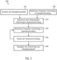
- Fig. 2 shows a flow diagram of an embodiment of a method for controlling the tempering device based on a transfer time of the preforms from the storage device to the transport device. This method can be carried out with the system according to any of the methods associated with Figure 1 described embodiments.
- the method first comprises determining a desired transfer time of preforms from the storage device to the transport device.
- This transfer time can be based, for example, on a break or production interruption of the manufacturing machine 101 (see Fig. 1 ) or be determined based on a gap in the flow of preforms in the transport device 103.
- the transfer time can also be set recurringly at fixed intervals (for example, every 30 minutes or every hour or every two hours) or can be determined as needed depending on the fill level of the storage device, for example to avoid the storage device becoming overfilled. Setting the transfer time according to the time of day (for example, depending on the electricity costs of external power sources already discussed or an expected power surplus of these external power sources) is also conceivable.
- the temperature of the preforms in the transport device in particular at the transfer point (see Fig. 1 ) can be determined.
- a target temperature of the preforms in the storage device can be determined by the control unit 180.
- the target temperature can be set (particularly but not exclusively in the case of orderly storage of the preforms in the storage device) for all or only a real subset of the preforms in the storage device (for example, a number of preforms that can be fed to the transport device during a production interruption of the manufacturing machine of a certain duration).
- the target temperature will usually be greater than, but at most equal to, the temperature of the preforms in the transport device (for example, at the transfer point) and can be determined by the control unit not only as a function of the specific transfer time and/or the specific temperature of the preforms in the transport device, but can also be based, for example, on further information available to the control unit, such as an ambient temperature or an expected heat loss of the preforms after leaving the storage device.
- the temperature control device 205 can then be controlled in such a way that the preforms (either all preforms or the partial quantity) are heated to the target temperature.
- the temperature control device can be controlled in step 205, for example, such that it can heat the preforms or the partial quantity to the target temperature within the time still available until the transfer time. This can be ensured either by the control unit controlling the temperature control device to deliver a predetermined amount of heat per unit of time or by a control loop.
- This control loop can include, in step 204, first determining a temperature of the preforms or the partial quantity in the storage device and optionally comparing this temperature with the target temperature.
- the control unit can then determine how much heat needs to be transferred to the preforms or the partial batch in this time to heat them to the target temperature.
- the temperature control device can then be controlled based on this.
- the temperature of the preforms or the partial quantity in the storage device can be determined again and, by checking the temperature of the preforms, the temperature control device can be further controlled in order to, if necessary, achieve a faster or slower heating of the preforms or the partial quantity.
- increased heat output from the temperature control device may be necessary to heat the preforms or the partial quantity in the storage device to the desired temperature within the specified time until the transfer point. This can be taken into account by the control loop described.
- the preforms or a subset of preforms can be transferred to the transport device at the transfer time (206).
- the storage device will be empty after the transfer is complete or will still contain preforms. In the latter case, it can be provided that the next time preforms are to be transferred to the transport unit again, the remaining preforms and then any preforms newly fed to the storage device in the meantime will be heated by the temperature control device. This keeps the downtime of preforms in the storage device as short as possible.
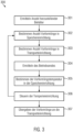
- Fig. 3 shows a further embodiment of a method for controlling the tempering device and transferring the preforms to the transport device for producing containers from these preforms.
- an operating end of the production machine see Fig. 1 .
- a certain number of containers are to be produced simultaneously.
- method 300 begins in step 301 with a determination of the number of containers to be produced.
- This number of containers to be produced can, for example, be a remaining number of containers to be produced. For example, if a total number of 150,000 containers is required for an order, and 100,000 containers have been produced so far, the production of an additional 50,000 containers is required.
- the number of preforms in the storage device and the number of preforms in the transport device can be determined in steps 302 and 303. Based on this number, it can be determined whether further preforms must be produced by the production machine. If the total number of preforms in the storage device and the transport device according to steps 302 and 303 is, for example, 25,000, then the production machine still needs to produce a further 25,000 preforms.
- steps 302 and 303 are shown one after the other here, it is also conceivable that these steps can be carried out simultaneously or in a reversed order.
- an end of operation of the production machine is then determined based on the number of containers to be produced and/or the number of preforms in the storage device and/or the number of preforms in the transport device.
- This end of operation defines when the production machine stops producing preforms. This can either be a complete end of operation (i.e., the point in time at which the production machine has produced all of the containers to be produced) or an operating break (for example, after producing a certain subset of the number of containers to be produced), after which the production machine produces additional preforms. Several such operating breaks can be provided until the number of containers to be produced is reached.
- the time until this end of operation can, for example, be specified as a multiple of an operating cycle, where an operating cycle comprises exactly one production cycle of the production machine.
- the time until the end of operation can also be represented as a time interval (e.g., minutes or hours).
- the temperature control device can then be controlled in step 306 so that the preforms in the storage device have a desired temperature (target temperature) upon reaching the end of operation.
- target temperature target temperature
- the temperature control device can then be controlled in step 306 so that the preforms in the storage device have a desired temperature (target temperature) upon reaching the end of operation.
- target temperature target temperature
- the Fig. 2 The temperature of the preforms in the storage device can be determined in order to then control the temperature control unit based on this.
- steps 302 to 306 are carried out again in the form of a control loop, wherein the number of preforms in the storage device and the remaining number of preforms in the transport device are determined at regular intervals in order to determine the end of operation and based on this and optionally the preform temperatures of the storage devices, the controller controls the temperature control devices.
- step 307 upon reaching the end of operation and/or after the transport device has been emptied to the transfer point, the preforms are transferred from the storage device to the transport device, wherein they then have the desired temperature.
- the target temperature of the preforms can be determined, for example, based on the method of Fig. 2 can be determined.
Landscapes
- Engineering & Computer Science (AREA)
- Manufacturing & Machinery (AREA)
- Mechanical Engineering (AREA)
- Physics & Mathematics (AREA)
- Thermal Sciences (AREA)
- Blow-Moulding Or Thermoforming Of Plastics Or The Like (AREA)
Applications Claiming Priority (1)
| Application Number | Priority Date | Filing Date | Title |
|---|---|---|---|
| DE102023129371.0A DE102023129371A1 (de) | 2023-10-25 | 2023-10-25 | Anlage zum Herstellen von Behältern aus Vorformlingen |
Publications (1)
| Publication Number | Publication Date |
|---|---|
| EP4545271A1 true EP4545271A1 (fr) | 2025-04-30 |
Family
ID=91959506
Family Applications (1)
| Application Number | Title | Priority Date | Filing Date |
|---|---|---|---|
| EP24189451.8A Pending EP4545271A1 (fr) | 2023-10-25 | 2024-07-18 | Installation de fabrication de récipients à partir de préformes |
Country Status (4)
| Country | Link |
|---|---|
| US (1) | US20250135709A1 (fr) |
| EP (1) | EP4545271A1 (fr) |
| CN (1) | CN119871853A (fr) |
| DE (1) | DE102023129371A1 (fr) |
Citations (7)
| Publication number | Priority date | Publication date | Assignee | Title |
|---|---|---|---|---|
| EP0856392A2 (fr) * | 1997-01-29 | 1998-08-05 | Matteo Zoppas | Procédé et dispositif pour la fabrication de récipients en matière thermoplastique |
| EP0813949B1 (fr) * | 1996-06-18 | 2002-04-24 | Husky Injection Molding Systems Ltd. | Système de conditionnement et de stockage pour des préformes, procédé et préformes obtenues |
| EP2052842A1 (fr) * | 2007-10-23 | 2009-04-29 | Glauco E. Curetti | Processus et système de production d'un conteneur de polymère |
| DE102010049404A1 (de) * | 2010-10-26 | 2012-04-26 | Krones Aktiengesellschaft | Vorrichtung und Verfahren zum Herstellen von Kunststoffbehältnissen |
| DE102011053180A1 (de) * | 2011-09-01 | 2013-03-07 | Krones Aktiengesellschaft | Anlage und Verfahren zum Herstellen von Kunststoffbehältnissen |
| DE102012101114A1 (de) * | 2012-02-14 | 2013-08-14 | Krones Ag | Vorrichtung zum Bereitstellen von Verbrauchsmaterial |
| US20220063173A1 (en) * | 2020-08-27 | 2022-03-03 | Krones Ag | Method and apparatus for producing plastic preforms and plastic containers with thermal preform storage |
Family Cites Families (8)
| Publication number | Priority date | Publication date | Assignee | Title |
|---|---|---|---|---|
| US4140464A (en) * | 1977-06-13 | 1979-02-20 | Emhart Industries, Inc. | Machine system for formation of molecularly oriented plastic bottles |
| DE10121160A1 (de) * | 2001-04-30 | 2002-10-31 | Sig Corpoplast Gmbh & Co Kg | Verfahren und Vorrichtung zur Temperierung von Vorformlingen |
| DE102009040559A1 (de) * | 2009-09-08 | 2011-03-10 | Krones Ag | Verfahren und Vorrichtung zum Blasformen von Behältern |
| DE102010021446A1 (de) * | 2010-05-25 | 2011-12-01 | Krones Ag | Verfahren und Vorrichtung zur Temperierung von Vorformlingen |
| DE102014010283A1 (de) * | 2014-07-13 | 2016-01-14 | Khs Corpoplast Gmbh | Verfahren und Blasformungsmaschine zur blasformenden Herstellung von zumindest bereichsweise sterilen Behältern |
| FR3062335B1 (fr) * | 2017-07-21 | 2021-03-19 | Sidel Participations | Procede de maintenance d'une installation de formage de recipients, incluant une procedure de resynchronisation |
| CN114787041A (zh) * | 2019-12-04 | 2022-07-22 | 大日本印刷株式会社 | 盖体杀菌装置以及内容物填充系统 |
| JP7828890B2 (ja) * | 2020-07-17 | 2026-03-12 | 日精エー・エス・ビー機械株式会社 | 樹脂製成形物の情報管理方法、樹脂製容器の製造方法、樹脂製成形物の情報管理装置およびブロー成形装置 |
-
2023
- 2023-10-25 DE DE102023129371.0A patent/DE102023129371A1/de active Pending
-
2024
- 2024-07-18 EP EP24189451.8A patent/EP4545271A1/fr active Pending
- 2024-10-24 US US18/925,584 patent/US20250135709A1/en active Pending
- 2024-10-24 CN CN202411493026.4A patent/CN119871853A/zh active Pending
Patent Citations (7)
| Publication number | Priority date | Publication date | Assignee | Title |
|---|---|---|---|---|
| EP0813949B1 (fr) * | 1996-06-18 | 2002-04-24 | Husky Injection Molding Systems Ltd. | Système de conditionnement et de stockage pour des préformes, procédé et préformes obtenues |
| EP0856392A2 (fr) * | 1997-01-29 | 1998-08-05 | Matteo Zoppas | Procédé et dispositif pour la fabrication de récipients en matière thermoplastique |
| EP2052842A1 (fr) * | 2007-10-23 | 2009-04-29 | Glauco E. Curetti | Processus et système de production d'un conteneur de polymère |
| DE102010049404A1 (de) * | 2010-10-26 | 2012-04-26 | Krones Aktiengesellschaft | Vorrichtung und Verfahren zum Herstellen von Kunststoffbehältnissen |
| DE102011053180A1 (de) * | 2011-09-01 | 2013-03-07 | Krones Aktiengesellschaft | Anlage und Verfahren zum Herstellen von Kunststoffbehältnissen |
| DE102012101114A1 (de) * | 2012-02-14 | 2013-08-14 | Krones Ag | Vorrichtung zum Bereitstellen von Verbrauchsmaterial |
| US20220063173A1 (en) * | 2020-08-27 | 2022-03-03 | Krones Ag | Method and apparatus for producing plastic preforms and plastic containers with thermal preform storage |
Also Published As
| Publication number | Publication date |
|---|---|
| CN119871853A (zh) | 2025-04-25 |
| DE102023129371A1 (de) | 2025-04-30 |
| US20250135709A1 (en) | 2025-05-01 |
Similar Documents
| Publication | Publication Date | Title |
|---|---|---|
| EP2565012B1 (fr) | Installation et procédé de fabrication de récipients en plastique | |
| EP2390082B1 (fr) | Procédé et dispositif de commande et/ou réglage de température d'un dispositif de chauffage pour préformes | |
| DE69712130T2 (de) | Vorformlingkonditionierungs- und Speichersystem, Verfahren und dabei hergestellte Vorform | |
| EP1837157A2 (fr) | Machine à soufflage et procédé de fabrication de bouteilles ou de corps creux analogues | |
| DE3886076T3 (de) | Vorrichtung zum Herstellen von hohlen Artikeln aus Kunststoff. | |
| DE69525985T2 (de) | Vorrichtung und Verfahren zum Spritzstreckblasfromen | |
| EP2125583B1 (fr) | Installation de traitement de bouteilles | |
| EP3960423B1 (fr) | Procédé et dispositif de fabrication de préformes en matière plastique et de récipients en matière plastique comportant un dispositif de stockage thermique de préformes | |
| DE102010021446A1 (de) | Verfahren und Vorrichtung zur Temperierung von Vorformlingen | |
| DE102015209367A1 (de) | Behälterbehandlungsanlage | |
| EP3370935B1 (fr) | Procédé et appareil pour fabriquer un article moulé par rotation | |
| EP2386403B1 (fr) | Parcours de chauffage et dispositif de manipulation pour préformes | |
| EP4209327B1 (fr) | Dispositif et procédé de chauffage d'ébauches en plastique au moyen d'une détection de température à résolution spatiale | |
| EP2441563B1 (fr) | Dispositif et procédé de fabrication de récipients en plastique dotés d'un arrêt de station variable | |
| DE69804456T2 (de) | Einstufiges verfahren mit hoher produktivität und vorrichtung zum herstellen von behältern aus kunststoff | |
| DE102012102357A1 (de) | Preformtransport mit Auswurfmöglichkeit | |
| DE102012101915A9 (de) | Heizvorrichtung und Verfahren zum Temperieren von Vorformlingen | |
| DE102012106600A1 (de) | Schrumpfvorrichtung mit optimiertem Energiemanagement | |
| EP4545271A1 (fr) | Installation de fabrication de récipients à partir de préformes | |
| EP4067049B1 (fr) | Dispositif de formage de préformes en matière plastique en des récipients en matière plastique pourvu d'entraînements découplés | |
| DE102012102356A1 (de) | Vorrichtung zum Erwärmen von Kunststoffvorformlingen mit teilweise Wiederverwendbarkeit von Kunststoffvorformlingen | |
| EP4494839A1 (fr) | Installation de traitement de récipients pour la fabrication et le traitement de préformes | |
| DE102024119901A1 (de) | Anlage zum Herstellen und Behandeln von Behältern | |
| DE102008015169A1 (de) | Verschlusselement für eine Platte eines Transportelements für einen Vorformling, Verfahren und Verwendung | |
| WO2025017119A1 (fr) | Système de traitement de récipients pour le traitement de récipients |
Legal Events
| Date | Code | Title | Description |
|---|---|---|---|
| PUAI | Public reference made under article 153(3) epc to a published international application that has entered the european phase |
Free format text: ORIGINAL CODE: 0009012 |
|
| STAA | Information on the status of an ep patent application or granted ep patent |
Free format text: STATUS: THE APPLICATION HAS BEEN PUBLISHED |
|
| AK | Designated contracting states |
Kind code of ref document: A1 Designated state(s): AL AT BE BG CH CY CZ DE DK EE ES FI FR GB GR HR HU IE IS IT LI LT LU LV MC ME MK MT NL NO PL PT RO RS SE SI SK SM TR |
|
| STAA | Information on the status of an ep patent application or granted ep patent |
Free format text: STATUS: REQUEST FOR EXAMINATION WAS MADE |
|
| STAA | Information on the status of an ep patent application or granted ep patent |
Free format text: STATUS: EXAMINATION IS IN PROGRESS |
|
| 17P | Request for examination filed |
Effective date: 20251027 |
|
| 17Q | First examination report despatched |
Effective date: 20251107 |