EP4545319A2 - Manuelles rollstuhlantriebssystem - Google Patents
Manuelles rollstuhlantriebssystem Download PDFInfo
- Publication number
- EP4545319A2 EP4545319A2 EP25164197.3A EP25164197A EP4545319A2 EP 4545319 A2 EP4545319 A2 EP 4545319A2 EP 25164197 A EP25164197 A EP 25164197A EP 4545319 A2 EP4545319 A2 EP 4545319A2
- Authority
- EP
- European Patent Office
- Prior art keywords
- drive wheel
- mounting
- clamp
- wheelchair
- manual wheelchair
- Prior art date
- Legal status (The legal status is an assumption and is not a legal conclusion. Google has not performed a legal analysis and makes no representation as to the accuracy of the status listed.)
- Granted
Links
Images



Classifications
-
- A—HUMAN NECESSITIES
- A61—MEDICAL OR VETERINARY SCIENCE; HYGIENE
- A61G—TRANSPORT, PERSONAL CONVEYANCES, OR ACCOMMODATION SPECIALLY ADAPTED FOR PATIENTS OR DISABLED PERSONS; OPERATING TABLES OR CHAIRS; CHAIRS FOR DENTISTRY; FUNERAL DEVICES
- A61G5/00—Chairs or personal conveyances specially adapted for patients or disabled persons, e.g. wheelchairs
- A61G5/04—Chairs or personal conveyances specially adapted for patients or disabled persons, e.g. wheelchairs motor-driven
- A61G5/047—Chairs or personal conveyances specially adapted for patients or disabled persons, e.g. wheelchairs motor-driven by a modular detachable drive system
-
- A—HUMAN NECESSITIES
- A61—MEDICAL OR VETERINARY SCIENCE; HYGIENE
- A61G—TRANSPORT, PERSONAL CONVEYANCES, OR ACCOMMODATION SPECIALLY ADAPTED FOR PATIENTS OR DISABLED PERSONS; OPERATING TABLES OR CHAIRS; CHAIRS FOR DENTISTRY; FUNERAL DEVICES
- A61G5/00—Chairs or personal conveyances specially adapted for patients or disabled persons, e.g. wheelchairs
- A61G5/02—Chairs or personal conveyances specially adapted for patients or disabled persons, e.g. wheelchairs propelled by the patient or disabled person
- A61G5/027—Chairs or personal conveyances specially adapted for patients or disabled persons, e.g. wheelchairs propelled by the patient or disabled person by using auxiliary detachable mechanisms
-
- B—PERFORMING OPERATIONS; TRANSPORTING
- B60—VEHICLES IN GENERAL
- B60G—VEHICLE SUSPENSION ARRANGEMENTS
- B60G2300/00—Indexing codes relating to the type of vehicle
- B60G2300/24—Wheelchairs
Definitions
- This invention relates in general to manual wheelchairs.
- this invention relates to auxiliary propulsion devices for manual wheelchairs.
- the invention refers to a propulsion system for a manual wheelchair according to the preamble of claim 1.
- Manual wheelchairs are cost effective mobility aids, many of which are foldable for easy transport. Manual wheelchairs generally rely either on an attendant or the user for propulsion power. Users with sufficient upper body strength can propel a manual wheelchair for some distance but fatigue is an inevitable outcome if the travel distance is long.
- Devices designed to provide auxiliary motive power to a manual wheelchair are known. These devices are either incorporated into the large, hand-rim, drive wheels or provided as add-on units typically attached to structural elements of the manual wheelchair, such as frames or rear axle tubes or mounts.
- the auxiliary propulsion device is a propulsion system for a manual wheelchair where the system includes a mounting clamp and a propulsion drive unit.
- the propulsion drive unit includes a drive wheel assembly and a support suspension.
- the support suspension is configured to provide linear movement of the drive wheel and drive hub assembly relative to the manual wheelchair.
- the support suspension of the propulsion system includes a linear bearing and slide member assembly having at least one linear bearing and a slide member for accommodating the linear movement of the drive wheel assembly.
- the support suspension also includes a resilient suspension member that provides a tractive effort force to the drive wheel.
- the drive wheel assembly is supported on a carriage that is attached to one of the at least one linear bearing or the slide member and having a suspension mount in contact with the resilient suspension member.
- the mounting clamp is connected to the other of the linear bearing or the slide member.
- actuator provides selective linear movement of the carriage between a drive position where the drive wheel contacts the ground and a stowed position where the drive wheel is out of contact with the ground.
- the mounting clamp is selectively engaged to a mounting block that is attached to the other of the at least one linear bearing or slide member.
- the mounting block has a clamp interface that engages the mounting clamp.
- the mounting clamp includes a mounting cavity having a lead-in wall and a mounting slot.
- the lead-in wall is shaped to guide a portion of the clamp interface into the mounting slot.
- the clamp interface includes a locating tab that is configured to seat into the mounting slot.
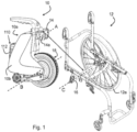
- the propulsion system 10 includes a propulsion unit 10a and a clamp 14 that is configured to attach to a structural member of the wheelchair 12, such as a cross-member, a camber tube, or axle tube 16.
- the clamp 14 has at least one aperture 14a that defines a mounting axis A.
- the propulsion system 10 further includes a drive wheel assembly 18, illustrated as a tire or rather drive wheel 18a and hub motor assembly 18b, though other drive systems such as a motorized pinch-roller or friction drive, belt or chain drive, shaft drive, and the like may be used.
- the drive wheel assembly 18 defines a wheel rotational axis B through the hub rotational centerline and an associated tire contact patch, i.e., the area of the tire in contact with a support surface such as the ground.
- the wheelchair 12 includes drive wheels 12a, though only one wheel is illustrated two spaced-apart drive wheels are known, that define a rotational axis C and an associated tire contact patch.
- the propulsion system 10 includes a mounting block 20 having a slide mounting body 20a and a clamp interface 20b.
- the slide mounting body 20a is configured to attach to one of at least one slide bearing 22 or a mating slide 24, configured as a slide bar, track or other suitable linear motion structure.
- these bearings 22 may be any suitable rolling or sliding element including bearings, bushings, or other elements conducive to supporting linear motion.
- the slide bar 24 includes a suspension reaction mount 24a.
- the mounting block 20 is connected to an actuator 26, illustrated within a cavity 28 of the slide mounting body 20a, at a first or lower end 26a of the actuator 26.
- the actuator 26 selectively engages a carriage 30 at a second or upper end 26b of the actuator 26.
- the carriage 30 has a mounting plate 30a that is proximate to and configured to attach to the other of the at least one slide bearing 22 or the mating slide 24 such that the carriage 30 is linearly moveable relative to the mounting block 20.
- the carriage 30 has a drive wheel fork 30b at a distal end that supports the drive wheel assembly 18 for rotation.
- the carriage 30 further includes a slide mount 30c that supports one of the slide bar 24 or the at least one slide bearing 22.
- the suspension reaction mount 24a is attached to the slide bar 24 and extends into the actuator cavity 28 and is configured to be contacted by the actuator second end 26b when the actuator 26 is extended.
- the suspension reaction mount 24a may be formed integrally with the slide bar 24 or the carriage 30 if desired.
- the actuator 26 selectively moves the carriage 30 and the drive wheel 18 relative to the mounting block 20 between a use position, where the drive wheel is in contact with the ground, and a stowed position, where the drive wheel is moved out of contact with the ground.
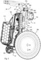
- Fig. 3 illustrates the actuator 26 in the use position where the second end 26b is retracted away from the suspension reaction mount 24a.
- the carriage 30 is shown in an articulated position where the suspension reaction mount 24a has compressed a resilient suspension member such as during an obstacle traversal maneuver by the propulsion system 10.
- the carriage 30 includes at least one kickstand mount 30d, illustrated as extending from the drive wheel fork 30b, for supporting a kickstand 32.
- the kickstand 32 supports the system 10 in a free-standing configuration, as shown in Fig. 7B , when detached from the wheelchair 12 or the clamp 14.
- the illustrated kickstand 32 includes a kickstand fork 34 pivotally mounted to the kickstand mount 30d at a first end and supporting at least one wheel 36 at a second end.
- Two wheels 36 illustrated as Omni style or Mecanum-style wheels having lateral roller elements, are shown mounted on opposing arms of the kickstand fork 34.
- the Omni-style wheels accommodate lateral movement of the propulsion system 10, making attachment or detachment of the unit easier by a user from a seated position.
- the fork 34 is held out of contact with the ground or support surface, as shown in Fig. 7A , by a spring 38.
- the kickstand 32 is configured to clear or pivot away from irregularities encountered during travel in order to prevent force transfers to the wheelchair 12 that can cause unintended deviations in the desired travel direction.
- the slide mounting body 20a supports a resilient suspension member in the form of a suspension spring 40, shown as a coil compression spring though other resilient elements may be used.
- the suspension spring 40 applies a force to the carriage 30 and drive wheel assembly 18, through the suspension reaction mount 24a, that is sufficient to provide traction to propel the wheelchair 12.
- the suspension spring 40 in contact with the suspension reaction mount 24a, compresses and extends as the drive wheel system 18 moves over irregular surfaces to maintain ground contact.
- a handle 42 is secured to the slide mounting body 20a.
- the handle 42 is shown having an upper body 42a and a lower body 42b.
- the lower body 42b includes a spring seat 44 that contacts the suspension spring 40.
- the spring seat 44 may alternatively be part of the mounting body 20a.
- the upper body 42a supports and/or houses at least a portion of a latching mechanism, shown generally at 46 of Fig. 4B , which will be explained in detail below.
- a latching mechanism shown generally at 46 of Fig. 4B , which will be explained in detail below.
- the slide 24 and slide bearings 22 transfer the tractive force of the drive wheel to the clamp 14 and wheelchair axle or cross member 16 thus moving the wheelchair 12 forward.
- the linear motion of the slide members 24 and 22 permits the drive wheel 18a to articulate relative to terrain irregularities and permits the actuator 26 to move the drive wheel 18a out of contact with the ground if only manual propulsion is desired. This permits a user to easily reduce drag from the propulsion unit 10a in manual mode operation without removing the unit.
- the latching mechanism 46 is supported by the handle 42 and the mounting block 20.
- the latching mechanism 46 includes an actuation lever 48 that is pivotally supported by a pin 48a on the handle lower body 42b and resiliently held in a ready position enabling release of the propulsion unit 10a portion of the propulsion system 10 from the clamp 14.
- the actuation lever 48 has an actuation cam face 48b that contacts a latch cam face 50a of a latch hook 50.
- the latch hook 50 as illustrated, is pivotally supported on the mounting block 20 by a pin 50b and resiliently held in an engaged position where a hook end 50c is positioned to hold the propulsion unit 10a fixed to the clamp 14.
- the hook end 50c is movable relative to the mounting block to permit securement of the propulsion unit 10a to the clamp 14 without operating the actuation lever 48. This permits easier attachment of the unit 10a by a seated user.
- the clamp 14 as shown in Figs. 4A and 4B , includes a mounting cavity 14b having a lead-in wall 14c terminating in a mounting slot 14d.
- the mating clamp interface 20b of the mounting block 20 includes a locating tab or tongue 20c that is configured to locate and seat within the mounting slot 14d.
- the mounting cavity 14b can function as a funnel or chute to guide the locating tab 20c into engagement with the mounting slot 14d.
- the propulsion unit 10a may be free-standing with the aid of the kickstand 32 such that the locating tab 20c is aimed toward the clamp 14 mounted on the axle or camber tube 16 of the manual wheelchair 12.
- the actuator 26 When the actuator 26 is contracted, the mounting block 20 is raised relative to the carriage 30 by extension of the suspension spring 40 toward its free state length.
- the locating tab 20c may be sufficiently elevated to enter the mounting cavity 14b as the propulsion unit 10a rests on the kickstand 32.
- the unit 10a When the unit 10a is aligned relative to the clamp 14, the wheelchair may be rolled backwards until the locating tab 20c enters the mounting cavity 14b. In other configurations, the unit may need to be elevated by the user through the handle 42.
- the actuator 26 may be extended to draw the locating tab 20c into the mounting slot 14d.
- the hook end 50c of the latch hook 50 engages a latching boss 14e of the clamp 14 to secure the propulsion unit 10a to the clamp 14 and the wheelchair 12.
- the latching mechanism 46 may be activated by moving the actuation lever 48 into the handle 42. This causes the lever 48 to pivot about pin 48a causing the actuation cam face 48b to move the latch cam face 50a toward the clamp 14.
- the latch hook 50 pivots about the latch pivot pin 50b causing the hook end 50c to disengage from the latching boss 14e. If the unit 10a is loaded against the ground with the suspension spring 40 compressed, the force exerted by the spring may assist in extracting the clamp interface 20b from the mounting cavity 14b as the mounting block 20 is moved by the spring force.
- the latch hook 50 may be more easily pivoted and the unit 10a can be lifted from the mounting cavity 14b
- the actuator 26 may include a linkage (not shown) that releases the latch hook 50 when the actuator 26 is extended beyond the length necessary to lift the wheel off of the ground.
- the actuator 26 may be directly or indirectly connected to the latch hook 50 or may actuate the lever 48 in order to provide remote or automated actuation.
- the clamping axis A is coincident with the axle tube axis C. Because the drive wheel axis B extends toward the clamping axis A, the drive wheel tire contact patch is moved close to or coincident with the tire patch of the wheelchair drive wheel 12a. This results in the system 10 being contained within an envelope defined by the wheelchair 12, including the drive wheels 12a.
- the envelope can be defined by a line generally tangent to an outer diameter of the wheelchair drive wheel and may represent a wall or other external structure abutting the wheelchair drive wheel.
- This packaging permits a seated user to operate the manual wheelchair 12 in the usual manner, including being able to manually back the wheelchair against a wall, curb, or other structure and also lean the wheelchair against a wall, which is a common resting position providing the weight distribution benefits of a reclined, seated position to reduce prolonged seated skin conditions.
- the close proximity of the drive wheel contact patches is primarily enabled by the use of sliding suspension members instead of pivoting suspension members.
- This provides the ability to package the moving components in a compact envelope. In one embodiment, this permits the unit to be mounted in a rearward position that is more easily accessible by the seated user for attaching and disconnecting the unit fostering a greater sense of independence.
- the propulsion system 10 may be mounted from the front side of the wheelchair and extend toward the rear.
- the propulsion unit drive wheel tire patch is close to or in line with the wheelchair drive wheel tire patch, the moment created by the offset is minimized. This reduces the cause of tire scrubbing and permits easier turning and maneuvering of the wheelchair. Since the operating basis of the wheelchair is manual in nature, maneuvering is based on relative speed or rotation of one drive wheel 12a relative to the other spaced- apart drive wheel 12a.
- maneuvering is based on relative speed or rotation of one drive wheel 12a relative to the other spaced- apart drive wheel 12a.
- the weight of the unit is brought closer to the center of gravity of the wheelchair and seated user which reduces tipping or instability sensations. This location also can take advantage of the weight over the wheelchair drive wheels to improve tractive effort of the propulsion drive wheel 18a.
- the propulsion system 10 includes a controller 100 containing electronics necessary to operate the propulsion unit for drive control, suspension control, and/or latch control.
- the controller 100 and other components of the propulsion system may be enclosed in a housing 10b, though such is not required.
- the propulsion unit 10 also includes an energy source, illustrated as a battery pack 110 and a battery housing 112.
- the controller 100 may include all of the necessary sensors within the controller or may receive signals from remote sensors for processing.
- the actuator 26 may be configured as an electrically driven actuator and rely on a current measurement to detect end of travel positioning. Such a sensor and its associated measurement may be provided on the controller 100. Alternatively, the actuator 26 may rely on a proximity switch or load cell to detect the end of travel position which may be remote mounted from the controller 100 and attached to the actuator or a supporting structure.
- a first version is shown in Figs. 8A-8C and 11.
- This version identified as Embodiment 2
- the carriage rollers are supported and guided by slots formed in the housing.
- a mounting bolt extends through the slot to slidably secure the carriage roller blocks to the housing.
- the slots are formed in generally parallel raised portions that engage corresponding recesses formed in the carriage roller blocks.
- the power drive wheel with hub motor is mounted in a linearly movable support housing using linear bearings.
- the linear bearings engage a slide track having parallel grooves that support and guide the linear bearings.
Landscapes
- Health & Medical Sciences (AREA)
- Life Sciences & Earth Sciences (AREA)
- Animal Behavior & Ethology (AREA)
- General Health & Medical Sciences (AREA)
- Public Health (AREA)
- Veterinary Medicine (AREA)
- Handcart (AREA)
- Motorcycle And Bicycle Frame (AREA)
Applications Claiming Priority (3)
| Application Number | Priority Date | Filing Date | Title |
|---|---|---|---|
| US201862784015P | 2018-12-21 | 2018-12-21 | |
| PCT/US2019/068377 WO2020132685A1 (en) | 2018-12-21 | 2019-12-23 | Manual wheel chair propulsion system |
| EP19899962.5A EP3897500B1 (de) | 2018-12-21 | 2019-12-23 | Antriebssystem für manuellen rollstuhl |
Related Parent Applications (1)
| Application Number | Title | Priority Date | Filing Date |
|---|---|---|---|
| EP19899962.5A Division EP3897500B1 (de) | 2018-12-21 | 2019-12-23 | Antriebssystem für manuellen rollstuhl |
Publications (3)
| Publication Number | Publication Date |
|---|---|
| EP4545319A2 true EP4545319A2 (de) | 2025-04-30 |
| EP4545319A3 EP4545319A3 (de) | 2025-07-09 |
| EP4545319B1 EP4545319B1 (de) | 2026-04-01 |
Family
ID=71100955
Family Applications (2)
| Application Number | Title | Priority Date | Filing Date |
|---|---|---|---|
| EP19899962.5A Active EP3897500B1 (de) | 2018-12-21 | 2019-12-23 | Antriebssystem für manuellen rollstuhl |
| EP25164197.3A Active EP4545319B1 (de) | 2018-12-21 | 2019-12-23 | Manuelles rollstuhlantriebssystem |
Family Applications Before (1)
| Application Number | Title | Priority Date | Filing Date |
|---|---|---|---|
| EP19899962.5A Active EP3897500B1 (de) | 2018-12-21 | 2019-12-23 | Antriebssystem für manuellen rollstuhl |
Country Status (6)
| Country | Link |
|---|---|
| US (2) | US12115110B2 (de) |
| EP (2) | EP3897500B1 (de) |
| JP (1) | JP2022516037A (de) |
| AU (1) | AU2019404594B2 (de) |
| ES (1) | ES3035133T3 (de) |
| WO (1) | WO2020132685A1 (de) |
Families Citing this family (6)
| Publication number | Priority date | Publication date | Assignee | Title |
|---|---|---|---|---|
| US11529274B2 (en) * | 2018-04-27 | 2022-12-20 | Roda Futura, Llc | Removable power assist for manual wheelchair |
| US20230072204A1 (en) * | 2021-09-09 | 2023-03-09 | Juliana T. Iacono | Motorized wheel system |
| US20230190546A1 (en) * | 2021-12-20 | 2023-06-22 | Permobil, Inc. | Front add-on for a wheelchair |
| DE102022100043A1 (de) | 2022-01-03 | 2023-07-06 | Aat Alber Antriebstechnik Gmbh | Antriebseinrichtung für einen Rollstuhl |
| DE202022100039U1 (de) | 2022-01-03 | 2022-01-11 | Aat Alber Antriebstechnik Gmbh | Antriebseinrichtung für einen Rollstuhl |
| ES3017868T3 (en) | 2022-07-07 | 2025-05-13 | Permobil Ab | Powered midwheel drive wheelchair with standing capability |
Family Cites Families (15)
| Publication number | Priority date | Publication date | Assignee | Title |
|---|---|---|---|---|
| US3387681A (en) * | 1966-02-14 | 1968-06-11 | Rodney R. Rabjohn | Power operated wheel chair |
| FR2675688A1 (fr) * | 1991-04-26 | 1992-10-30 | Poirier Ets | Vehicule individuel utilisable en version manuelle ou motorisee, notamment fauteuil roulant ou tricycle. |
| US5222567A (en) * | 1991-04-26 | 1993-06-29 | Genus Inc. | Power assist device for a wheelchair |
| US5351774A (en) | 1992-06-02 | 1994-10-04 | Quickie Designs Inc. | Powered wheelchair with a detachable power drive assembly |
| US5651422A (en) * | 1994-04-22 | 1997-07-29 | The Center For Innovative Technology | Universal-fit, quick-connect power drive/steer attachment for wheelchair |
| DE19539487A1 (de) * | 1995-10-24 | 1997-04-30 | Alber Ulrich Gmbh | Antriebs- und Bremshilfsvorrichtung für Rollstühle |
| DE19935506B4 (de) * | 1999-07-28 | 2009-07-09 | Georg Binnen | Elektromotorisch angetriebenes Zuggerät für Rollstühle |
| EP1927331A1 (de) * | 2006-11-29 | 2008-06-04 | ZMI Electronics Ltd. | Hilfsantriebsvorrichtung für einen Rollstuhl |
| US8960340B2 (en) * | 2009-05-27 | 2015-02-24 | Patrick Tallino | Power add-on device for manual wheelchair |
| US8430189B2 (en) * | 2009-05-27 | 2013-04-30 | Patrick Tallino | Power add-on device for manual wheelchair |
| GB2481404A (en) * | 2010-06-22 | 2011-12-28 | Wus Tech Co Ltd | Wheelchair with detachable drive means and frame |
| US20120279789A1 (en) * | 2011-05-02 | 2012-11-08 | Bradley Brill | Detachable power drive unit for propelling and steering manual wheelchairs |
| KR101454716B1 (ko) | 2013-02-13 | 2014-10-27 | 계명대학교 산학협력단 | 탈장착 가능한 동력 전달장치 및 이를 장착한 휠체어 |
| US9144525B2 (en) * | 2013-03-14 | 2015-09-29 | Max Mobility, Llc. | Motion assistance system for wheelchairs |
| US9808384B2 (en) | 2013-06-27 | 2017-11-07 | Stephen C. Golden, JR. | Unilateral transition means for adapting a wheelchair |
-
2019
- 2019-12-23 ES ES19899962T patent/ES3035133T3/es active Active
- 2019-12-23 US US17/416,801 patent/US12115110B2/en active Active
- 2019-12-23 JP JP2021536394A patent/JP2022516037A/ja active Pending
- 2019-12-23 AU AU2019404594A patent/AU2019404594B2/en active Active
- 2019-12-23 EP EP19899962.5A patent/EP3897500B1/de active Active
- 2019-12-23 WO PCT/US2019/068377 patent/WO2020132685A1/en not_active Ceased
- 2019-12-23 EP EP25164197.3A patent/EP4545319B1/de active Active
-
2024
- 2024-10-10 US US18/911,362 patent/US20250032331A1/en active Pending
Also Published As
| Publication number | Publication date |
|---|---|
| EP3897500A4 (de) | 2022-09-07 |
| EP3897500B1 (de) | 2025-04-16 |
| JP2022516037A (ja) | 2022-02-24 |
| US12115110B2 (en) | 2024-10-15 |
| ES3035133T3 (en) | 2025-08-29 |
| US20250032331A1 (en) | 2025-01-30 |
| EP4545319B1 (de) | 2026-04-01 |
| EP3897500A1 (de) | 2021-10-27 |
| AU2019404594B2 (en) | 2025-03-20 |
| AU2019404594A1 (en) | 2021-07-22 |
| US20220062076A1 (en) | 2022-03-03 |
| WO2020132685A1 (en) | 2020-06-25 |
| EP4545319A3 (de) | 2025-07-09 |
Similar Documents
| Publication | Publication Date | Title |
|---|---|---|
| US20250032331A1 (en) | Manual Wheelchair Propulsion System | |
| US5291959A (en) | Individual vehicle usable in a manual or a motorized version, in particular a wheelchair or a tricycle | |
| US10675206B2 (en) | Electrically driven wheeled walker | |
| US6766871B2 (en) | Attachment means for attaching a wheelchair to a motorized apparatus | |
| US12582565B2 (en) | Auxiliary drive device for a wheelchair | |
| US4944359A (en) | Vehicle and method of releasably coupling parts of the vehicle together | |
| US4771840A (en) | Articulated power-driven shopping cart | |
| US4811966A (en) | Kerb climbing device | |
| EP3373879B1 (de) | Befestigung für einen rollstuhl | |
| JP2008229329A (ja) | 車いす運搬用車両 | |
| EP3878712B1 (de) | Motorisierte schubkarre | |
| US20250057709A1 (en) | Chair-drive interface assembly, wheelchair and/or drive | |
| JP2024544355A (ja) | 車椅子用の前部アドオンの検出に応答して駆動動作及び性能を調整するシステム | |
| US8096745B2 (en) | Paper roll transport cart | |
| US11311435B2 (en) | Frame for utilization with components of wheelchair | |
| CN222765379U (zh) | 一种轮椅用快速组装牵引车 | |
| JP2020069938A (ja) | 運搬用台車の走行補助装置 | |
| JP2025173147A (ja) | 搬送車 |
Legal Events
| Date | Code | Title | Description |
|---|---|---|---|
| PUAI | Public reference made under article 153(3) epc to a published international application that has entered the european phase |
Free format text: ORIGINAL CODE: 0009012 |
|
| STAA | Information on the status of an ep patent application or granted ep patent |
Free format text: STATUS: THE APPLICATION HAS BEEN PUBLISHED |
|
| AC | Divisional application: reference to earlier application |
Ref document number: 3897500 Country of ref document: EP Kind code of ref document: P |
|
| AK | Designated contracting states |
Kind code of ref document: A2 Designated state(s): AL AT BE BG CH CY CZ DE DK EE ES FI FR GB GR HR HU IE IS IT LI LT LU LV MC MK MT NL NO PL PT RO RS SE SI SK SM TR |
|
| REG | Reference to a national code |
Ref country code: DE Ref legal event code: R079 Free format text: PREVIOUS MAIN CLASS: B60G0011107000 Ipc: A61G0005040000 Ref country code: DE Ref legal event code: R079 Ref document number: 602019083302 Country of ref document: DE Free format text: PREVIOUS MAIN CLASS: B60G0011107000 Ipc: A61G0005040000 |
|
| PUAL | Search report despatched |
Free format text: ORIGINAL CODE: 0009013 |
|
| STAA | Information on the status of an ep patent application or granted ep patent |
Free format text: STATUS: REQUEST FOR EXAMINATION WAS MADE |
|
| AK | Designated contracting states |
Kind code of ref document: A3 Designated state(s): AL AT BE BG CH CY CZ DE DK EE ES FI FR GB GR HR HU IE IS IT LI LT LU LV MC MK MT NL NO PL PT RO RS SE SI SK SM TR |
|
| RIC1 | Information provided on ipc code assigned before grant |
Ipc: B60G 11/107 20060101ALI20250603BHEP Ipc: A61G 5/10 20060101ALI20250603BHEP Ipc: A61G 5/04 20130101AFI20250603BHEP |
|
| 17P | Request for examination filed |
Effective date: 20250613 |
|
| GRAP | Despatch of communication of intention to grant a patent |
Free format text: ORIGINAL CODE: EPIDOSNIGR1 |
|
| STAA | Information on the status of an ep patent application or granted ep patent |
Free format text: STATUS: GRANT OF PATENT IS INTENDED |
|
| INTG | Intention to grant announced |
Effective date: 20251023 |
|
| RIN1 | Information on inventor provided before grant (corrected) |
Inventor name: GREIG, MARK Inventor name: BASHIAN, JEFFEREY Inventor name: ZHOU, DANIEL Inventor name: TRAXINGER, SAMUEL |
|
| GRAS | Grant fee paid |
Free format text: ORIGINAL CODE: EPIDOSNIGR3 |
|
| GRAA | (expected) grant |
Free format text: ORIGINAL CODE: 0009210 |
|
| STAA | Information on the status of an ep patent application or granted ep patent |
Free format text: STATUS: THE PATENT HAS BEEN GRANTED |
|
| AC | Divisional application: reference to earlier application |
Ref document number: 3897500 Country of ref document: EP Kind code of ref document: P |
|
| AK | Designated contracting states |
Kind code of ref document: B1 Designated state(s): AL AT BE BG CH CY CZ DE DK EE ES FI FR GB GR HR HU IE IS IT LI LT LU LV MC MK MT NL NO PL PT RO RS SE SI SK SM TR |
|
| REG | Reference to a national code |
Ref country code: CH Ref legal event code: F10 Free format text: ST27 STATUS EVENT CODE: U-0-0-F10-F00 (AS PROVIDED BY THE NATIONAL OFFICE) Effective date: 20260401 Ref country code: GB Ref legal event code: FG4D |
|
| REG | Reference to a national code |
Ref country code: DE Ref legal event code: R096 Ref document number: 602019083302 Country of ref document: DE |
|
| REG | Reference to a national code |
Ref country code: IE Ref legal event code: FG4D |