EP4545320A1 - Procédé de gestion de suspensions hydrauliques d'un véhicule agricole - Google Patents
Procédé de gestion de suspensions hydrauliques d'un véhicule agricole Download PDFInfo
- Publication number
- EP4545320A1 EP4545320A1 EP24207124.9A EP24207124A EP4545320A1 EP 4545320 A1 EP4545320 A1 EP 4545320A1 EP 24207124 A EP24207124 A EP 24207124A EP 4545320 A1 EP4545320 A1 EP 4545320A1
- Authority
- EP
- European Patent Office
- Prior art keywords
- vehicle
- chamber
- hydraulic
- hydraulic accumulator
- height
- Prior art date
- Legal status (The legal status is an assumption and is not a legal conclusion. Google has not performed a legal analysis and makes no representation as to the accuracy of the status listed.)
- Pending
Links
Images
Classifications
-
- B—PERFORMING OPERATIONS; TRANSPORTING
- B60—VEHICLES IN GENERAL
- B60G—VEHICLE SUSPENSION ARRANGEMENTS
- B60G11/00—Resilient suspensions characterised by arrangement, location or kind of springs
- B60G11/26—Resilient suspensions characterised by arrangement, location or kind of springs having fluid springs only, e.g. hydropneumatic springs
- B60G11/265—Resilient suspensions characterised by arrangement, location or kind of springs having fluid springs only, e.g. hydropneumatic springs hydraulic springs
-
- B—PERFORMING OPERATIONS; TRANSPORTING
- B60—VEHICLES IN GENERAL
- B60G—VEHICLE SUSPENSION ARRANGEMENTS
- B60G17/00—Resilient suspensions having means for adjusting the spring or vibration-damper characteristics, for regulating the distance between a supporting surface and a sprung part of vehicle or for locking suspension during use to meet varying vehicular or surface conditions, e.g. due to speed or load
- B60G17/02—Spring characteristics, e.g. mechanical springs and mechanical adjusting means
- B60G17/04—Spring characteristics, e.g. mechanical springs and mechanical adjusting means fluid spring characteristics
- B60G17/056—Regulating distributors or valves for hydropneumatic systems
- B60G17/0565—Height adjusting valves
-
- B—PERFORMING OPERATIONS; TRANSPORTING
- B60—VEHICLES IN GENERAL
- B60G—VEHICLE SUSPENSION ARRANGEMENTS
- B60G17/00—Resilient suspensions having means for adjusting the spring or vibration-damper characteristics, for regulating the distance between a supporting surface and a sprung part of vehicle or for locking suspension during use to meet varying vehicular or surface conditions, e.g. due to speed or load
- B60G17/015—Resilient suspensions having means for adjusting the spring or vibration-damper characteristics, for regulating the distance between a supporting surface and a sprung part of vehicle or for locking suspension during use to meet varying vehicular or surface conditions, e.g. due to speed or load the regulating means comprising electric or electronic elements
- B60G17/017—Resilient suspensions having means for adjusting the spring or vibration-damper characteristics, for regulating the distance between a supporting surface and a sprung part of vehicle or for locking suspension during use to meet varying vehicular or surface conditions, e.g. due to speed or load the regulating means comprising electric or electronic elements characterised by their use when the vehicle is stationary, e.g. during loading, engine start-up or switch-off
-
- B—PERFORMING OPERATIONS; TRANSPORTING
- B60—VEHICLES IN GENERAL
- B60G—VEHICLE SUSPENSION ARRANGEMENTS
- B60G2202/00—Indexing codes relating to the type of spring, damper or actuator
- B60G2202/10—Type of spring
- B60G2202/15—Fluid spring
- B60G2202/154—Fluid spring with an accumulator
-
- B—PERFORMING OPERATIONS; TRANSPORTING
- B60—VEHICLES IN GENERAL
- B60G—VEHICLE SUSPENSION ARRANGEMENTS
- B60G2300/00—Indexing codes relating to the type of vehicle
- B60G2300/08—Agricultural vehicles
-
- B—PERFORMING OPERATIONS; TRANSPORTING
- B60—VEHICLES IN GENERAL
- B60G—VEHICLE SUSPENSION ARRANGEMENTS
- B60G2400/00—Indexing codes relating to detected, measured or calculated conditions or factors
- B60G2400/25—Stroke; Height; Displacement
- B60G2400/252—Stroke; Height; Displacement vertical
-
- B—PERFORMING OPERATIONS; TRANSPORTING
- B60—VEHICLES IN GENERAL
- B60G—VEHICLE SUSPENSION ARRANGEMENTS
- B60G2400/00—Indexing codes relating to detected, measured or calculated conditions or factors
- B60G2400/50—Pressure
- B60G2400/51—Pressure in suspension unit
- B60G2400/512—Pressure in suspension unit in spring
- B60G2400/5122—Fluid spring
-
- B—PERFORMING OPERATIONS; TRANSPORTING
- B60—VEHICLES IN GENERAL
- B60G—VEHICLE SUSPENSION ARRANGEMENTS
- B60G2500/00—Indexing codes relating to the regulated action or device
- B60G2500/30—Height or ground clearance
-
- B—PERFORMING OPERATIONS; TRANSPORTING
- B60—VEHICLES IN GENERAL
- B60G—VEHICLE SUSPENSION ARRANGEMENTS
- B60G2600/00—Indexing codes relating to particular elements, systems or processes used on suspension systems or suspension control systems
- B60G2600/02—Retarders, delaying means, dead zones, threshold values, cut-off frequency, timer interruption
Definitions
- the present invention relates to the field of agricultural vehicles and in particular to a method of managing the hydraulic suspensions of an agricultural vehicle.
- Agricultural vehicles are often equipped with hydraulic suspensions.
- At least one double-acting hydraulic actuator is provided to raise or lower the vehicle body with respect to the ground.
- To lift the vehicle it is necessary to send oil to the piston chamber and allow the rod chamber to empty, while to lower the vehicle, it is necessary to send oil to the rod chamber and allow the piston chamber to empty.
- the emptying chamber is operationally connected to a hydraulic oil collection tank, from which a hydraulic pump is arranged to draw oil and send it to the filling chamber. Since hydraulic oil is incompressible, in order to dampen ground stress, the pressurized circuit is connected to a hydraulic accumulator.
- the vehicle could start to lift seven seconds after the operator's lifting command.
- the aim of the present invention is to improve the response of the vehicle without compromising the durability of the hydraulic accumulators associated with the chambers of the hydraulic actuator of a vehicle suspension.
- the basic idea of the present invention is to provide a control valve for the connection of the hydraulic accumulator associated with one of the chambers of the hydraulic actuator and to provide for isolating the hydraulic accumulator when, during emptying of the hydraulic accumulator , the height of the vehicle reaches a predetermined threshold, close to the minimum height or the maximum height of the vehicle from the ground.
- the control valve is controlled to isolate the hydraulic accumulator when the height of the vehicle is reduced until it reaches a first predetermined threshold, close to the minimum height of the vehicle from the ground.
- a valve may be provided to control the connection of the hydraulic accumulator associated with the rod chamber and in which the valve is controlled so as to isolate the hydraulic accumulator associated with the rod chamber when the height of the vehicle, by increasing, reaches a second predetermined threshold, close to the maximum height of the vehicle from the ground.
- This advantageously, allows to avoid completely discharging the hydraulic accumulators by having a prompt response when the opposite command is given, for example, lifting after a complete lowering, since the source of hydraulic oil, in the first stages of filling the fully contracted hydraulic chamber of the actuator, is not requested to pressurize also the hydraulic accumulator.
- both hydraulic accumulators are isolated when the first or second predetermined threshold is reached.
- this prevents the accumulator connected to the contracting actuator chamber from being damaged by excessive pressurization.
- the same strategy can be implemented for the accumulator connected to the expanding chamber: for example, if the operator commands the complete lifting of the vehicle, the piston chamber expands completely and the pressure inside can exceed a threshold such as to damage the relevant accumulator.
- the accumulator connected to the piston chamber can also be isolated when the height of the vehicle exceeds a predetermined threshold, so as to prevent it from being damaged.
- the hydraulic accumulators are isolated when the height of the vehicle from the ground is 5 - 10% of the maximum height in the complete lowering phase and 90 - 95% of the maximum height in the complete lifting phase.
- hydraulic accumulators are connected in the range between 5 and 95% (or 10 and 10%) of the maximum height and disconnected outside.
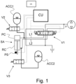
- the adjustable hydraulic suspension system includes a double-acting actuator SA, equipped, as is known, with a first chamber PC and a second chamber RC, opposed to each other and therefore arranged alternately to expand and contract, causing the vehicle to lift or lower.
- the rod chamber contracts, causing the vehicle to lift. Conversely, when the piston chamber contracts and the rod chamber expands, then the vehicle lowers.
- the suspension control system evidently includes a source of pressurized hydraulic oil P, generally a hydraulic pump, arranged to draw oil from a collection tank T.
- a source of pressurized hydraulic oil P generally a hydraulic pump, arranged to draw oil from a collection tank T.
- a control valve V1 allows to alternatively connect the first or second chamber with the source of hydraulic oil P and at the same time respectively the second or first chamber with the collection tank to collect the oil released by the contracting chamber.
- Connection lines L1, L2 are arranged, i.e. hydraulic lines to connect each between the first and second chamber with the control valve V1.
- a hydraulic accumulator ACCC1, ACC2 is operationally connected to each of the hydraulic lines. It, in a known way, comprises an elastic membrane, which separates a closed container into two chambers, one intended to contain hydraulic oil and communicating with the respective connection lines L1, L2 and the other intended to contain a compressible fluid or a resilient means as a spring.
- a valve V2, V3 is arranged between the hydraulic accumulator and the respective line L1, L2, to isolate the hydraulic accumulator from it and therefore from the corresponding chamber of the hydraulic cylinder.
- the vehicle is equipped with processing means CU configured to control the complete contraction of one of said first or second chambers in response to a command signal to completely raise or lower the vehicle, and to control the isolation valve V2, V3, so as to isolate the corresponding hydraulic accumulator when a vehicle height value reaches a first predetermined threshold Th1, Th2.
- the hydraulic accumulator ACC1 is operationally connected with the first chamber, i.e. the piston chamber, and in which said processing means CU are configured to isolate the hydraulic accumulator ACC1, when, during lowering of the vehicle, the vehicle height value reaches said predetermined threshold Th1.
- the threshold is between 5% and 10% of the value corresponding to the maximum height of the vehicle, however different threshold values can be selected at which the hydraulic accumulator is isolated.
- the hydraulic accumulator ACC2 is operationally connected with the second chamber, i.e. the rod chamber and the processing means CU are configured to isolate the hydraulic accumulator ACC2, when, during lifting of the vehicle, the value of vehicle height reaches said predetermined threshold Th2.
- the threshold in this case, is between 90% and 95% of the value corresponding to the maximum height of the vehicle.
- the accumulator corresponding to the chamber that contracts is certainly isolated and more preferably also the accumulator of the chamber that expands is isolated.
- the insulation of the accumulator of the chamber which contracts completely allows a prompt reaction of the vehicle when, following the contraction, the operator delivers the opposite command which causes the same chamber to dilate, while the insulation of the accumulator of the chamber which expands completely allows to avoid damage to the accumulator itself.
- a position sensor PS associated with the rod of the hydraulic cylinder SA and the processing means are configured, at the end of the complete lowering or raising procedure, to connect the fully contracted chamber with the source of pressurized hydraulic oil P until a minimal appreciable change in vehicle height is detected.
- the vehicle remains in the position selected by the operator, however, the circuit is pre-pressurized to be faster in responding to a subsequent lifting or lowering command respectively.
- a pre-pressurization pressure value of the hydraulic line such as to reach a predetermined pressure value approximately equal to a pressure value such as to equal the weight of the vehicle, so as not to cause any variation in the vehicle height from the ground.
- the isolation valve is preferably an ON/OFF type valve.
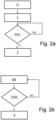
- Fig. 2a shows an example of a representative flow diagram of the method of the present invention:
- step 2 includes the isolation of both hydraulic accumulators.
- the method optionally includes, with reference to Fig. 2b , the new pressurization procedure of the line corresponding to the contracted chamber with the following steps:
- new pressurization is performed by monitoring the excursion of the cylinder rod, in the sense that it is stopped when the minimum appreciable variation in the relative position is detected.
- the present invention can advantageously be carried out by means of a computer program, which includes coding means for carrying out one or more steps of the method, when this program is executed on a computer. It is therefore understood that the scope of protection extends to said computer program and further to computer readable means comprising a recorded message, said computer readable means comprising program coding means for carrying out one or more steps of the method, when said program is run on a computer. Constructive variations to the non-limiting example described are possible, without departing from the scope of protection of the present invention, including all the equivalent embodiments for a person skilled in the art, to the content of the claims.
Landscapes
- Engineering & Computer Science (AREA)
- Mechanical Engineering (AREA)
- Vehicle Body Suspensions (AREA)
Applications Claiming Priority (1)
| Application Number | Priority Date | Filing Date | Title |
|---|---|---|---|
| IT102023000022137A IT202300022137A1 (it) | 2023-10-23 | 2023-10-23 | Metodo di gestione di sospensioni idrauliche per un veicolo agricolo |
Publications (1)
| Publication Number | Publication Date |
|---|---|
| EP4545320A1 true EP4545320A1 (fr) | 2025-04-30 |
Family
ID=89308597
Family Applications (1)
| Application Number | Title | Priority Date | Filing Date |
|---|---|---|---|
| EP24207124.9A Pending EP4545320A1 (fr) | 2023-10-23 | 2024-10-17 | Procédé de gestion de suspensions hydrauliques d'un véhicule agricole |
Country Status (2)
| Country | Link |
|---|---|
| EP (1) | EP4545320A1 (fr) |
| IT (1) | IT202300022137A1 (fr) |
Citations (3)
| Publication number | Priority date | Publication date | Assignee | Title |
|---|---|---|---|---|
| US7530434B2 (en) * | 2004-11-23 | 2009-05-12 | Deere & Company | Hydraulic system |
| CA2528670C (fr) * | 2005-12-02 | 2011-02-01 | Deere & Company | Systeme hydraulique |
| US20180229570A1 (en) * | 2017-02-10 | 2018-08-16 | CNH Industrial America, LLC | Position/Height-Based Hydraulic Suspension System and Methods of Using the Same |
-
2023
- 2023-10-23 IT IT102023000022137A patent/IT202300022137A1/it unknown
-
2024
- 2024-10-17 EP EP24207124.9A patent/EP4545320A1/fr active Pending
Patent Citations (3)
| Publication number | Priority date | Publication date | Assignee | Title |
|---|---|---|---|---|
| US7530434B2 (en) * | 2004-11-23 | 2009-05-12 | Deere & Company | Hydraulic system |
| CA2528670C (fr) * | 2005-12-02 | 2011-02-01 | Deere & Company | Systeme hydraulique |
| US20180229570A1 (en) * | 2017-02-10 | 2018-08-16 | CNH Industrial America, LLC | Position/Height-Based Hydraulic Suspension System and Methods of Using the Same |
Also Published As
| Publication number | Publication date |
|---|---|
| IT202300022137A1 (it) | 2025-04-23 |
Similar Documents
| Publication | Publication Date | Title |
|---|---|---|
| US8465025B2 (en) | Gas spring assembly for a vehicle suspension | |
| EP1056609B1 (fr) | Suspension hydraulique antiroulis, pret a monter et procede relatif a des vehicules de manutention de charges | |
| US8065875B2 (en) | Method for springing a movement of an implement of a work machine | |
| US10029533B1 (en) | Vehicle suspension control system | |
| US6471196B2 (en) | Method for controlling the level of a vehicle body of a motor vehicle | |
| US9091039B2 (en) | Ride control system | |
| JP2003072340A (ja) | オフロード車用2重モード再生サスペンション | |
| JP2006159993A (ja) | 車両懸架システム | |
| EP3483453A1 (fr) | Véhicule de travail électro-hydraulique à récupération d'énergie | |
| CA2666297A1 (fr) | Compensation des fuites electrohydrauliques | |
| US12404878B2 (en) | Actuating device for at least one fluidically drivable consumer | |
| EP4545320A1 (fr) | Procédé de gestion de suspensions hydrauliques d'un véhicule agricole | |
| US11613453B2 (en) | Variable hydraulic pressure relief systems and methods for a material handling vehicle | |
| JP6673205B2 (ja) | 蓄圧器ラック | |
| JP5191359B2 (ja) | 水陸両用車の懸架装置 | |
| US6369339B1 (en) | Apparatus for manipulating a load | |
| DE102014113208A1 (de) | Mobile Arbeitsmaschine, insbesondere Flurförderzeug | |
| CN101443204A (zh) | 具有自动定心致动器的车辆侧倾控制系统 | |
| CN214894053U (zh) | 一种千斤顶测试系统 | |
| EP1733996B1 (fr) | Dispositif hydraulique pour lever et baisser un bras articulé à un véhicule de travail | |
| RU2774481C1 (ru) | Энергосберегающий гидропривод механизма подъема стрелы лесного манипулятора | |
| CN116653532B (zh) | 工程机械及其液压悬挂系统 | |
| EP1772296A1 (fr) | Véhicule | |
| JP5075107B2 (ja) | 作業車のサスペンション構造 | |
| WO2007142570A1 (fr) | Dispositif de ventilation d'un système hydraulique dans un véhicule automobile |
Legal Events
| Date | Code | Title | Description |
|---|---|---|---|
| PUAI | Public reference made under article 153(3) epc to a published international application that has entered the european phase |
Free format text: ORIGINAL CODE: 0009012 |
|
| STAA | Information on the status of an ep patent application or granted ep patent |
Free format text: STATUS: THE APPLICATION HAS BEEN PUBLISHED |
|
| AK | Designated contracting states |
Kind code of ref document: A1 Designated state(s): AL AT BE BG CH CY CZ DE DK EE ES FI FR GB GR HR HU IE IS IT LI LT LU LV MC ME MK MT NL NO PL PT RO RS SE SI SK SM TR |
|
| STAA | Information on the status of an ep patent application or granted ep patent |
Free format text: STATUS: REQUEST FOR EXAMINATION WAS MADE |
|
| 17P | Request for examination filed |
Effective date: 20251030 |
|
| GRAP | Despatch of communication of intention to grant a patent |
Free format text: ORIGINAL CODE: EPIDOSNIGR1 |
|
| STAA | Information on the status of an ep patent application or granted ep patent |
Free format text: STATUS: GRANT OF PATENT IS INTENDED |
|
| RIC1 | Information provided on ipc code assigned before grant |
Ipc: B60G 11/26 20060101AFI20260302BHEP Ipc: B60G 17/056 20060101ALI20260302BHEP Ipc: B60G 17/017 20060101ALI20260302BHEP Ipc: F16F 9/08 20060101ALI20260302BHEP |
|
| INTG | Intention to grant announced |
Effective date: 20260330 |