EP4545348A1 - Réseau de traction pour un véhicule automobile - Google Patents
Réseau de traction pour un véhicule automobile Download PDFInfo
- Publication number
- EP4545348A1 EP4545348A1 EP24194222.6A EP24194222A EP4545348A1 EP 4545348 A1 EP4545348 A1 EP 4545348A1 EP 24194222 A EP24194222 A EP 24194222A EP 4545348 A1 EP4545348 A1 EP 4545348A1
- Authority
- EP
- European Patent Office
- Prior art keywords
- bidfets
- converter
- traction network
- charging
- bridges
- Prior art date
- Legal status (The legal status is an assumption and is not a legal conclusion. Google has not performed a legal analysis and makes no representation as to the accuracy of the status listed.)
- Pending
Links
Images



Classifications
-
- B—PERFORMING OPERATIONS; TRANSPORTING
- B60—VEHICLES IN GENERAL
- B60L—PROPULSION OF ELECTRICALLY-PROPELLED VEHICLES; SUPPLYING ELECTRIC POWER FOR AUXILIARY EQUIPMENT OF ELECTRICALLY-PROPELLED VEHICLES; ELECTRODYNAMIC BRAKE SYSTEMS FOR VEHICLES IN GENERAL; MAGNETIC SUSPENSION OR LEVITATION FOR VEHICLES; MONITORING OPERATING VARIABLES OF ELECTRICALLY-PROPELLED VEHICLES; ELECTRIC SAFETY DEVICES FOR ELECTRICALLY-PROPELLED VEHICLES
- B60L53/00—Methods of charging batteries, specially adapted for electric vehicles; Charging stations or on-board charging equipment therefor; Exchange of energy storage elements in electric vehicles
- B60L53/20—Methods of charging batteries, specially adapted for electric vehicles; Charging stations or on-board charging equipment therefor; Exchange of energy storage elements in electric vehicles characterised by converters located in the vehicle
- B60L53/24—Using the vehicle's propulsion converter for charging
-
- B—PERFORMING OPERATIONS; TRANSPORTING
- B60—VEHICLES IN GENERAL
- B60L—PROPULSION OF ELECTRICALLY-PROPELLED VEHICLES; SUPPLYING ELECTRIC POWER FOR AUXILIARY EQUIPMENT OF ELECTRICALLY-PROPELLED VEHICLES; ELECTRODYNAMIC BRAKE SYSTEMS FOR VEHICLES IN GENERAL; MAGNETIC SUSPENSION OR LEVITATION FOR VEHICLES; MONITORING OPERATING VARIABLES OF ELECTRICALLY-PROPELLED VEHICLES; ELECTRIC SAFETY DEVICES FOR ELECTRICALLY-PROPELLED VEHICLES
- B60L53/00—Methods of charging batteries, specially adapted for electric vehicles; Charging stations or on-board charging equipment therefor; Exchange of energy storage elements in electric vehicles
- B60L53/20—Methods of charging batteries, specially adapted for electric vehicles; Charging stations or on-board charging equipment therefor; Exchange of energy storage elements in electric vehicles characterised by converters located in the vehicle
- B60L53/22—Constructional details or arrangements of charging converters specially adapted for charging electric vehicles
-
- B—PERFORMING OPERATIONS; TRANSPORTING
- B60—VEHICLES IN GENERAL
- B60L—PROPULSION OF ELECTRICALLY-PROPELLED VEHICLES; SUPPLYING ELECTRIC POWER FOR AUXILIARY EQUIPMENT OF ELECTRICALLY-PROPELLED VEHICLES; ELECTRODYNAMIC BRAKE SYSTEMS FOR VEHICLES IN GENERAL; MAGNETIC SUSPENSION OR LEVITATION FOR VEHICLES; MONITORING OPERATING VARIABLES OF ELECTRICALLY-PROPELLED VEHICLES; ELECTRIC SAFETY DEVICES FOR ELECTRICALLY-PROPELLED VEHICLES
- B60L50/00—Electric propulsion with power supplied within the vehicle
- B60L50/50—Electric propulsion with power supplied within the vehicle using propulsion power supplied by batteries or fuel cells
- B60L50/60—Electric propulsion with power supplied within the vehicle using propulsion power supplied by batteries or fuel cells using power supplied by batteries
-
- B—PERFORMING OPERATIONS; TRANSPORTING
- B60—VEHICLES IN GENERAL
- B60L—PROPULSION OF ELECTRICALLY-PROPELLED VEHICLES; SUPPLYING ELECTRIC POWER FOR AUXILIARY EQUIPMENT OF ELECTRICALLY-PROPELLED VEHICLES; ELECTRODYNAMIC BRAKE SYSTEMS FOR VEHICLES IN GENERAL; MAGNETIC SUSPENSION OR LEVITATION FOR VEHICLES; MONITORING OPERATING VARIABLES OF ELECTRICALLY-PROPELLED VEHICLES; ELECTRIC SAFETY DEVICES FOR ELECTRICALLY-PROPELLED VEHICLES
- B60L53/00—Methods of charging batteries, specially adapted for electric vehicles; Charging stations or on-board charging equipment therefor; Exchange of energy storage elements in electric vehicles
- B60L53/10—Methods of charging batteries, specially adapted for electric vehicles; Charging stations or on-board charging equipment therefor; Exchange of energy storage elements in electric vehicles characterised by the energy transfer between the charging station and the vehicle
- B60L53/14—Conductive energy transfer
-
- B—PERFORMING OPERATIONS; TRANSPORTING
- B60—VEHICLES IN GENERAL
- B60L—PROPULSION OF ELECTRICALLY-PROPELLED VEHICLES; SUPPLYING ELECTRIC POWER FOR AUXILIARY EQUIPMENT OF ELECTRICALLY-PROPELLED VEHICLES; ELECTRODYNAMIC BRAKE SYSTEMS FOR VEHICLES IN GENERAL; MAGNETIC SUSPENSION OR LEVITATION FOR VEHICLES; MONITORING OPERATING VARIABLES OF ELECTRICALLY-PROPELLED VEHICLES; ELECTRIC SAFETY DEVICES FOR ELECTRICALLY-PROPELLED VEHICLES
- B60L53/00—Methods of charging batteries, specially adapted for electric vehicles; Charging stations or on-board charging equipment therefor; Exchange of energy storage elements in electric vehicles
- B60L53/20—Methods of charging batteries, specially adapted for electric vehicles; Charging stations or on-board charging equipment therefor; Exchange of energy storage elements in electric vehicles characterised by converters located in the vehicle
-
- H—ELECTRICITY
- H02—GENERATION; CONVERSION OR DISTRIBUTION OF ELECTRIC POWER
- H02J—ELECTRIC POWER NETWORKS; CIRCUIT ARRANGEMENTS OR SYSTEMS FOR SUPPLYING OR DISTRIBUTING ELECTRIC POWER; SYSTEMS FOR STORING ELECTRIC ENERGY
- H02J7/00—Circuit arrangements for charging or discharging batteries or for supplying loads from batteries
- H02J7/02—Circuit arrangements for charging or discharging batteries or for supplying loads from batteries for charging batteries from AC mains by converters
-
- H—ELECTRICITY
- H02—GENERATION; CONVERSION OR DISTRIBUTION OF ELECTRIC POWER
- H02M—APPARATUS FOR CONVERSION BETWEEN AC AND AC, BETWEEN AC AND DC, OR BETWEEN DC AND DC, AND FOR USE WITH MAINS OR SIMILAR POWER SUPPLY SYSTEMS; CONVERSION OF DC OR AC INPUT POWER INTO SURGE OUTPUT POWER; CONTROL OR REGULATION THEREOF
- H02M1/00—Details of apparatus for conversion
- H02M1/0067—Converter structures employing plural converter units, other than for parallel operation of the units on a single load
- H02M1/007—Plural converter units in cascade
-
- H—ELECTRICITY
- H02—GENERATION; CONVERSION OR DISTRIBUTION OF ELECTRIC POWER
- H02M—APPARATUS FOR CONVERSION BETWEEN AC AND AC, BETWEEN AC AND DC, OR BETWEEN DC AND DC, AND FOR USE WITH MAINS OR SIMILAR POWER SUPPLY SYSTEMS; CONVERSION OF DC OR AC INPUT POWER INTO SURGE OUTPUT POWER; CONTROL OR REGULATION THEREOF
- H02M7/00—Conversion of AC power input into DC power output; Conversion of DC power input into AC power output
- H02M7/42—Conversion of DC power input into AC power output without possibility of reversal
- H02M7/44—Conversion of DC power input into AC power output without possibility of reversal by static converters
- H02M7/48—Conversion of DC power input into AC power output without possibility of reversal by static converters using discharge tubes with control electrode or semiconductor devices with control electrode
- H02M7/483—Converters with outputs that each can have more than two voltages levels
- H02M7/487—Neutral point clamped inverters
-
- H—ELECTRICITY
- H02—GENERATION; CONVERSION OR DISTRIBUTION OF ELECTRIC POWER
- H02M—APPARATUS FOR CONVERSION BETWEEN AC AND AC, BETWEEN AC AND DC, OR BETWEEN DC AND DC, AND FOR USE WITH MAINS OR SIMILAR POWER SUPPLY SYSTEMS; CONVERSION OF DC OR AC INPUT POWER INTO SURGE OUTPUT POWER; CONTROL OR REGULATION THEREOF
- H02M7/00—Conversion of AC power input into DC power output; Conversion of DC power input into AC power output
- H02M7/66—Conversion of AC power input into DC power output; Conversion of DC power input into AC power output with possibility of reversal
- H02M7/68—Conversion of AC power input into DC power output; Conversion of DC power input into AC power output with possibility of reversal by static converters
- H02M7/72—Conversion of AC power input into DC power output; Conversion of DC power input into AC power output with possibility of reversal by static converters using discharge tubes with control electrode or semiconductor devices with control electrode
- H02M7/79—Conversion of AC power input into DC power output; Conversion of DC power input into AC power output with possibility of reversal by static converters using discharge tubes with control electrode or semiconductor devices with control electrode using devices of a triode or transistor type requiring continuous application of a control signal
- H02M7/797—Conversion of AC power input into DC power output; Conversion of DC power input into AC power output with possibility of reversal by static converters using discharge tubes with control electrode or semiconductor devices with control electrode using devices of a triode or transistor type requiring continuous application of a control signal using semiconductor devices only
-
- B—PERFORMING OPERATIONS; TRANSPORTING
- B60—VEHICLES IN GENERAL
- B60L—PROPULSION OF ELECTRICALLY-PROPELLED VEHICLES; SUPPLYING ELECTRIC POWER FOR AUXILIARY EQUIPMENT OF ELECTRICALLY-PROPELLED VEHICLES; ELECTRODYNAMIC BRAKE SYSTEMS FOR VEHICLES IN GENERAL; MAGNETIC SUSPENSION OR LEVITATION FOR VEHICLES; MONITORING OPERATING VARIABLES OF ELECTRICALLY-PROPELLED VEHICLES; ELECTRIC SAFETY DEVICES FOR ELECTRICALLY-PROPELLED VEHICLES
- B60L2210/00—Converter types
- B60L2210/10—DC to DC converters
-
- H—ELECTRICITY
- H02—GENERATION; CONVERSION OR DISTRIBUTION OF ELECTRIC POWER
- H02J—ELECTRIC POWER NETWORKS; CIRCUIT ARRANGEMENTS OR SYSTEMS FOR SUPPLYING OR DISTRIBUTING ELECTRIC POWER; SYSTEMS FOR STORING ELECTRIC ENERGY
- H02J2207/00—Details of circuit arrangements for charging or discharging batteries or supplying loads from batteries
- H02J2207/20—Charging or discharging characterised by the power electronics converter
Definitions
- the invention relates to a traction network for a motor vehicle.
- the typical structure of a traction network consists of a traction battery, an inverter, and an electric motor.
- Many different topologies are known for the design of the individual components of such a traction network.
- traction networks are known in which the nominal voltage of the traction battery is 800 V.
- Another problem is the inconsistent charging infrastructure, where both 400 V and 800 V DC charging stations are available.
- the maximum charging power cannot be fully utilized or the circuitry complexity is very high.
- a rectifier is located between the AC charging port and the high-voltage battery, converting the alternating current into direct current.
- a DC/DC converter may also be provided, which adjusts the rectified voltage to the voltage level of the high-voltage battery.
- a Weissach rectifier arrangement is known that can be adapted to various configurations on the AC charging side.
- Another traction network is from the US 10,562,404 B1 known, which is designed to be charged from a single-, two- or three-phase AC voltage source.
- the technical problem is to design the traction networks as compactly as possible and with as few components as possible.
- the invention is based on the technical problem of creating a more compact traction network.
- the traction network for a motor vehicle comprises at least one high-voltage battery, a DC/DC converter, an intermediate circuit capacitor formed from at least two series-connected capacitors and having a neutral point, an inverter, and a three-phase AC charging connection.
- the three AC charging lines are connected to an AC voltage filter.
- the inverter has three half-bridges, each half-bridge being assigned a monolithic BIDFET.
- the high-side transistors of the BIDFETs are each connected to a center tap of their associated half-bridge, and the low-side transistors of the BIDFETs are each connected to the neutral point of the intermediate circuit capacitor.
- the three AC charging lines are connected to the center taps of the half-bridges or can be connected to them.
- the BIDFETs can be integrated into a module housing of the inverter, preferably being arranged on one or more circuit boards of the half-bridges.
- a PFC rectifier can be integrated into the inverter, eliminating the need for a separate rectifier.
- the arrangement within the inverter makes the design very compact, which also facilitates cooling.
- the BIDFETs enable further advantages, which will be described in more detail later. With an appropriate bidirectional design of the integrated rectifier, vehicle-to-grid, vehicle-to-home, and vehicle-to-utility charging can be implemented, allowing the traction network to also be used as a mobile charging station for other motor vehicles.
- the DC/DC converter is designed as a bidirectional boost/buck converter. This allows for maximum flexibility. For example, a different DC charging infrastructure (400 V or 800 V) can be used, and a desired voltage can be set on the inverter for an optimal operating point of the electric motor, even if the voltage of the high-voltage battery has dropped significantly. This allows the high-voltage battery to be constructed from Na/sodium battery cells, which can exhibit greater voltage drops than Li-ion battery cells.
- the DC/DC converter can also be designed as a two-, three-, or multi-phase interleaved DC/DC converter, whereby the DC/DC converter can also be designed as an asymmetrically interleaved DC/DC converter.
- interleaved DC/DC converters the power can be divided, so that lower demands are placed on the individual components, although the number of components increases.
- Another advantage of an asymmetrically interleaved DC/DC converter is that losses in the lower power range can be reduced.
- the DC/DC converter is designed as a step-down converter that converts the higher voltage at the inverter into the lower voltage of the high-voltage battery.
- the step-down converter can also be bidirectional, so that the lower voltage of the high-voltage battery is boosted during driving.
- the DC/DC converter is designed as a unidirectional step-down converter, with at least one bypass line with at least one switching element arranged between the high-voltage battery and the intermediate circuit capacitor. When the switching element(s) are closed, the DC/DC converter is bypassed. This allows components with lower current carrying capacity to be used, since they only have to carry the charging currents, while the larger driving currents are routed via the bypass lines. This saves costs.
- a controller is configured to drive the BIDFETs during driving operation to generate a three-level pulse pattern. This reduces the motor harmonics on the electric motor, thus reducing motor losses.
- the BIDFETs thus serve as a component of the rectifier during charging operation and as a component of the inverter during driving operation.
- the same gate drivers are assigned to the half-bridge transistors and the BIDFETs, with a switching device configured such that the gate drivers are assigned to the BIDFETs in AC charging mode and to the half-bridge transistors in driving mode.
- a unidirectional rectifier is formed by the freewheeling diodes of the transistors and the BIDFETs. This eliminates the need for six gate drivers, but then no longer allows for feedback to the grid or other components, and only a 2-level pulse pattern can be set in driving mode.
- a switching device is provided that is designed to disconnect an electric machine from the AC charging lines during AC charging operation. This allows the electric machine to be de-energized during AC charging operation, so that no undesirable drive torques are generated at the electric machine.
- an AC filter (alternating voltage filter) and an active leakage current filter are arranged between the AC charging connection and the inverter, the latter serving in particular as contact protection.
- the BIDFETs are designed as GaN BIDFETs, which can be operated with very low losses.
- the transistors of the half-bridges are designed as SiC transistors, for example, but can also be designed as GaN transistors.
- the traction network 1 has a high-voltage battery 2, which has, for example, a nominal voltage of 400 V - 420 V.
- the traction network 1 also has an intermediate circuit capacitor C, which is formed from at least two capacitors C1, C2 connected in series and has a neutral point N.
- the traction network 1 also has an inverter 3, at the output of which an electric machine 4 with a gearbox 5 is arranged.
- the traction network 1 also has a three-phase AC charging connection 6, wherein the three charging lines L1-L3 are connected to an AC filter (or AC voltage filter) 7, behind which an active leakage current filter 8 is arranged.
- the outputs of the leakage current filter 8 are then connected to the three AC voltage lines of the inverter 3. It is also shown that voltage measuring devices V are connected in parallel to the capacitors C1, C2 of the intermediate circuit capacitor C.
- An active discharge circuit 9 for the intermediate circuit capacitor C is also shown, consisting of a resistor between HV+ and HV- and a parallel circuit consisting of a further resistor in series with a transistor.
- a current measuring device A is also shown in the HV- line.
- the inverter 3 has three half-bridges H1-H3, with a freewheeling diode D being assigned to each of the transistors T1-T6.
- the transistors T1-T6 are designed, for example, as SiC transistors, with the freewheeling diodes D being able to be designed as intrinsic diodes or as separate, discrete diodes.
- the half-bridges H1-H3 each have a center tap M, with the charging lines L1-L3 being connected to the center taps M. Furthermore, each half-bridge H1-H3 is assigned a monolithic BIDFET 10.
- the BIDFET 10 has a voltage input and a voltage output as well as two control terminals.
- the high-side transistor of the BIDFETs 10 is connected to the respective center tap M of the associated half-bridge H1-H3.
- the low-side transistors of the BIDFETs 10 are connected to the neutral point N of the intermediate circuit capacitor C.
- the BIDFETs 10 are preferably designed as GaN BIDFETs.
- a bidirectional boost/buck converter 12 is arranged as a DC/DC converter 11 between the high-voltage battery 2 and the intermediate circuit capacitor C.
- the 3x indicates that the DC/DC converter 11 is designed as a staggered three-phase interleaved DC/DC converter 11, which can also be asymmetrical, i.e., one phase is designed for lower currents than the other two phases. This allows DC/DC converter 11 to be operated with lower losses at lower power requirements.
- the transistors of DC/DC converter 11 are designed, for example, as SiC transistors (with an intrinsic diode). Two smoothing capacitors are shown at the output of DC/DC converter 11, on the side of the intermediate circuit capacitor C. Finally, a controller 13 is also shown.
- FIG. 7 shows a bidirectional Vienna rectifier 14.
- An inductor is arranged at each of the three AC voltage terminals, each connected to a center tap of a half-bridge. Furthermore, each center tap is connected to a series circuit of two MOSFETs connected in opposite directions. The three series circuits are connected to a common neutral point.
- the controller 13 In AC charging mode, the controller 13 then controls the three half-bridges H1-H3 and the three BIDFETs 10 like a rectifier, and the high-voltage battery 2 is charged via the DC/DC converter 11. Since the rectifier is bidirectional, power from the high-voltage battery 2 can also be fed back into the grid.
- the three half-bridges H1-H3 and the three BIDFETs 10 can then be controlled by the controller 13 in such a way that they generate a 3L pulse pattern.
- the BIDFETs 10 are fully integrated into the inverter 3. For example, if all three half-bridges H1-H3 are arranged on one circuit board, the BIDFETs 10 are preferably also integrated into the circuit board. If there are multiple circuit boards for the half-bridges H1-H3, the BIDFETs 10 are preferably arranged on the circuit board of the associated half-bridge H1-H3. This allows for a very compact design and simplifies cooling.
- the rectifier does not have to be bidirectional, but can be designed as a unidirectional Vienna rectifier 15, as in Fig. 8
- three half-bridges made of diodes are shown.
- the circuitry corresponds to the freewheeling diodes D of the half-bridges H1-H3 of inverter 3, whereby the three series circuits with the oppositely polarized transistors are made of Fig. 8 again corresponds to the BIDFETs 10. Therefore, the transistors T1-T6 are not needed for AC charging.
- FIG. 2 An alternative embodiment for the DC/DC converter 11 is shown as a boost-buck converter 12, wherein the transistors are designed as GaN transistors, which have lower switching losses than SiC transistors.
- FIG. 3 another alternative embodiment is shown which has one less inductance, so that three inductances are saved in a 3-phase interleaved DC/DC converter 11.
- FIG. 4 An alternative traction network 1 is shown, the only difference to the traction network 1 according to Fig. 1 the design of the DC/DC converter 11.
- the DC/DC converter 11 is designed as a bidirectional step-down converter 16, whereby it is assumed that the voltages at the inverter 3 or at the intermediate circuit capacitor are always higher than the voltage of the high-voltage battery 2.
- FIG. 5 another traction network 1 is shown, which is similar to the traction network 1 according to Fig. 4 The only difference is that a bypass line 17 with at least one switching element 18 is arranged between the high-voltage battery 2 and the intermediate circuit capacitor C on both the + side and the - side, whereby the DC/DC converter 11 is bypassed when the switching elements 18 are closed.
- the switching elements 18 are closed during driving and open during AC charging, so that in AC charging the transistors in the DC/DC converter 11 are designed for the lower currents in AC charging.
- the DC/DC converter 11 is then deactivated and bypassed via the bypass lines 17, whereby the switching elements 18 are again controlled via the controller 13. This can save costs.
- one bypass line 17 with switching element 18 is sufficient.
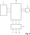
- a switching device 19 is shown, which is controlled by the controller 13.
- the switching device 19 which is controlled by the controller 13
- the AC charging lines L1-L3 are connected to the inverter 3 during AC charging operation, whereby the electric machine 4 is disconnected. In driving operation, however, the AC charging lines L1-L3 are disconnected and the inverter 3 is connected to the electric machine 4.
Landscapes
- Engineering & Computer Science (AREA)
- Power Engineering (AREA)
- Transportation (AREA)
- Mechanical Engineering (AREA)
- Life Sciences & Earth Sciences (AREA)
- Sustainable Development (AREA)
- Sustainable Energy (AREA)
- Dc-Dc Converters (AREA)
Applications Claiming Priority (1)
| Application Number | Priority Date | Filing Date | Title |
|---|---|---|---|
| DE102023210505.5A DE102023210505A1 (de) | 2023-10-25 | 2023-10-25 | Traktionsnetz für ein Kraftfahrzeug |
Publications (1)
| Publication Number | Publication Date |
|---|---|
| EP4545348A1 true EP4545348A1 (fr) | 2025-04-30 |
Family
ID=92409147
Family Applications (1)
| Application Number | Title | Priority Date | Filing Date |
|---|---|---|---|
| EP24194222.6A Pending EP4545348A1 (fr) | 2023-10-25 | 2024-08-13 | Réseau de traction pour un véhicule automobile |
Country Status (3)
| Country | Link |
|---|---|
| EP (1) | EP4545348A1 (fr) |
| CN (1) | CN119872293A (fr) |
| DE (1) | DE102023210505A1 (fr) |
Citations (6)
| Publication number | Priority date | Publication date | Assignee | Title |
|---|---|---|---|---|
| DE102008063465A1 (de) * | 2008-12-17 | 2010-06-24 | Siemens Aktiengesellschaft | Betriebsanordnung für ein elektrisch betriebenes Fahrzeug |
| DE102016206945A1 (de) | 2016-04-25 | 2017-10-26 | Volkswagen Aktiengesellschaft | Kombinierte Multilevel-Umrichter- und ACDC Leistungslade-Einheit |
| DE102018000580A1 (de) * | 2018-01-24 | 2018-07-12 | Daimler Ag | Elektrisches Bordnetz mit einem Inverter und mit einem Gleichspannungswandler, welcher ein Energiespeicherelement in einem Minus-Pfad aufweist |
| US10562404B1 (en) | 2015-10-05 | 2020-02-18 | University Of Maryland | Integrated onboard chargers for plug-in electric vehicles |
| DE102019106485A1 (de) | 2019-03-14 | 2020-09-17 | Dr. Ing. H.C. F. Porsche Aktiengesellschaft | Weissach-Gleichrichteranordnung |
| EP3718201B1 (fr) * | 2017-11-27 | 2022-12-07 | Volkswagen Aktiengesellschaft | Composant redresseur et module semi-conducteur d'un composant redresseur |
Family Cites Families (4)
| Publication number | Priority date | Publication date | Assignee | Title |
|---|---|---|---|---|
| FR3061819B1 (fr) * | 2017-01-12 | 2021-06-18 | Renault Sas | Chargeur de batterie d'accumulateurs electriques bidirectionnel. |
| CN110492580B (zh) * | 2019-09-16 | 2022-04-08 | 阳光电源股份有限公司 | 直流充电系统控制方法、直流充电系统及控制器 |
| CN112532101A (zh) * | 2020-12-17 | 2021-03-19 | 哈尔滨理工大学 | 一种新型双向高变比vienna整流器 |
| DE102021208773B3 (de) * | 2021-08-11 | 2022-08-18 | Volkswagen Aktiengesellschaft | Traktionsnetz für ein Elektrofahrzeug und Verfahren zum Laden |
-
2023
- 2023-10-25 DE DE102023210505.5A patent/DE102023210505A1/de active Pending
-
2024
- 2024-08-13 EP EP24194222.6A patent/EP4545348A1/fr active Pending
- 2024-10-22 CN CN202411472200.7A patent/CN119872293A/zh active Pending
Patent Citations (6)
| Publication number | Priority date | Publication date | Assignee | Title |
|---|---|---|---|---|
| DE102008063465A1 (de) * | 2008-12-17 | 2010-06-24 | Siemens Aktiengesellschaft | Betriebsanordnung für ein elektrisch betriebenes Fahrzeug |
| US10562404B1 (en) | 2015-10-05 | 2020-02-18 | University Of Maryland | Integrated onboard chargers for plug-in electric vehicles |
| DE102016206945A1 (de) | 2016-04-25 | 2017-10-26 | Volkswagen Aktiengesellschaft | Kombinierte Multilevel-Umrichter- und ACDC Leistungslade-Einheit |
| EP3718201B1 (fr) * | 2017-11-27 | 2022-12-07 | Volkswagen Aktiengesellschaft | Composant redresseur et module semi-conducteur d'un composant redresseur |
| DE102018000580A1 (de) * | 2018-01-24 | 2018-07-12 | Daimler Ag | Elektrisches Bordnetz mit einem Inverter und mit einem Gleichspannungswandler, welcher ein Energiespeicherelement in einem Minus-Pfad aufweist |
| DE102019106485A1 (de) | 2019-03-14 | 2020-09-17 | Dr. Ing. H.C. F. Porsche Aktiengesellschaft | Weissach-Gleichrichteranordnung |
Also Published As
| Publication number | Publication date |
|---|---|
| CN119872293A (zh) | 2025-04-25 |
| DE102023210505A1 (de) | 2025-04-30 |
Similar Documents
| Publication | Publication Date | Title |
|---|---|---|
| DE102016218304B3 (de) | Vorrichtung zur Spannungswandlung, Traktionsnetz und Verfahren zum Laden einer Batterie | |
| EP2537239B1 (fr) | Onduleur à découpage à 3 étages avec réseau de délestage | |
| EP2781010B1 (fr) | Dispositif et procédé pour charger une batterie de traction d'un véhicule électrique ou hybride | |
| DE102021208773B3 (de) | Traktionsnetz für ein Elektrofahrzeug und Verfahren zum Laden | |
| DE102018221519B4 (de) | Fahrzeugseitige Ladevorrichtung | |
| EP2996235A1 (fr) | Convertisseur cc/cc | |
| EP2623363B1 (fr) | Dispositif et procédé de chargement d'une batterie de traction d'un véhicule électrique | |
| DE102020200794B4 (de) | Lade- und Heizschaltung | |
| EP2586646B1 (fr) | Dispositif électrique d'alimentation en énergie pour dispositifs d'entraînement destiné au fonctionnement d'un véhicule sur rail sur des réseaux d'alimentation électriques | |
| DE102018207290A1 (de) | Konfigurierbare Ladevorrichtung und Verfahren zum Konfigurieren der Ladevorrichtung | |
| DE102012202764A1 (de) | Ladevorrichtung eines elektrisch betriebenen Fahrzeugs | |
| DE102011079214B4 (de) | Umrichterschaltung mit zwei Umrichtern, die in Abhängigkeit von einem Zustand der Umrichterschaltung zwischen einer Parallelschaltung und einer Seriellschaltung umschaltbar sind | |
| WO2013072107A1 (fr) | Dispositif accumulateur d'énergie, système doté d'un dispositif accumulateur d'énergie et procédé de commande d'un dispositif accumulateur d'énergie | |
| EP2928060A1 (fr) | Circuit de convertisseur modulaire doté de sous-modules présentant différentes capacités de commutation | |
| DE102021205265A1 (de) | Fahrzeug-Spannungswandler und Fahrzeugbordnetz mit einem Spannungswandler | |
| DE4026955C2 (de) | Umrichter | |
| DE102018212523B4 (de) | Fahrzeugseitige Ladeschaltung | |
| DE102017203233A1 (de) | Modularer Wechselrichter | |
| WO2016091300A1 (fr) | Convertisseur continu-continu bidirectionnel à circuit intermédiaire divisé | |
| DE102024201086A1 (de) | Stromrichter und Betriebsverfahren für einen Stromrichter | |
| EP4545348A1 (fr) | Réseau de traction pour un véhicule automobile | |
| EP3513475B1 (fr) | Système servant à transmettre une puissance électrique comprenant une unité de filtrage | |
| EP2608398A1 (fr) | Convertisseur de puissance modulaire | |
| DE102023210787B3 (de) | Traktionsnetz für ein Kraftfahrzeug | |
| DE102018209139A1 (de) | Wechselspannungs-Ladevorrichtung |
Legal Events
| Date | Code | Title | Description |
|---|---|---|---|
| PUAI | Public reference made under article 153(3) epc to a published international application that has entered the european phase |
Free format text: ORIGINAL CODE: 0009012 |
|
| STAA | Information on the status of an ep patent application or granted ep patent |
Free format text: STATUS: THE APPLICATION HAS BEEN PUBLISHED |
|
| AK | Designated contracting states |
Kind code of ref document: A1 Designated state(s): AL AT BE BG CH CY CZ DE DK EE ES FI FR GB GR HR HU IE IS IT LI LT LU LV MC ME MK MT NL NO PL PT RO RS SE SI SK SM TR |
|
| STAA | Information on the status of an ep patent application or granted ep patent |
Free format text: STATUS: REQUEST FOR EXAMINATION WAS MADE |
|
| 17P | Request for examination filed |
Effective date: 20251030 |