EP4545363A1 - Stossfängerandruckvorrichtung für ein kraftfahrzeug mit seitlicher verstärkungsverlängerung - Google Patents
Stossfängerandruckvorrichtung für ein kraftfahrzeug mit seitlicher verstärkungsverlängerung Download PDFInfo
- Publication number
- EP4545363A1 EP4545363A1 EP24202034.5A EP24202034A EP4545363A1 EP 4545363 A1 EP4545363 A1 EP 4545363A1 EP 24202034 A EP24202034 A EP 24202034A EP 4545363 A1 EP4545363 A1 EP 4545363A1
- Authority
- EP
- European Patent Office
- Prior art keywords
- bumper
- presser
- connecting edge
- sliding
- motor vehicle
- Prior art date
- Legal status (The legal status is an assumption and is not a legal conclusion. Google has not performed a legal analysis and makes no representation as to the accuracy of the status listed.)
- Pending
Links
Images

Classifications
-
- B—PERFORMING OPERATIONS; TRANSPORTING
- B60—VEHICLES IN GENERAL
- B60R—VEHICLES, VEHICLE FITTINGS, OR VEHICLE PARTS, NOT OTHERWISE PROVIDED FOR
- B60R19/00—Wheel guards; Radiator guards, e.g. grilles; Obstruction removers; Fittings damping bouncing force in collisions
- B60R19/02—Bumpers, i.e. impact receiving or absorbing members for protecting vehicles or fending off blows from other vehicles or objects
- B60R19/24—Arrangements for mounting bumpers on vehicles
-
- B—PERFORMING OPERATIONS; TRANSPORTING
- B62—LAND VEHICLES FOR TRAVELLING OTHERWISE THAN ON RAILS
- B62D—MOTOR VEHICLES; TRAILERS
- B62D65/00—Designing, manufacturing, e.g. assembling, facilitating disassembly, or structurally modifying motor vehicles or trailers, not otherwise provided for
- B62D65/02—Joining sub-units or components to, or positioning sub-units or components with respect to, body shell or other sub-units or components
- B62D65/024—Positioning of sub-units or components with respect to body shell or other sub-units or components
- B62D65/026—Positioning of sub-units or components with respect to body shell or other sub-units or components by using a jig or the like; Positioning of the jig
-
- B—PERFORMING OPERATIONS; TRANSPORTING
- B62—LAND VEHICLES FOR TRAVELLING OTHERWISE THAN ON RAILS
- B62D—MOTOR VEHICLES; TRAILERS
- B62D65/00—Designing, manufacturing, e.g. assembling, facilitating disassembly, or structurally modifying motor vehicles or trailers, not otherwise provided for
- B62D65/02—Joining sub-units or components to, or positioning sub-units or components with respect to, body shell or other sub-units or components
- B62D65/16—Joining sub-units or components to, or positioning sub-units or components with respect to, body shell or other sub-units or components the sub-units or components being exterior fittings, e.g. bumpers, lights, wipers, exhausts
-
- B—PERFORMING OPERATIONS; TRANSPORTING
- B60—VEHICLES IN GENERAL
- B60R—VEHICLES, VEHICLE FITTINGS, OR VEHICLE PARTS, NOT OTHERWISE PROVIDED FOR
- B60R19/00—Wheel guards; Radiator guards, e.g. grilles; Obstruction removers; Fittings damping bouncing force in collisions
- B60R19/02—Bumpers, i.e. impact receiving or absorbing members for protecting vehicles or fending off blows from other vehicles or objects
- B60R19/18—Bumpers, i.e. impact receiving or absorbing members for protecting vehicles or fending off blows from other vehicles or objects characterised by the cross-section; Means within the bumper to absorb impact
- B60R2019/1886—Bumper fascias and fastening means therefor
-
- B—PERFORMING OPERATIONS; TRANSPORTING
- B60—VEHICLES IN GENERAL
- B60R—VEHICLES, VEHICLE FITTINGS, OR VEHICLE PARTS, NOT OTHERWISE PROVIDED FOR
- B60R19/00—Wheel guards; Radiator guards, e.g. grilles; Obstruction removers; Fittings damping bouncing force in collisions
- B60R19/02—Bumpers, i.e. impact receiving or absorbing members for protecting vehicles or fending off blows from other vehicles or objects
- B60R19/24—Arrangements for mounting bumpers on vehicles
- B60R2019/247—Fastening of bumpers' side ends
Definitions
- the present invention relates to the field of motor vehicles, more particularly the field of motor vehicle bumpers.
- pressers are not without problems that can have an impact on the quality of the final assembly as well as on the safety of the vehicles. Indeed, among these problems we can mention the risk of sagging and/or deformation of the side brackets of the bumper skin attached to the corresponding presser, which often result from the efforts exerted by the assembly technicians during adjustments to the position of the pressers.
- the present invention aims to overcome at least one of the drawbacks of the aforementioned state of the art. More particularly, the invention aims to offer a simple, efficient and economical solution to guarantee good quality assemblies of bumpers on the bodywork of motor vehicles.
- the sliding presser comprises at least one holding clip configured to be engaged by sliding said presser along the inner face of the corresponding connecting edge, until an engagement of said at least one holding clip with a corresponding hole on said connecting edge.
- the lateral portion comprises a lateral rib flush with a rear face of the sliding presser, said lateral rib forming a base from which an extension wall extends vertically and projects.
- the extension wall comprises a bathtub shape extending vertically over a height corresponding substantially to a total thickness of the sliding presser presented between the rear face and a front face of said sliding presser bearing against the inner face of the connecting edge.
- the lateral portion comprises at least one vertical rib extending vertically from the base and connecting the extension wall to a lateral face of the sliding presser.
- the at least one vertical rib comprises three ribs parallel and substantially perpendicular to the lateral face of the sliding presser.
- the side portion comprises a width extending beyond the connecting edge by at least 15 mm along the main direction of the bumper wall.
- the lateral portion extends over a length corresponding to at least one half of a total longitudinal extent of the sliding presser.
- the return portion of the body comprises an L-shaped cross-section matching the lateral portion of the sliding presser.
- the measures of the invention are advantageous in that the lateral portion of the sliding presser corresponds to a lateral extension extending transversely towards the interior of the motor vehicle so as to come to bear on the return portion of the bodywork.
- the supports as well as the thrust and friction forces generated during the sliding of the presser during the assembly of the bumper are advantageously distributed homogeneously over a larger contact surface, shared between the connecting edge and the return portion of the bodywork.
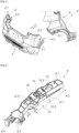
- FIG. 1 represents a perspective view of a bumper 4 according to the invention intended to be manually assembled to a body 6 of a motor vehicle 2, in a longitudinal direction of said motor vehicle represented by the illustrated arrow.
- the bumper comprises a bumper wall 4 having two crossbars 4.1 intended to fit two front or rear corners of the motor vehicle 2.
- the two crossbars 4.1 are here configured to connect to the bodywork 6 at the rear corners of said motor vehicle 2.
- the crosspieces 4.1 end with a connecting edge extending in a main direction of an extent of the bumper wall 4, corresponding to a transverse direction of the motor vehicle 2 in the normal mounting position.
- the sliding presser 8 is arranged to bear against an inner face of the edge of connection, prior to assembly of the assembly with a corresponding side wing 6.1 of the bodywork 6 preferably ending with a return portion of the bodywork.
- FIG. 2 represents a perspective view of the sliding presser 8, the latter is designated by “sliding” because a sliding movement of said presser occurs during the assembly of the bumper to the bodywork, so as to engage at least one pre-holding clip 10, prior to final fixing of the assembly with fixing means by screwing and/or rivets.
- the sliding presser 8 comprises three holding clips 10 configured to be engaged by sliding said presser 8 along the inner face of the corresponding connecting edge (not shown here), with a corresponding hole, arranged in line with the connecting edge and on the return portion of the bodywork.
- each retaining clip 10 is capable of compressing in contact with the connecting edge, so as to be flush with a front face 8.1 of the sliding presser 8.
- the sliding presser 8 comprises a lateral portion 12 extending towards the interior of the vehicle beyond the connecting edge (visible at Figures 3 and 4 ), so that it can rest on the return portion of the bodywork when mounting the bumper on the vehicle.
- the lateral portion 12 of the sliding presser 8 corresponds to a lateral extension extending transversely towards the interior of the motor vehicle.
- the supports, as well as the thrust and friction forces generated by the assembly technician when sliding said presser during assembly of the bumper are advantageously distributed homogeneously over a larger surface area. contact, shared between the connecting edge on the one hand, and the return portion of the bodywork on the other hand.
- the lateral portion 12 comprises a lateral rib 12.1 flush with a rear face 8.2 of the sliding presser 8, said lateral rib 12.1 forming a base 12.1 from which an extension wall 12.2 extends substantially vertically and projects over a height preferably corresponding to a total thickness A of the sliding presser 8 presented between the rear face 8.2 and the front face 8.1.
- the lateral portion 12 further comprises one or more vertical rib(s) 12.3 extending vertically from the base 12.1 and connecting the extension wall 12.2 to a lateral face 8.3 of the sliding presser 8, and more preferably comprises three vertical ribs 12.3 parallel and substantially perpendicular to the lateral face 8.3.
- extension wall 12.2 comprises a bathtub shape with a side opposite the side face 8.3 flush with an edge of the side rib 12.1.
- the lateral portion 12 extends over a length C corresponding to at least half of a total longitudinal extent of the sliding presser 8, and more preferably, over approximately 70% of said total extent.
- the extension wall 12.2 has a length of at least 20% of the total longitudinal extent of the sliding presser 8.
- the vertical ribs 12.3 make it possible to increase the rigidity of the lateral portion 12, which allows it to resist possible counter-forces which may be generated by the support of the extension wall 12.2 against the return portion of the bodywork.
- the base 12.1 comprises a width B extending beyond the connecting edge by at least 15 mm along the main direction of the bumper wall. More preferably, the width B is between 15 mm and 50 mm.
- the width B can also be measured between the side face 8.3 of the presser 8 and a side end of the base 12.1, since the connecting edge stops at the side face 8.3, as illustrated in Figure 3 .
- the retaining clips 10 extend through the corresponding holes 4.3 of the connecting edge 4.2, this is a normal mounting position of the bumper 4 and the sliding presser 8 on the body of the motor vehicle after sliding of said presser 8 by a manual pushing force (illustrated by the dotted arrow) exerted at its lower portion 8.4.
- the return portion of the body is hidden in order to facilitate reading of the Figure 3 .
- the connecting edge 4.2 preferably comprises two centering pins 4.4 making it possible to ensure pre-positioning of the crosspiece 4.1 on the wing of the corresponding bodywork, and this prior to fixing by rivets 14 with the bodywork of the motor vehicle.
- FIG. 4 represents a sectional view along an axis AA passing through the connecting edge 4.2 and the sliding presser 8 of the Figure 3 , as well as the return portion of the 6.2 body.
- the sliding presser 8 is arranged against the inner face 4.5 and the lateral portion 12 laterally exceeds the connecting edge 4.2 to come to bear against the bodywork 6.
- the return portion of the bodywork 6.2 comprises an L-shaped cross-section matching and enveloping the lateral portion 12 of the sliding presser 8.
- the lateral portion 12 represents a reinforced technical zone bearing on the sheet metal at right angles to the return portion 6.2, and this permanently during sliding and after assembly, in order to guarantee that the sliding presser 8 is held in position to prevent the bumper wall 4 from collapsing locally.
Landscapes
- Engineering & Computer Science (AREA)
- Mechanical Engineering (AREA)
- Manufacturing & Machinery (AREA)
- Chemical & Material Sciences (AREA)
- Combustion & Propulsion (AREA)
- Transportation (AREA)
- Body Structure For Vehicles (AREA)
Applications Claiming Priority (1)
| Application Number | Priority Date | Filing Date | Title |
|---|---|---|---|
| FR2311473A FR3154367A1 (fr) | 2023-10-23 | 2023-10-23 | Presseur de pare-chocs de véhicule automobile comprenant une extension latérale de renforcement |
Publications (1)
| Publication Number | Publication Date |
|---|---|
| EP4545363A1 true EP4545363A1 (de) | 2025-04-30 |
Family
ID=89068885
Family Applications (1)
| Application Number | Title | Priority Date | Filing Date |
|---|---|---|---|
| EP24202034.5A Pending EP4545363A1 (de) | 2023-10-23 | 2024-09-23 | Stossfängerandruckvorrichtung für ein kraftfahrzeug mit seitlicher verstärkungsverlängerung |
Country Status (2)
| Country | Link |
|---|---|
| EP (1) | EP4545363A1 (de) |
| FR (1) | FR3154367A1 (de) |
Citations (3)
| Publication number | Priority date | Publication date | Assignee | Title |
|---|---|---|---|---|
| DE19736755A1 (de) * | 1997-08-23 | 1999-02-25 | Volkswagen Ag | Befestigungsanordnung für ein gestrecktes Profilteil an einem Träger, insbesondere für eine seitliche Stoßfängerabdeckung an einem karosserieseitigen Trägerprofil |
| DE102007032929A1 (de) * | 2007-07-14 | 2008-02-21 | Daimler Ag | Befestigungsanordnung zur Fixierung einer Stoßfängerverkleidung |
| FR2921031A1 (fr) * | 2007-09-14 | 2009-03-20 | Peugeot Citroen Automobiles Sa | Element de pare-chocs comprenant une peau de pare-chocs et un presseur, et vehicule automobile comprenant un tel element de pare-chocs |
-
2023
- 2023-10-23 FR FR2311473A patent/FR3154367A1/fr active Pending
-
2024
- 2024-09-23 EP EP24202034.5A patent/EP4545363A1/de active Pending
Patent Citations (3)
| Publication number | Priority date | Publication date | Assignee | Title |
|---|---|---|---|---|
| DE19736755A1 (de) * | 1997-08-23 | 1999-02-25 | Volkswagen Ag | Befestigungsanordnung für ein gestrecktes Profilteil an einem Träger, insbesondere für eine seitliche Stoßfängerabdeckung an einem karosserieseitigen Trägerprofil |
| DE102007032929A1 (de) * | 2007-07-14 | 2008-02-21 | Daimler Ag | Befestigungsanordnung zur Fixierung einer Stoßfängerverkleidung |
| FR2921031A1 (fr) * | 2007-09-14 | 2009-03-20 | Peugeot Citroen Automobiles Sa | Element de pare-chocs comprenant une peau de pare-chocs et un presseur, et vehicule automobile comprenant un tel element de pare-chocs |
Also Published As
| Publication number | Publication date |
|---|---|
| FR3154367A1 (fr) | 2025-04-25 |
Similar Documents
| Publication | Publication Date | Title |
|---|---|---|
| EP0720935B1 (de) | Vorrichtung zur präzisen Positionierung eines Stossfängers zu einem Kotflügelteil eines Fahrzeuges | |
| EP1457390B1 (de) | Sensorbefestigungsträger eines Kraftfahrzeuges | |
| WO2008125764A1 (fr) | Organe de positionnement d'une piece de carrosserie sur un vehicule automobile | |
| EP2062804B1 (de) | Vorrichtung und Verfahren zur Befestigung einer Kotflügeleinheit an der Wagenkastenwand eines Kraftfahrzeugs | |
| EP2655167B1 (de) | Vorrichtung zur verstärkung des flügels eines fahrzeugs auf einer karosserie | |
| EP1101691B1 (de) | Vorder- Viertel- Befestigung auf Querträger | |
| WO2018146416A1 (fr) | Dispositif de maintien en position entrebâillée d'un ouvrant sur un élément fixe d'une caisse d'un véhicule | |
| EP4545363A1 (de) | Stossfängerandruckvorrichtung für ein kraftfahrzeug mit seitlicher verstärkungsverlängerung | |
| FR3038289A1 (fr) | Projecteur avant de vehicule automobile muni d’un boitier comportant un element d’ancrage inferieur | |
| EP0497636B1 (de) | Befestigungseinrichtung einer Stossstange eines Fahrzeuges | |
| FR2975353A1 (fr) | Ensemble comprenant une tablette en tole et un enrouleur de ceinture de securite fixe a cette tablette et vehicule automobile equipe d'un tel ensemble | |
| FR3085883A1 (fr) | Roue de vehicule comportant un insert et insert correspondant | |
| EP1728687B1 (de) | Anordnung zur Montage einer Zierleiste an einem Kraftfahrzeug Karosserieteil | |
| FR2789964A1 (fr) | Dispositif de fixation d'un elargisseur d'aile integre a un pare-chocs | |
| FR2982558A3 (fr) | Logement de rangement pour un pene de ceinture de securite | |
| FR2833910A1 (fr) | Pare-chocs arriere deformable pour vehicule | |
| FR3122637A1 (fr) | Dispositif de guidage pour une fixation dans un véhicule automobile et agencement comprenant un tel dispositif. | |
| EP4375166B1 (de) | Hinterradaufhängung eines kraftfahrzeugs, die an einem winkelträger befestigt ist, der an einer holmgurtauskleidung angeschlossen ist | |
| EP1718100B1 (de) | Lautsprechergitteranordnung | |
| EP1877284B1 (de) | Vorderstangenanordnung für ein kraftfahrzeug | |
| WO2024089332A1 (fr) | Presseur de pare-chocs de véhicule automobile permettant un montage transversal | |
| FR3063126B1 (fr) | Protection pour gaine de conducteur electrique ou de fluide de vehicule automobile | |
| FR3062367B1 (fr) | Traverse de planche de bord et console de support de colonne de direction modulaires | |
| FR3155757A1 (fr) | Traverse d’assise destinée à être fixée sur le plancher d’un véhicule automobile | |
| EP4577444A1 (de) | An einer auskleidungsverlängerung des längsträgers eines kraftfahrzeugs befestigtes heck |
Legal Events
| Date | Code | Title | Description |
|---|---|---|---|
| PUAI | Public reference made under article 153(3) epc to a published international application that has entered the european phase |
Free format text: ORIGINAL CODE: 0009012 |
|
| STAA | Information on the status of an ep patent application or granted ep patent |
Free format text: STATUS: THE APPLICATION HAS BEEN PUBLISHED |
|
| AK | Designated contracting states |
Kind code of ref document: A1 Designated state(s): AL AT BE BG CH CY CZ DE DK EE ES FI FR GB GR HR HU IE IS IT LI LT LU LV MC ME MK MT NL NO PL PT RO RS SE SI SK SM TR |
|
| STAA | Information on the status of an ep patent application or granted ep patent |
Free format text: STATUS: REQUEST FOR EXAMINATION WAS MADE |
|
| 17P | Request for examination filed |
Effective date: 20250916 |
|
| STAA | Information on the status of an ep patent application or granted ep patent |
Free format text: STATUS: EXAMINATION IS IN PROGRESS |
|
| 17Q | First examination report despatched |
Effective date: 20251203 |