EP4545373A1 - Schienenfahrzeug, das ein luftleitsystem an einem longitudinalen ende eines einem anderen wagen gegenüberstehenden autodachs umfasst - Google Patents
Schienenfahrzeug, das ein luftleitsystem an einem longitudinalen ende eines einem anderen wagen gegenüberstehenden autodachs umfasst Download PDFInfo
- Publication number
- EP4545373A1 EP4545373A1 EP23306855.0A EP23306855A EP4545373A1 EP 4545373 A1 EP4545373 A1 EP 4545373A1 EP 23306855 A EP23306855 A EP 23306855A EP 4545373 A1 EP4545373 A1 EP 4545373A1
- Authority
- EP
- European Patent Office
- Prior art keywords
- roof
- car
- vehicle
- flap
- intermediate space
- Prior art date
- Legal status (The legal status is an assumption and is not a legal conclusion. Google has not performed a legal analysis and makes no representation as to the accuracy of the status listed.)
- Pending
Links
Images


Classifications
-
- B—PERFORMING OPERATIONS; TRANSPORTING
- B61—RAILWAYS
- B61D—BODY DETAILS OR KINDS OF RAILWAY VEHICLES
- B61D17/00—Construction details of vehicle bodies
- B61D17/02—Construction details of vehicle bodies reducing air resistance by modifying contour ; Constructional features for fast vehicles sustaining sudden variations of atmospheric pressure, e.g. when crossing in tunnels
Definitions
- the present invention deals with a railway vehicle comprising at least a first car and a second car successive in a longitudinal direction in which the vehicle is intended to move, the first car and the second car longitudinally delimiting an intermediate space between themselves, the first car having a first roof extending along a transverse direction perpendicular to the longitudinal direction, and two lateral walls extending from the first roof downwards along an elevation direction perpendicular to the longitudinal direction and to the transverse direction, the second car having a second roof.
- the intermediate space usually hosts various systems, such as electrical and mechanical connections between the first car and the second car, and possibly a gangway allowing passengers to move from the first car to the second car and vice-versa.
- the intermediate space may be at least partly closed radially with respect to the longitudinal direction, for example using lateral bellows connecting the lateral walls of the first car to the lateral walls of the second car.
- the intermediate space usually remains partly open, at least in its upper part, in order to provide easy access to the above mentioned systems, for example for control and/or maintenance. Therefore, in some existing high-speed trains, the lateral sides of the intermediate spaces between the cars are closed, while their top side remains open.
- the level of noise coming from outside the vehicle into in the gangway or a platform located in a longitudinal extremity of a car is significantly higher than in a passenger compartment, for example 10 dB higher, which may create a nuisance for passengers.
- An aim of the invention is to provide a vehicle that reduces the level of noise in the platform and the gangway, if any.
- the invention proposes a railway vehicle comprising at least a first car and a second car successive in a longitudinal direction in which the vehicle is intended to move, the first car and the second car longitudinally delimiting an intermediate space between themselves, the first car having a first roof extending along a transverse direction perpendicular to the longitudinal direction, and two lateral walls extending from the first roof downwards along an elevation direction perpendicular to the longitudinal direction and to the transverse direction, the second car having a second roof, wherein the vehicle further comprises at least a first system fixed to a longitudinal extremity of the first roof facing the second car, the first system having an upper surface in the elevation direction, the upper surface being inclined with respect to the first roof, the first system being adapted for deflecting, away from the intermediate space, a first flow of air flowing longitudinally along the first roof towards the second car, the intermediate space being open in the elevation direction, downstream of the first system with respect to the first flow of air.
- the vehicle comprises one or several of the following features, taken in isolation or any technically feasible combination:
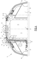
- a railway vehicle 10 according to the invention will now be described with reference to Figures 1 and 2 .
- the vehicle 10 is for example a high-speed train, advantageously designed to travel at a speed greater than 250 km/h under regular commercial operating conditions.
- the vehicle 10 comprises a first car 12 and a second car 14 (partially shown in Figures 1 and 2 ). Only extremities of the car body structures are shown successive in a longitudinal direction L in which the vehicle is intended to move, the first car 12 and the second car 14 longitudinally delimiting an intermediate space 16 between themselves.
- the vehicle 10 may comprise other cars (not shown), in the form of one or several trains (not shown) of cars, each train including two or more cars.
- a transverse direction T of the vehicle 10 is defined as perpendicular to the longitudinal direction L and intended to be horizontal when the vehicle moves on a horizontal surface (not shown).
- An elevation direction V of the vehicle 10 is also defined as perpendicular to the longitudinal direction L and to the transverse direction T. The elevation direction V is thus vertical when the vehicle 10 moves on said horizontal surface.
- the vehicle 10 comprises at least a first system 18 ( Figures 1 to 4 ) adapted for reducing noise coming from the intermediate space 16.
- the vehicle 10 comprises a second system 20 ( Figures 1 and 2 ) and a third system 22 ( Figures 1 to 4 ) having the same purpose.
- the vehicle 10 transversely defines a central zone 24, and two lateral zones 26, 28 ( Figures 2 and 4 ) on either sides of the central zone and symmetrical with respect to a median plane P of the first car 12 perpendicular to the transverse direction T.
- the first system 18 and the second system 20 are within the central zone 24, the third system 22 being in at least one of the two lateral zones 26, 28.
- the vehicle 10 comprises one or several additional system(s) analogous to the first system 18.
- the additional systems are located near the first system 18 in the transverse direction T, and/or near a location that is symmetrical to the location of the first system 18 with respect to the median plane P.
- the vehicle 10 comprises a high voltage cable 30 ( Figures 1 to 4 ) extending longitudinally on a first roof 32 of the first car 12, and a support 34 of the high voltage cable protruding from the first roof in the elevation direction V and in which the high voltage cable is intended to slide.
- high voltage it is for example meant “more than 1000 V”.
- the vehicle 10 comprises a bundle 36 of low voltage cables 38 ( Figures 1 to 4 ), the bundle having a part 40 extending longitudinally on the first roof 32, and another part 42 turning from the first roof into the intermediate space 16.
- low voltage it is for example meant "1000 V or less than 1000 V”.
- the vehicle 10 comprises a gangway 44 adapted for allowing passengers (not shown) to move from the first car 12 to the second car 14 and vice-versa, said gangway crossing the intermediate space 16.
- the first car 12 Apart from the first roof 32, the first car 12 comprises two lateral walls 46, 48 extending from the first roof 32 downwards along the elevation direction V.
- the first roof 32 extends in the transverse direction T, and usually mainly in the longitudinal direction L.
- the first roof 32 is curved and barely has a horizontal portion 50.
- first roof 32 and the lateral walls 46, 48 are continuous in shape around the longitudinal direction L.
- the lateral walls are vertical or inclined for example less than 45° with respect to the elevation direction V, whereas the first roof is inclined for example more than 45° with respect to the elevation direction V.
- the second car 14 is for example analogous to the second car 12 and will not be described in detail.
- the second car 14 comprises a second roof 52, and lateral walls 54, 56.
- the intermediate space 16 is delimited in the longitudinal direction L by a first longitudinal extremity 58 of the first car 12 and a second longitudinal extremity 60 of the second car 14 facing each other.
- the intermediate space 16 is delimited by the gangway 44 radially with respect to the longitudinal direction L, the gangway advantageously having a tubular shape and the intermediate space partly surrounding the gangway.
- the intermediate space 16 is delimited in the elevation direction V downwards by lower parts 62 ( Figures 1 and 2 ) of the first car 12 and the second car 14 adapted for connecting the first car and the second car to each other.
- the intermediate space 16 is at least party closed transversely by flaps (not shown) or similar elements (such as bellows), for example removable, and fixed to the lateral walls 46, 48, 54, 56 of the first car 12 and the second car 14, in order to insure longitudinal continuity of the lateral walls, while allowing access to the intermediate space when the flaps or said similar elements are removed.
- flaps not shown
- similar elements such as bellows
- the first system 18 is fixed to a longitudinal extremity 64 of the first roof 32 facing the second car 14.
- the first system 18 has an upper surface 66 in the elevation direction V, the upper surface being inclined with respect to the first roof 32.
- the first system 18 is transversely delimited by two walls 68, 70 which are advantageously parallel to the longitudinal direction L ( Figure 4 ).
- the first system 18 is offset longitudinally towards the second car 14 relative to the first roof 32. As a variant, not shown, the first system 18 is located on the first roof 32.
- the first system 18 is adapted for deflecting, away from the intermediate space 16 and upwards, a first flow of air 72 ( Figure 3 ) flowing longitudinally along the first roof 32 towards the second car 14, the intermediate space 16 being open in the elevation direction V, downstream of the first system 18 with respect to the first flow of air 72.
- the first system 18 comprises a first portion 74 mounted on the first roof 32 and forming a longitudinal extension of the first roof, and a second portion 76 mounted on top the first portion and defining the upper surface 66 ( Figures 3 and 4 ).
- the first system 18 comprises at least 90wt% of steel.
- the first system 18 is for example located in a transverse extremity 78 of the central zone 24, the transverse extremity 78 being on the side of a first flap 80 of the third system 22 with respect to the median plane P.
- the first system 18 and a portion 82 of the support 34 are located at the same distance D and on either sides of the median plane P ( Figures 2 and 4 ). Thanks to this feature, the first car 12, in the example, does not need a system analogous to the first system 18 and symmetrical to the first system 18 with respect to the median plane P.
- the portion 82 of the support 34 is advantageously adapted for playing the same role as the first system 18, at least to some extent, i.e. deflecting a flow of air (not shown) flowing longitudinally along the first roof 32 towards the second car 14.
- the first system 18 and the other part 42 of the bundle 36 are in mechanical contact or separated by a transverse distance D1 smaller than 25 cm. This allows minimizing the opening of the intermediate space 16 near the first system 18.
- the first system 18 and the first roof 32 have uppermost parts 84, 86 in the elevation direction V defining a distance D2 between them in the elevation direction V, said distance being smaller than 5 cm. This allows not increasing, or not significantly, the height of the first car 12.
- the first car 12 (and the vehicle 10) can have a certain height or gauge, and positioning the first system 18 in the central zone allows not to exceed an authorized height or gauge. On the contrary, positioning the first system 18 in one of the lateral zones 26, 28 could raise an issue in terms of height of the vehicle.
- the first system 18 is spaced apart from the gangway 44 in the transverse direction T, for acoustic reasons and for allowing the other part 42 of the bundle 36 to easily extend between the gangway and the first system.
- the upper surface 66 and the first roof 32 locally define an angle ⁇ comprised between 25° and 30° in order to maximize noise reduction.
- the upper surface 66 is flat.
- the second system 20 is for example structurally analogous to the first system 18 and will not be described in detail.
- the second system 20 is symmetrical to the first system 18 with respect a plane P' perpendicular to the longitudinal direction L and crossing the intermediate space 16.
- the second system 20 is aligned with the first system 18 in the longitudinal direction L.
- the second system 20 is located on the other side of the median plane P with respect to its location in the example, i.e. aligned with the support 34.
- the second system 20 is fixed to a longitudinal extremity 85 of the second roof 52 facing the first car 12.
- the second system 20 is adapted for deflecting, away from the intermediate space 16 and upwards, a second flow of air 87 flowing longitudinally along the second roof 52 towards the first car 12, the intermediate space 16 being open in the elevation direction V, downstream of the second system with respect to the second flow of air.
- the third system 22 includes the first flap 80 and a second flap 88 respectively mounted on the first roof 32 and the second roof 52 in one of the two lateral zones 26, 28, and forming longitudinal extensions of the first roof 32 and the second roof 52 above the intermediate space 16.
- the third system 22 includes a third flap 90 and a fourth flap 92 respectively mounted on the first roof 32 and the second roof 52 in the other of the two lateral zones 26, 28, and forming longitudinal extensions of the first roof 32 and the second roof 52 above the intermediate space 16.
- the first flap 80 and the second flap 88 face each other in the longitudinal direction L in order to partly close the intermediate space 16 along the elevation direction V.
- the first flap 80 comprises a distal portion 94 ( Figure 3 ) with respect to the first roof 32 and the second flap 88 comprises a distal portion 96 with respect to the second roof 52.
- flaps 80, 88, 90, 92 are longitudinal extensions of the first roof 32 and the second roof 52, they advantageously do not form vertical protrusions in the lateral zones 26, 28 with respect to the first roof and the second roof.
- the distal portions 94, 96 for example comprise, or are made of, an elastomeric material.
- the distal portions 94, 96 are advantageously separated by a longitudinal distance D3 when the vehicle moves along a straight line, the longitudinal distance D3 being smaller than 15 cm.
- the third flap 90 and the fourth flap 92 face each other in the longitudinal direction L and partly closing the intermediate space 16 along the elevation direction V.
- the third flap 90 and the fourth flap 92 are advantageously structurally analogous to the first flap 80 and the second flap 88, except that they are shorter in the transverse direction T in the example.
- the first flap 80 comprises a proximal portion 98 with respect to the first roof 32.
- the proximal portion 98 and the first portion 74 of the first system 18 are integral with each other.
- the upper surface 66 of first system 18 deflects the first flow of air 72. It has been noticed that this allows reducing the noise generated within the intermediate space.
- the second system 20 plays the same role by deflecting the second flow of air 87, or the first flow of air 72 depending on whether the vehicle 10 moves to the right or to the left in Figure 2 .
- the third system 22 also reduces interaction between flows of air due to movement of the vehicle 10 and air within the intermediate space 16 in the lateral zones 26, 28.
- the vehicle 10 reduces the level of noise originating from the intermediate space 16 and perceived by the passengers in the gangway 44 or nearby platforms of the first car 12 and the second car 14.
Landscapes
- Engineering & Computer Science (AREA)
- Mechanical Engineering (AREA)
- Fittings On The Vehicle Exterior For Carrying Loads, And Devices For Holding Or Mounting Articles (AREA)
Priority Applications (1)
| Application Number | Priority Date | Filing Date | Title |
|---|---|---|---|
| EP23306855.0A EP4545373A1 (de) | 2023-10-23 | 2023-10-23 | Schienenfahrzeug, das ein luftleitsystem an einem longitudinalen ende eines einem anderen wagen gegenüberstehenden autodachs umfasst |
Applications Claiming Priority (1)
| Application Number | Priority Date | Filing Date | Title |
|---|---|---|---|
| EP23306855.0A EP4545373A1 (de) | 2023-10-23 | 2023-10-23 | Schienenfahrzeug, das ein luftleitsystem an einem longitudinalen ende eines einem anderen wagen gegenüberstehenden autodachs umfasst |
Publications (1)
| Publication Number | Publication Date |
|---|---|
| EP4545373A1 true EP4545373A1 (de) | 2025-04-30 |
Family
ID=88697448
Family Applications (1)
| Application Number | Title | Priority Date | Filing Date |
|---|---|---|---|
| EP23306855.0A Pending EP4545373A1 (de) | 2023-10-23 | 2023-10-23 | Schienenfahrzeug, das ein luftleitsystem an einem longitudinalen ende eines einem anderen wagen gegenüberstehenden autodachs umfasst |
Country Status (1)
| Country | Link |
|---|---|
| EP (1) | EP4545373A1 (de) |
Citations (4)
| Publication number | Priority date | Publication date | Assignee | Title |
|---|---|---|---|---|
| KR101234563B1 (ko) * | 2012-11-01 | 2013-02-19 | 주식회사 한국에스제이 | 전동차량의 공력소음 감소를 위한 머드플랩 |
| FR3092061A1 (fr) * | 2019-01-29 | 2020-07-31 | Sncf Mobilités | Système de déflection d’air et voiture d’extrémité d’un véhicule comprenant un tel système de déflection d’air |
| US20200353957A1 (en) * | 2019-05-08 | 2020-11-12 | Deflect LLC | Deflector for vehicle |
| US10981583B2 (en) * | 2017-06-21 | 2021-04-20 | HÜBNER GmbH & Co. KG | Wind directional system for arrangement between two vehicle parts of a rail vehicle |
-
2023
- 2023-10-23 EP EP23306855.0A patent/EP4545373A1/de active Pending
Patent Citations (4)
| Publication number | Priority date | Publication date | Assignee | Title |
|---|---|---|---|---|
| KR101234563B1 (ko) * | 2012-11-01 | 2013-02-19 | 주식회사 한국에스제이 | 전동차량의 공력소음 감소를 위한 머드플랩 |
| US10981583B2 (en) * | 2017-06-21 | 2021-04-20 | HÜBNER GmbH & Co. KG | Wind directional system for arrangement between two vehicle parts of a rail vehicle |
| FR3092061A1 (fr) * | 2019-01-29 | 2020-07-31 | Sncf Mobilités | Système de déflection d’air et voiture d’extrémité d’un véhicule comprenant un tel système de déflection d’air |
| US20200353957A1 (en) * | 2019-05-08 | 2020-11-12 | Deflect LLC | Deflector for vehicle |
Similar Documents
| Publication | Publication Date | Title |
|---|---|---|
| CA2913841C (en) | Rail vehicle having a concealed undercarriage | |
| EP3086991B1 (de) | Lagerbügel, anordnung mit einem solchen lagerbügel und system mit einer solchen anordnung | |
| DK2383161T4 (en) | Vessel front with reduced lateral wind sensitivity | |
| US20130239844A1 (en) | Vehicle Component Having a Recess with air flowing over it | |
| EP4019363A1 (de) | Gesteuerte dachentwässerung über den faltenbalg | |
| EP4545373A1 (de) | Schienenfahrzeug, das ein luftleitsystem an einem longitudinalen ende eines einem anderen wagen gegenüberstehenden autodachs umfasst | |
| US20050011399A1 (en) | Automated people mover (APM) monorail system | |
| EP3010774B1 (de) | Hochgeschwindigkeitsschienenfahrzeug mit verschlankter nase | |
| JP2010116075A (ja) | 併結編成車両 | |
| US20120234201A1 (en) | Running Gear Frame for a Running Gear of a Rail Vehicle | |
| JP3583497B2 (ja) | 空気流路に存在する空洞の空気力学抵抗を減少させる装置とその装置を有する車両、特に鉄道車両 | |
| JP6722533B2 (ja) | 鉄道車両の車体構造 | |
| AU2014230756B2 (en) | Modular rail vehicle having modules of different widths | |
| KR101306273B1 (ko) | 철도차량용 공기저항 저감장치 | |
| JP7389325B2 (ja) | 鉄道車両及び列車 | |
| KR20220069550A (ko) | 철도 차량의 안티-아이싱 장치 | |
| JP6865004B2 (ja) | 熱交換器システム | |
| US20120216703A1 (en) | Overlong Coach Body for Railway Vehicles and Train Set Composed of Such Coach Bodies | |
| JP6734754B2 (ja) | 鉄道車両 | |
| US20260042472A1 (en) | Vehicle having a cross-sectionally reduced portion | |
| JP7818590B2 (ja) | 車両接続部 | |
| SU1052439A1 (ru) | Транспортное средство | |
| WO2013161017A1 (ja) | パンタグラフ装置 | |
| WO2020105021A2 (en) | The pavan-putra train | |
| JP2006182059A (ja) | 整流カバー |
Legal Events
| Date | Code | Title | Description |
|---|---|---|---|
| PUAI | Public reference made under article 153(3) epc to a published international application that has entered the european phase |
Free format text: ORIGINAL CODE: 0009012 |
|
| STAA | Information on the status of an ep patent application or granted ep patent |
Free format text: STATUS: THE APPLICATION HAS BEEN PUBLISHED |
|
| AK | Designated contracting states |
Kind code of ref document: A1 Designated state(s): AL AT BE BG CH CY CZ DE DK EE ES FI FR GB GR HR HU IE IS IT LI LT LU LV MC ME MK MT NL NO PL PT RO RS SE SI SK SM TR |
|
| STAA | Information on the status of an ep patent application or granted ep patent |
Free format text: STATUS: REQUEST FOR EXAMINATION WAS MADE |
|
| 17P | Request for examination filed |
Effective date: 20251029 |