EP4545381A1 - Verfahren und systeme zur fernunterstützung beim einparken oder ausparken eines fahrzeugs - Google Patents
Verfahren und systeme zur fernunterstützung beim einparken oder ausparken eines fahrzeugs Download PDFInfo
- Publication number
- EP4545381A1 EP4545381A1 EP23205897.4A EP23205897A EP4545381A1 EP 4545381 A1 EP4545381 A1 EP 4545381A1 EP 23205897 A EP23205897 A EP 23205897A EP 4545381 A1 EP4545381 A1 EP 4545381A1
- Authority
- EP
- European Patent Office
- Prior art keywords
- remote device
- vehicle
- data
- challenge response
- valid
- Prior art date
- Legal status (The legal status is an assumption and is not a legal conclusion. Google has not performed a legal analysis and makes no representation as to the accuracy of the status listed.)
- Pending
Links
Images


Classifications
-
- B—PERFORMING OPERATIONS; TRANSPORTING
- B62—LAND VEHICLES FOR TRAVELLING OTHERWISE THAN ON RAILS
- B62D—MOTOR VEHICLES; TRAILERS
- B62D15/00—Steering not otherwise provided for
- B62D15/02—Steering position indicators ; Steering position determination; Steering aids
- B62D15/027—Parking aids, e.g. instruction means
- B62D15/0285—Parking performed automatically
-
- G—PHYSICS
- G05—CONTROLLING; REGULATING
- G05D—SYSTEMS FOR CONTROLLING OR REGULATING NON-ELECTRIC VARIABLES
- G05D1/00—Control of position, course, altitude or attitude of land, water, air or space vehicles, e.g. using automatic pilots
- G05D1/20—Control system inputs
- G05D1/22—Command input arrangements
- G05D1/221—Remote-control arrangements
- G05D1/222—Remote-control arrangements operated by humans
- G05D1/223—Command input arrangements on the remote controller, e.g. joysticks or touch screens
- G05D1/2232—Touch screens
-
- G—PHYSICS
- G08—SIGNALLING
- G08G—TRAFFIC CONTROL SYSTEMS
- G08G1/00—Traffic control systems for road vehicles
- G08G1/14—Traffic control systems for road vehicles indicating individual free spaces in parking areas
- G08G1/141—Traffic control systems for road vehicles indicating individual free spaces in parking areas with means giving the indication of available parking spaces
- G08G1/144—Traffic control systems for road vehicles indicating individual free spaces in parking areas with means giving the indication of available parking spaces on portable or mobile units, e.g. personal digital assistant [PDA]
-
- B—PERFORMING OPERATIONS; TRANSPORTING
- B62—LAND VEHICLES FOR TRAVELLING OTHERWISE THAN ON RAILS
- B62D—MOTOR VEHICLES; TRAILERS
- B62D1/00—Steering controls, i.e. means for initiating a change of direction of the vehicle
-
- G—PHYSICS
- G06—COMPUTING OR CALCULATING; COUNTING
- G06F—ELECTRIC DIGITAL DATA PROCESSING
- G06F3/00—Input arrangements for transferring data to be processed into a form capable of being handled by the computer; Output arrangements for transferring data from processing unit to output unit, e.g. interface arrangements
- G06F3/01—Input arrangements or combined input and output arrangements for interaction between user and computer
- G06F3/048—Interaction techniques based on graphical user interfaces [GUI]
- G06F3/0484—Interaction techniques based on graphical user interfaces [GUI] for the control of specific functions or operations, e.g. selecting or manipulating an object, an image or a displayed text element, setting a parameter value or selecting a range
- G06F3/0486—Drag-and-drop
-
- G—PHYSICS
- G06—COMPUTING OR CALCULATING; COUNTING
- G06F—ELECTRIC DIGITAL DATA PROCESSING
- G06F3/00—Input arrangements for transferring data to be processed into a form capable of being handled by the computer; Output arrangements for transferring data from processing unit to output unit, e.g. interface arrangements
- G06F3/01—Input arrangements or combined input and output arrangements for interaction between user and computer
- G06F3/048—Interaction techniques based on graphical user interfaces [GUI]
- G06F3/0487—Interaction techniques based on graphical user interfaces [GUI] using specific features provided by the input device, e.g. functions controlled by the rotation of a mouse with dual sensing arrangements, or of the nature of the input device, e.g. tap gestures based on pressure sensed by a digitiser
- G06F3/0488—Interaction techniques based on graphical user interfaces [GUI] using specific features provided by the input device, e.g. functions controlled by the rotation of a mouse with dual sensing arrangements, or of the nature of the input device, e.g. tap gestures based on pressure sensed by a digitiser using a touch-screen or digitiser, e.g. input of commands through traced gestures
-
- G—PHYSICS
- G08—SIGNALLING
- G08G—TRAFFIC CONTROL SYSTEMS
- G08G1/00—Traffic control systems for road vehicles
- G08G1/14—Traffic control systems for road vehicles indicating individual free spaces in parking areas
- G08G1/145—Traffic control systems for road vehicles indicating individual free spaces in parking areas where the indication depends on the parking areas
- G08G1/148—Management of a network of parking areas
-
- G—PHYSICS
- G05—CONTROLLING; REGULATING
- G05D—SYSTEMS FOR CONTROLLING OR REGULATING NON-ELECTRIC VARIABLES
- G05D2109/00—Types of controlled vehicles
- G05D2109/10—Land vehicles
Definitions
- the current disclosure relates to a method for a vehicle system to assist to remotely parking or unparking a vehicle.
- the disclosure also relates to a remote device and a vehicle system to assist to remotely parking or unparking a vehicle.
- Newer vehicles have sensors attached providing a 360 degree view of the area surrounding the vehicle.
- the processed information from these sensors can be used to localize nearby objects such as parked cars or vulnerable road users such as humans walking in parking lots.
- This, together with the possibility to connect a remote device to the vehicle and securely locate the remote device in reference to the vehicle enables a user to remotely park the vehicle. This may be useful, for instance, when access to the driver's door is not possible or obstructed.
- Dead man's switch (DMS) solutions can be used to remotely control a vehicle. They are usually implemented as a challenge-response sequence in which the vehicle sends challenges with an identification to a remote device and the remote device should provide a response to the challenge via a phone application depending on the user actions, within a predetermined time.
- the DMS will give enable that the vehicle can give propulsion when engaged and immediately brake once released.
- the challenge should be complicated enough to avoid unintentional responses.
- the challenge should be simple enough to allow the user to focus on the movement of the vehicle while providing the response.
- a known DMS solution for this problem consists of a button provided in an area of a touch screen of the remote device that the driver needs to push and hold in order to give propulsion to the vehicle.
- the vehicle immediately brakes when the button is released, the user is pushing outside the button area, or the distance between the remote device and the vehicle is outside of the designated operation distance.
- the vehicle would in this case accept any response containing x- and y-coordinates that are inside the button displayed on the screen. Once the remote device responds with no coordinates (not pressed) or coordinates outside the area of the button, the vehicle will brake.
- this solution is prompted to failure in some situations. For instance, users tend to freeze in a dangerous situation and may hold the finger on the screen instead of releasing it.
- the methods and systems of the current disclosure allow a user located outside a vehicle but within an activation distance to move the vehicle in any direction by using a remote device (such as a phone or any other mobile device) that interacts with a vehicle system in the vehicle using a Dead Man's Switch (DMS) functionality.
- a remote device such as a phone or any other mobile device
- DMS Dead Man's Switch
- the remote device will respond to a unique challenge from the vehicle system and the vehicle system will validate the response if the response complies with what the vehicle system anticipates.
- the vehicle system will control the vehicle to brake if the interaction is interrupted or the response is not validated.
- This is known as a challenge-response authentication wherein, in an initialization step, a random code may be sent out from the vehicle system together with the coordinates to lay out the user interface in the touch screen of the remote device.
- the remote device will output in the touch screen what the vehicle system requests without having knowledge of the purpose of the request and a user will just follow the instructions on the screen, perform certain inputs on the remote device, and send touch screen positions or other information about the performed inputs.
- the vehicle system will validate the received information.
- the present disclosure relates to a method for a vehicle system to assist to remotely parking or unparking a vehicle, the method comprising transmitting, to a remote device, first data for triggering a challenge response, receiving, as a challenge response from the remote device, second data, wherein the second data comprises information about a touch position on a touch screen of the remote device, determining whether the challenge response is valid, if the challenge response is valid, controlling the vehicle to move, and if the challenge response is not valid, controlling the vehicle to brake, wherein the challenge response is valid if the touch position is different than a previous touch position corresponding to a previously received second data, and if the touch position is within a first threshold distance from the previous touch position.
- the present disclosure relates to a method for a vehicle system to assist to remotely parking or unparking a vehicle, the method comprising transmitting, to a remote device, first data for triggering a challenge response, receiving, as the challenge response from the remote device, second data wherein the second data comprises information about a touch position on a touch screen of the remote device, determining whether the challenge response is valid, if the challenge response is valid, controlling the vehicle to move; and if the challenge response is not valid, controlling the vehicle to brake, wherein the challenge response is valid if the touch position corresponds to an expected swipe movement, wherein the expected swipe movement comprises pressing down on a first zone among a plurality of contiguous zones, continuously moving a finger into subsequent zones and continuously moving the finger back after reaching a final zone among the contiguous zones.
- a continuous movement of the finger in one direction and back through a plurality of contiguous zones is simple enough to allow a user to pay attention to the surroundings but will cause that in a dangerous situation, even if the user freezes, the vehicle will stop.
- the plurality of contiguous zones is not something that is shown on the touch screen of the remote device but it is an agreement between the remote device and the vehicle system to allow the vehicle system to validate the challenge responses from the remote device.
- the remote device and the vehicle system may interchange information to agree a coordinate system for the touch inputs and the position of the valid area. Then the vehicle system can check whether the swipe movement is correctly performed by the user by considering a part of the touch screen divided in contiguous zones and verifying that the swipe input moves through the zones in certain way.
- the expected swipe movement may be called a first swipe movement.
- the expected swipe movement may further comprise continuously moving a finger from one contiguous zone to the next within an expected amount of time that is less than a first time threshold and more than a second time threshold.
- the expected swipe movement may further comprise skipping one or two zones. For instance, the user may sometimes change direction before reaching the final zone, thereby skipping one or two zones.
- the present disclosure relates to a method for a vehicle system to assist to remotely parking or unparking a vehicle, the method comprising transmitting, to a remote device, first data for triggering a challenge response, receiving, as the challenge response, from the remote device, second data, wherein the second data comprises a first information about a touch position on a touch screen of the remote device and a second information indicating a position of the remote device in relation to ground, determining whether the challenge response is valid, if the challenge response is valid, controlling the vehicle to move; and if the challenge response is not valid, controlling the vehicle to brake, wherein the challenge response is valid if the touch position is within a certain range from a previous touch position corresponding to a previously received second data, if the second information indicates that the position of the remote device is different than a previous position indicated by previously received second information, and if the second information range indicates that the remote device forms an angle with the ground within a tilt range.
- the second information indicating the position of the remote device with respect to the ground which may be provided by a gravity sensor of the remote device, will fluctuate even when the user is not actively doing a tilting movement. The fluctuations are used such that the second information sent as a challenge response is not the same as the previous one. In this way, the second information is used by the vehicle system to verify that each challenge response is new.
- the vehicle will brake if the finger is removed from the touch screen or if the remote device is outside the tilt range. In this way, if an error appears and the vehicle does not brake when the finger is removed, the user can still brake by moving the remote device outside of the tilt range.
- the tilt range may be between zero degrees and 90 degrees. However, the tilt range may be any other suitable one.
- the touch position may comprise data of horizontal and vertical coordinates wherein the user input has been received in the touch screen. This is an efficient way of identifying the touch positions and allows remote device and vehicle system to easily agree on the valid area. This coordinate system agreed between vehicle system and remote device allows that the vehicle system can request the remote device to output specific instructions on the touch screen such that the remote device can execute without having any knowledge about the purpose of the request.
- this concept can be used to verify whetherthe user intention is to actually use the parking system. This can be verified by, for instance, requesting the user to push a number of buttons in the right order by touching the expected coordinates on the touch screen. This verification of the user intention does not have to be performed in the vicinity of the car but can also be performed from a distance.
- the vertical and horizontal coordinates may comprise respectively a percentage of a width and height of the touch screen.
- the step of controlling the vehicle to move may comprise controlling the vehicle to move in any direction such as backwards, forwards, right or left.
- the method may further comprise controlling the vehicle to brake if the remote device is not within a certain distance from the vehicle. This ensures that the user can see the vehicle when in movement.
- the method may also comprise controlling the vehicle to brake if the challenge response is not received within a certain time from the transmission of the first data
- the challenge response may be considered as valid if the touch position is performed on a predetermined area of the touch screen.
- the present disclosure also relates to a vehicle system comprising a memory, a processing unit and a communication unit wherein the processing unit is configured to perform any of the above method steps.
- the present disclosure relates as well to a method for a remote device comprising receiving first data from a vehicle system, receiving a touch input in a position of a touch screen of the remote device in the form of a rub movement; and sending to the vehicle system second data in response to the first data; wherein the second data comprises information about the position of the touch input.
- This is an efficient and simple way of validating a user's input wherein the remote device only needs to send touch coordinates to the vehicle system.
- this kind of rub movement wherein a user presses with a finger on a position of the touch screen and slightly moves the finger around said position is simple enough to allow a user to pay attention to the surroundings but will cause that in a dangerous situation, even if the user freezes, the vehicle will stop.
- the present disclosure relates to a method for a remote device comprising receiving first data from a vehicle system, receiving, from a user of the remote device, a touch input on a position of a touch screen of the remote device while keeping the remote device in a position such that the remote device forms an angle with the ground within a tilt range; and, sending, by the remote device to the vehicle system, second data comprising a first information about a touch position of the touch input and a second information indicating the angle formed by the remote device with the ground.
- the second information indicating the position of the remote device with respect to the ground which may be provided by a gravity sensor of the remote device, will fluctuate even when the user is not actively doing a tilting movement.
- the fluctuations are used such that the second information sent as a challenge response is not the same as the previous one.
- the second information is used by the vehicle system to verify that each challenge response is new.
- the vehicle will brake if the finger is removed from the touch screen or if the remote device is outside the tilt range. In this way, if an error appears and the vehicle does not brake when the finger is removed, the user can still brake by moving the remote device outside of the tilt range.
- the present disclosure relates to a method for a remote device comprising receiving first data from a vehicle system, receiving a touch input performed by a user of the remote device in the form of a swipe movement on the touch screen, wherein the swipe movement comprises the user pressing down on a first zone among a plurality of contiguous zones with a finger, continuously moving the finger into subsequent zones and continuously moving the finger back after reaching a final zone among the plurality of contiguous zone and sending to the vehicle system second data comprising information about a touch position on a touch screen of the remote device wherein the touch input has been received.
- a continuous movement of the finger in one direction and back through a plurality of contiguous zones is simple enough to allow a user to pay attention to the surroundings but will cause that in a dangerous situation, even if the user freezes, the vehicle will stop.
- the plurality of contiguous zones is not something that is shown on the touch screen of the remote device but it is an agreement between the remote device and the vehicle system to allow the vehicle system to validate the challenge responses from the remote device.
- the remote device and the vehicle system may interchange information to agree a coordinate system for the touch inputs and the position of the valid area. Then the vehicle system can check whether the swipe movement is correctly performed by the user by considering a part of the touch screen divided in contiguous zones and verifying that the swipe input moves through the zones in certain way.
- the present disclosure also relates to a remote device configured to perform said methods.
- Figure 1A illustrates a user with a remote device remotely parking or unparking a vehicle
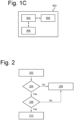
- Figure 2 shows a flowchart schematically depicting a process for a vehicle system in a vehicle for remotely parking or unparking the vehicle according to the present disclosure
- Figure 3 shows an example of the remote device of Figure 1A with a touch screen comprising a valid area for remotely parking or unparking the vehicle.
- Figure 1A shows a user 104 holding a remote device 106 used to remotely assisting parking and unparking a vehicle 102.
- Fig. 1B shows a block diagram of the remote device 106.
- the remote device 106 may comprise a processing unit 902, a memory 904, a communication system 906 and a touch screen interface 908.
- the processing unit 902 is connected to the touch screen interface 908, to the memory 904 and to the communication unit 906.
- the communication system 906 may transmit and receive information via Bluetooth.
- the communication system 906 may as well transmit and receive information through a wireless communication network, for example, a 4G network. However, the communication system 906 may transmit and receive information using any other suitable communication technology.
- the remote device 106 is arranged to performed the method of Figure 7 .
- the vehicle 102 may comprise a vehicle system 802 as shown in Figure 1B .
- the vehicle system 802 may comprise a processing unit 804, a memory 808 connected to the processing unit 804 and a communication system 806 connected to the processing unit 804 and configured to transmit and receive information.
- the communication system 806 may transmit and receive information via Bluetooth.
- the communication system 806 may also transmit and receive information through a wireless communication network, for example, a 4G network, and/or using any other suitable communication technology.
- the vehicle system 802 is arranged to perform the method of Figure 2 .
- the parking space from or to which the user 104 intends to park or unpark the vehicle 102 is between vehicles 108 and 112 such that access to the lateral doors of vehicle 102 is limited or blocked.
- the vehicle system 802 sends, to the remote device 106, first data for triggering a challenge response that needs to be responded to within a certain amount of time given by a first time threshold.
- step 204 of Figure 2 the vehicle system 802 determines whether second data, as a challenge response, has been received from the remote device 106 within the first time threshold. If no challenge response has been received or if it has been received after the first time threshold has expired, the process proceeds to step 206 and the vehicle system 802 controls the vehicle 102 to brake. Otherwise, the process proceeds to step 208 wherein the vehicle system 802 determines whether the challenge response is valid. The validation of the challenge response will be explained with more detail for three different embodiments in relation to Figures 4, 5 , 6A and 6B . If the challenge response is not valid, the process proceeds to step 206 and the vehicle system 802 controls the vehicle 102 to brake.
- the process proceeds to step 210 and the vehicle system 802 controls the vehicle 102 to move.
- the vehicle system 802 may also control the vehicle 102 to brake if the remote device is not located within a certain distance 110 to the vehicle.
- the certain distance may be 5 meters. This ensures that the user can see the vehicle while performing the DMS operation of Figure 2 .
- any other suitable distance that allows the user to see the vehicle 102 can be used.
- Ultra-wideband communication may be used to determine whether the vehicle is within the certain distance while Bluetooth communication may be used to communicate with the remote device.
- any other suitable communications technologies may be used.
- Figure 3 shows the remote device 106 comprising the touch screen 304.
- the touch screen 304 has a height on a vertical direction and a width on a horizontal direction.
- a specific part of the touch screen 304 is a valid area 306 that has a rectangular shape, though the valid area 306 may have any other suitable shape.
- the valid area 306 may be shown as a button and may display some kind of text indicating that an input is expected there.
- Figure 3 illustrates a coordinate system wherein the challenges requests sent in step 202 by the vehicle system 802 of the vehicle 102 requests the anticipated x- and y-position (vertical and horizontal coordinates x and y) of the finger of the user 104 on the touchscreen 304, in a normalized coordinate system.
- the remote device 106 will have to respond to the challenge request within a certain time, otherwise the vehicle 102 will brake (if the vehicle was in movement). If the challenge response is not received, the vehicle 102 will also brake.
- a requirement stating the position of the valid area 306 in the touch screen 304 may come from the vehicle system 802 so that the valid area 306 size or location cannot be changed unless it is agreed.
- the boundary of the valid area 306 can also be defined related to percentages of the remote device touch screen 304, etc.
- a touch position will comprise data of horizontal and vertical coordinates which are respectively the x and y positions of the finger of the user in the touch screen 304 wherein the user input has been received.
- the vertical and horizontal coordinates x and y may be respectively percentages of the touch screen width and height.
- the vertical and horizontal coordinates x and y correspond to the touch position of a finger of a user of the remote device on the touch screen 304.
- the user 104 performs a continuous rub movement within the valid area 306 of the touch screen 304 and, as a response to the challenge request sent in step 202, the remote device 106 sends the current position of the finger on the touch screen.
- the challenge response will comprise information about the touch position on the touch screen 304 of the remote device 106 wherein the touch input corresponding to the rub movement is being received. If, in step 204 of Figure 2 , the challenge response is received on time by the vehicle system 802, and in step 208 the method determines that the challenge response is valid, the vehicle system 802 will control the vehicle 102 to move in step 210. Otherwise, the vehicle system 802 will control the vehicle to brake in step 206.
- the vehicle system 802 in step 208 may determine that the challenge response corresponds to a rub movement by determining whether the touch position is different than a previous touch position corresponding to a previously received challenge response, and whether the touch position is closer than a certain threshold distance from the previous touch position.
- the remote device 106 sends the first data comprising the current position of the finger as a response to the first data.
- the vehicle system 802 validates that the coordinates are within the valid area, that the coordinates are not the same as in the previous challenge response and are within a certain threshold distance from last touch input. In this way, by comparing the current response with the previous response the vehicle system 802 can validate the rub movement.
- FIG 4 schematically illustrates a rub movement on the valid area 306 of the touch screen of the remote device 106.
- the rub movement is performed by the user pressing and slightly rubbing back and forth on a valid area 306 of the touchscreen.
- the motion can be done in any direction and in any part of the valid area 306 of the touchscreen.
- the vehicle 102 will brake if the user 104 keeps the finger static, releases the finger from the touchscreen 304, moves the finger outside the valid area 306 or does a larger motion than the vehicle system 802 anticipates.
- the change in finger position from one reported position to another may not be larger than a certain threshold distance D from the previous touch position.
- x and y represent vertical and horizontal coordinates of the touch screen 304
- i+1 denotes the most recent reported position in the touch screen 304 to validate
- i denotes the last validated position.
- Figure 4 shows an example of a valid area 306 of the touchscreen 304 where the rubbing motion is allowed.
- it is represented as a button, where the user 104 presses down on the dot 404 and rubs in either direction with some restricted allowed distance.
- the vehicle system 802 and the remote device 106 must have a mutual understanding of the valid area 306 of the touchscreen 304 where the rubbing motion is considered an engaged DMS.
- the remote device 106 will always report the x- and y-coordinates of the motion and the vehicle will only actuate longitudinal and lateral control if the reported coordinates are within the valid area 306 and obeys the above equation. This might be done via a normalized coordinate system, where the rubbing area boundary is recognized as percentages of the screen width and height.
- the user 104 may perform a swipe movement on the valid area 306 of the touch screen.
- the vehicle system will considerthat the valid area 306 is divided in a plurality of contiguous zones (zone 1 (511), zone 2 (512), zone 3 (513), zone 4 (514), zone 5 (515) and zone 6 (516) in Figure 5 ) and the swipe movement will be valid if it comprises pressing down on a first zone among the contiguous zones, continuously moving a finger into subsequent zones and continuously moving the finger back after reaching a final zone among the contiguous zones.
- the vehicle system 802 sends first data to the remote device 106 in step 202 of Figure 2 .
- the remote device sends second data as a challenge response comprising information about a touch position on the touch screen 304 of the remote device 106 wherein a touch input has been received.
- the vehicle system 802 will control the vehicle to move in step 210. Otherwise, the vehicle system 802 will control the vehicle to brake in step 206, in case the vehicle was already in movement.
- the vehicle system 802 in step 208 may determine that the challenge response corresponds to the expected swipe movement by comparing the touch position with a previous touch position corresponding to a previously received challenge response.
- the expected swipe movement may comprise continuously moving a finger from one contiguous zone to the next within an expected amount of time than is less than a first time threshold and more than a second time threshold.
- the expected swipe movement may comprise skipping one or two zones.
- the DMS is engaged by performing a swiping motion across a valid area 306 of the touchscreen 304 of the remote device 106 from left to right or right to left, depending on the user's choice.
- the freedom to choose direction only applies when the user starts the motion between the far left and far right area, e.g. between zone 2 (512) and zone 5 (515) as depicted in Figure 5 .
- zone 1 (511) and zone 6 (516) as in Figure 5 .
- Figure 5 shows a swiping direction parallel to one side of the valid area
- the swiping movement may be performed in any direction even if no parallel to the side of the valid area.
- the vehicle brakes if the user releases the finger from the touch screen 304, keeps it still for too long, changes direction of the motion at a point other than the turning points, is outside the valid area 306, or does not perform the anticipated motion correctly, e.g. being slower or faster than the vehicle anticipates.
- the vehicle system 802 validates the swiping motion by anticipating that the user moves their finger across the swiping area through a set number of zones, only known to the vehicle system. By putting constraints on how long the user is allowed to stay inside a zone and how many zones the user can skip, the anticipated motion can be validated. In addition, the user may not keep their finger still for too long and the user must continue swiping in the direction that they chose when the DMS was initially engaged. As said, an example of such a swiping area, divided into six zones is depicted in Figure 5 . Some kind of visual indication may be provided to the user to indicate that some zones can be skipped. For instance, in Figure 5 , this is indicated with a gradient indicates that zone 2 (512) and zone 3 (513) can be skipped, but skipping zone 5 (515) or zone 6 (516) would result in movement too fast and the vehicle would brake.
- zone 1 the user has pressed down in zone 1 (511) and moved their finger into zone 2 (512), zone 3 (513)and so forth until zone 6 (516) where the user stops and continuously moves their finger back into zone 1 (511).
- zone 6 the user stops and continuously moves their finger back into zone 1 (511).
- the time it takes for the user to traverse each zone would be the anticipated tempo. It is fine to skip one or two zones, i.e., being a bit faster than what is anticipated, but not more. Conversely, it is fine to be a bit slower than the anticipated tempo, but the user cannot stay in one zone for too long.
- the user 104 may keep a touch on the valid area 306 of the touch screen 304 and at the same time keep the remote device 106 in a position such that the remote device 106 forms an angle with the ground within a tilt range.
- the tilt range may be between zero degrees and 90 degrees.
- the vehicle system 802 will send first data to the remote device 106.
- the vehicle system will check whether second data as a challenge response from the remote device has been received within a predetermined time from the transmission of the first data. If the second data is received within the predetermined time, the method of Figure 2 proceeds to step 208 wherein the vehicle system determines whether the challenge response is valid.
- the received second data in the third embodiment comprises a first information about a touch position on the touch screen 304 of the remote device 106 wherein the touch input has been received and second information indicating a position of the remote device in relation to ground. If in step 208, the vehicle system 802 determines that the received touch position is within a range from a previous touch position corresponding to a previously received challenge response, that the second information indicates than the position of the remote device is different than a previous position indicated in a previously received second information, and that the remote device forms an angle with the ground within the tilt range, then the vehicle system 802 will control the vehicle 102 to move in step 210. Otherwise, the vehicle system 802 will control the vehicle to brake in step 206.
- Fig. 6A shows the remote device 106 is in a position forming an angle with the ground that is between zero and 90 degrees.
- 604 represents a horizontal axis that is parallel to the ground while 602 represents a vertical axis that is perpendicular to the ground.
- the user must keep the finger within the valid area 306 (for instance, on the spot 610 of the valid area 306 but it might be in any other part of the valid area) at the same time that keeps the remote device in an angle with the ground within a tilt range. During operation the user keeps the remote device within the tilt range and only presses the button, such that he or she can focus on the environment.
- the second information which may be provided by a gravity sensor of the remote device will fluctuate even when the user is not actively doing a tilting movement.
- the fluctuations are used such that the second information sent as a challenge response to the first data is not the same as the previous one.
- the second information is used by the vehicle system 802 to check that each challenge response is new.
- the touch input is in the same area 610 and if an error appear and the vehicle does not brake when the finger is removed, the user can brake by moving the remote device outside of the predetermined tilt range.
- Figure 6B schematically illustrates a verification step of the gravity sensor performed by the remote device 106.
- the remote device may perform the verification step to validate the gravity sensor of the remote device and verify the tilt range before performing the method of Fig. 2 .
- the user 104 tilts the remote device 106 continuously backward and forward following arc 606 from a first position wherein the remote device may form a first angle of 90 degrees with the ground plane and a second position wherein the remote device may form a second angle of zero degrees with the ground plane.
- the verification step may utilize the gravity property of the remote device operating system that combines the accelerometer, magnetometer and gyroscope sensor in the device hardware. The gravity property is used to determine how the remote device is oriented in 3-dimensional space.
- the user is required to tilt the remote device. Instructions on how the tilt is performed may be shown on the touch screen 304.
- the vehicle system knows that the user intends to launch maneuver and can verify that the remote device sensors (touch and gravity) are working as intended.
- the vehicle system can verify that it is not malfunctioning in a way that it unintentionally registers presses. After confirmation it is highly unlikely that both touch and gravity sensors would start malfunctioning in a dangerous way during a maneuver.
- the two mechanisms complement each other as the second information is highly fluctuating while the valid area press value can be very static depending on usage. Information on how to properly engage the DMS and how to brake via releasing the DMS will be conveyed to the user prior to the maneuver.
- Figure 7 illustrates a flowchart schematically depicting a process for a remote device for remotely parking or unparking a vehicle according to the present disclosure.
- the remote device 106 receives first data for triggering a challenge response from a vehicle system.
- the remote device receives a touch input in the touch screen 304.
- the remote device transmits as a challenge response second data comprising x and y coordinates of the touch input on the touch screen 304.
- processors e.g., one or more microprocessors including central processing units (CPU)
- memory which may include stored operating system software, firmware and/or application software executable by the processor(s) for controlling operation thereof and/or for performing the particular algorithms represented by the various functions and/or operations described herein, including interaction between and/or cooperation with each other as well as transmitters and receivers.
- processors may be included in a single ASIC (Application-Specific Integrated Circuitry), or several processors and various digital hardware may be distributed among several separate components, whether individually packaged or assembled into a SoC (System-on-a-Chip).
- ASIC Application-Specific Integrated Circuitry
- SoC System-on-a-Chip
- the systems, methods and components described, and/or any other arrangement, unit, system, device or module described herein may for instance be implemented in one or several arbitrary nodes comprised in the host vehicle and/or one or more separate devices.
- a node may comprise an electronic control unit (ECU) or any suitable electronic device, which may be a main or central node.
- ECU electronice control unit
- the these may further comprise or be arranged or configured to cooperate with any type of storage device or storage arrangement known in the art, which may for example be used for storing input or output data associated with the functions and/or operations described herein.
- the systems, components and methods described herein may further comprise any computer hardware and software and/or electrical hardware known in the art configured to enable communication there between.
Landscapes
- Engineering & Computer Science (AREA)
- Physics & Mathematics (AREA)
- General Physics & Mathematics (AREA)
- General Engineering & Computer Science (AREA)
- Theoretical Computer Science (AREA)
- Human Computer Interaction (AREA)
- Chemical & Material Sciences (AREA)
- Combustion & Propulsion (AREA)
- Transportation (AREA)
- Mechanical Engineering (AREA)
- Aviation & Aerospace Engineering (AREA)
- Radar, Positioning & Navigation (AREA)
- Remote Sensing (AREA)
- Automation & Control Theory (AREA)
- Selective Calling Equipment (AREA)
Priority Applications (3)
| Application Number | Priority Date | Filing Date | Title |
|---|---|---|---|
| EP23205897.4A EP4545381A1 (de) | 2023-10-25 | 2023-10-25 | Verfahren und systeme zur fernunterstützung beim einparken oder ausparken eines fahrzeugs |
| CN202411467411.1A CN119889081A (zh) | 2023-10-25 | 2024-10-21 | 用于远程辅助车辆泊车或解除泊车的方法和系统 |
| US18/923,750 US20250138543A1 (en) | 2023-10-25 | 2024-10-23 | Methods and systems for remotely assisting parking or unparking a vehicle |
Applications Claiming Priority (1)
| Application Number | Priority Date | Filing Date | Title |
|---|---|---|---|
| EP23205897.4A EP4545381A1 (de) | 2023-10-25 | 2023-10-25 | Verfahren und systeme zur fernunterstützung beim einparken oder ausparken eines fahrzeugs |
Publications (1)
| Publication Number | Publication Date |
|---|---|
| EP4545381A1 true EP4545381A1 (de) | 2025-04-30 |
Family
ID=88511015
Family Applications (1)
| Application Number | Title | Priority Date | Filing Date |
|---|---|---|---|
| EP23205897.4A Pending EP4545381A1 (de) | 2023-10-25 | 2023-10-25 | Verfahren und systeme zur fernunterstützung beim einparken oder ausparken eines fahrzeugs |
Country Status (3)
| Country | Link |
|---|---|
| US (1) | US20250138543A1 (de) |
| EP (1) | EP4545381A1 (de) |
| CN (1) | CN119889081A (de) |
Citations (3)
| Publication number | Priority date | Publication date | Assignee | Title |
|---|---|---|---|---|
| US11067978B2 (en) * | 2016-12-19 | 2021-07-20 | Clarion Co., Ltd. | Terminal and method for controlling terminal |
| US20210269092A1 (en) * | 2020-02-28 | 2021-09-02 | Ford Global Technologies, Llc | User engagement switch for remote trailer maneuvering |
| DE102020113382A1 (de) * | 2020-05-18 | 2021-11-18 | Bayerische Motoren Werke Aktiengesellschaft | Aktivieren eines automatisierten Parkmanövers mittels einer mit einem mobilen Kommunikationsgerät durchgeführten Aktivierungsbewegung |
Family Cites Families (5)
| Publication number | Priority date | Publication date | Assignee | Title |
|---|---|---|---|---|
| JP7159579B2 (ja) * | 2017-11-01 | 2022-10-25 | ソニーグループ株式会社 | 医療用保持装置、及び医療用アームシステム |
| US11137754B2 (en) * | 2018-10-24 | 2021-10-05 | Ford Global Technologies, Llc | Intermittent delay mitigation for remote vehicle operation |
| JP7409878B2 (ja) * | 2020-01-09 | 2024-01-09 | 本田技研工業株式会社 | 車両制御装置 |
| US20220229432A1 (en) * | 2021-01-21 | 2022-07-21 | Ford Global Technologies, Llc | Autonomous vehicle camera interface for wireless tethering |
| US12097843B2 (en) * | 2021-11-24 | 2024-09-24 | Ford Global Technologies, Llc | Remote park assist augmented reality user engagement with cameraless detection |
-
2023
- 2023-10-25 EP EP23205897.4A patent/EP4545381A1/de active Pending
-
2024
- 2024-10-21 CN CN202411467411.1A patent/CN119889081A/zh active Pending
- 2024-10-23 US US18/923,750 patent/US20250138543A1/en active Pending
Patent Citations (3)
| Publication number | Priority date | Publication date | Assignee | Title |
|---|---|---|---|---|
| US11067978B2 (en) * | 2016-12-19 | 2021-07-20 | Clarion Co., Ltd. | Terminal and method for controlling terminal |
| US20210269092A1 (en) * | 2020-02-28 | 2021-09-02 | Ford Global Technologies, Llc | User engagement switch for remote trailer maneuvering |
| DE102020113382A1 (de) * | 2020-05-18 | 2021-11-18 | Bayerische Motoren Werke Aktiengesellschaft | Aktivieren eines automatisierten Parkmanövers mittels einer mit einem mobilen Kommunikationsgerät durchgeführten Aktivierungsbewegung |
Also Published As
| Publication number | Publication date |
|---|---|
| CN119889081A (zh) | 2025-04-25 |
| US20250138543A1 (en) | 2025-05-01 |
Similar Documents
| Publication | Publication Date | Title |
|---|---|---|
| CN109398357B (zh) | 车辆控制装置、车辆、车辆控制方法以及存储介质 | |
| JP6835219B2 (ja) | 駐車制御方法及び駐車制御装置 | |
| KR102463740B1 (ko) | 자율주차보조장치 및 그의 주차 지원 방법 | |
| KR102299496B1 (ko) | 차량의 자율 주행 제어 장치 및 방법, 그리고 차량 시스템 | |
| US10883596B2 (en) | Remote vehicle control | |
| JP6930606B2 (ja) | 駐車制御方法及び駐車制御装置 | |
| US20200324816A1 (en) | Method for Controlling a Parking Operation of a Motor Vehicle | |
| JP7067567B2 (ja) | 駐車制御方法及び駐車制御装置 | |
| KR102610748B1 (ko) | 차량의 군집 주행을 위한 사용자 인터페이스 제공 장치 및 방법 | |
| US11789442B2 (en) | Anomalous input detection | |
| JP6927330B2 (ja) | 駐車制御方法及び駐車制御装置 | |
| CN109987086A (zh) | 远程停车控制装置、包括该装置的系统及其方法 | |
| US20200393826A1 (en) | Remote trailer maneuver-assist | |
| US20210309217A1 (en) | Apparatus for controlling autonomous driving of a vehicle, system having the same and method thereof | |
| EP3838703B1 (de) | Autonomes steuergerät und steuerverfahren | |
| CN115515842B (zh) | 通过以移动通信设备执行的激活移动来激活自动泊车操作 | |
| US20200393825A1 (en) | Remote trailer maneuver-assist | |
| US20190286118A1 (en) | Remote vehicle control device and remote vehicle control method | |
| KR20210079181A (ko) | 자율 주행 제어 장치, 그를 포함한 차량 시스템 및 그 방법 | |
| EP4545381A1 (de) | Verfahren und systeme zur fernunterstützung beim einparken oder ausparken eines fahrzeugs | |
| CN112896174B (zh) | 用于判断驾驶员的转向意图的设备和方法及系统 | |
| US12498230B2 (en) | Autonomous vehicle, control system for remotely controlling the same, and method thereof | |
| US12515658B2 (en) | Moving body operation system | |
| KR20220141375A (ko) | 주차 제어 장치 및 그 방법 | |
| CN115220579B (zh) | 车载终端控制方法以及装置 |
Legal Events
| Date | Code | Title | Description |
|---|---|---|---|
| PUAI | Public reference made under article 153(3) epc to a published international application that has entered the european phase |
Free format text: ORIGINAL CODE: 0009012 |
|
| STAA | Information on the status of an ep patent application or granted ep patent |
Free format text: STATUS: THE APPLICATION HAS BEEN PUBLISHED |
|
| AK | Designated contracting states |
Kind code of ref document: A1 Designated state(s): AL AT BE BG CH CY CZ DE DK EE ES FI FR GB GR HR HU IE IS IT LI LT LU LV MC ME MK MT NL NO PL PT RO RS SE SI SK SM TR |
|
| STAA | Information on the status of an ep patent application or granted ep patent |
Free format text: STATUS: REQUEST FOR EXAMINATION WAS MADE |
|
| 17P | Request for examination filed |
Effective date: 20251030 |