EP4545384A2 - Système de stockage automatisé avec système de plaque modulaire monté sur un cadre et agencement de renforcement - Google Patents
Système de stockage automatisé avec système de plaque modulaire monté sur un cadre et agencement de renforcement Download PDFInfo
- Publication number
- EP4545384A2 EP4545384A2 EP24223662.8A EP24223662A EP4545384A2 EP 4545384 A2 EP4545384 A2 EP 4545384A2 EP 24223662 A EP24223662 A EP 24223662A EP 4545384 A2 EP4545384 A2 EP 4545384A2
- Authority
- EP
- European Patent Office
- Prior art keywords
- plate
- storage
- members
- plate members
- framework structure
- Prior art date
- Legal status (The legal status is an assumption and is not a legal conclusion. Google has not performed a legal analysis and makes no representation as to the accuracy of the status listed.)
- Pending
Links
Images





Classifications
-
- B—PERFORMING OPERATIONS; TRANSPORTING
- B65—CONVEYING; PACKING; STORING; HANDLING THIN OR FILAMENTARY MATERIAL
- B65G—TRANSPORT OR STORAGE DEVICES, e.g. CONVEYORS FOR LOADING OR TIPPING, SHOP CONVEYOR SYSTEMS OR PNEUMATIC TUBE CONVEYORS
- B65G1/00—Storing articles, individually or in orderly arrangement, in warehouses or magazines
- B65G1/02—Storage devices
- B65G1/04—Storage devices mechanical
- B65G1/0464—Storage devices mechanical with access from above
-
- B—PERFORMING OPERATIONS; TRANSPORTING
- B65—CONVEYING; PACKING; STORING; HANDLING THIN OR FILAMENTARY MATERIAL
- B65G—TRANSPORT OR STORAGE DEVICES, e.g. CONVEYORS FOR LOADING OR TIPPING, SHOP CONVEYOR SYSTEMS OR PNEUMATIC TUBE CONVEYORS
- B65G1/00—Storing articles, individually or in orderly arrangement, in warehouses or magazines
- B65G1/02—Storage devices
- B65G1/04—Storage devices mechanical
- B65G1/0492—Storage devices mechanical with cars adapted to travel in storage aisles
-
- A—HUMAN NECESSITIES
- A62—LIFE-SAVING; FIRE-FIGHTING
- A62C—FIRE-FIGHTING
- A62C3/00—Fire prevention, containment or extinguishing specially adapted for particular objects or places
- A62C3/002—Fire prevention, containment or extinguishing specially adapted for particular objects or places for warehouses, storage areas or other installations for storing goods
-
- B—PERFORMING OPERATIONS; TRANSPORTING
- B62—LAND VEHICLES FOR TRAVELLING OTHERWISE THAN ON RAILS
- B62D—MOTOR VEHICLES; TRAILERS
- B62D33/00—Superstructures for load-carrying vehicles
- B62D33/04—Enclosed load compartments ; Frameworks for movable panels, tarpaulins or side curtains
- B62D33/048—Enclosed load compartments ; Frameworks for movable panels, tarpaulins or side curtains for refrigerated goods vehicles
-
- B—PERFORMING OPERATIONS; TRANSPORTING
- B62—LAND VEHICLES FOR TRAVELLING OTHERWISE THAN ON RAILS
- B62D—MOTOR VEHICLES; TRAILERS
- B62D63/00—Motor vehicles or trailers not otherwise provided for
- B62D63/02—Motor vehicles
- B62D63/025—Modular vehicles
-
- B—PERFORMING OPERATIONS; TRANSPORTING
- B65—CONVEYING; PACKING; STORING; HANDLING THIN OR FILAMENTARY MATERIAL
- B65G—TRANSPORT OR STORAGE DEVICES, e.g. CONVEYORS FOR LOADING OR TIPPING, SHOP CONVEYOR SYSTEMS OR PNEUMATIC TUBE CONVEYORS
- B65G1/00—Storing articles, individually or in orderly arrangement, in warehouses or magazines
- B65G1/02—Storage devices
- B65G1/04—Storage devices mechanical
- B65G1/0471—Storage devices mechanical with access from beneath
-
- B—PERFORMING OPERATIONS; TRANSPORTING
- B65—CONVEYING; PACKING; STORING; HANDLING THIN OR FILAMENTARY MATERIAL
- B65G—TRANSPORT OR STORAGE DEVICES, e.g. CONVEYORS FOR LOADING OR TIPPING, SHOP CONVEYOR SYSTEMS OR PNEUMATIC TUBE CONVEYORS
- B65G1/00—Storing articles, individually or in orderly arrangement, in warehouses or magazines
- B65G1/02—Storage devices
- B65G1/04—Storage devices mechanical
- B65G1/0478—Storage devices mechanical for matrix-arrangements
-
- B—PERFORMING OPERATIONS; TRANSPORTING
- B65—CONVEYING; PACKING; STORING; HANDLING THIN OR FILAMENTARY MATERIAL
- B65G—TRANSPORT OR STORAGE DEVICES, e.g. CONVEYORS FOR LOADING OR TIPPING, SHOP CONVEYOR SYSTEMS OR PNEUMATIC TUBE CONVEYORS
- B65G1/00—Storing articles, individually or in orderly arrangement, in warehouses or magazines
- B65G1/02—Storage devices
- B65G1/04—Storage devices mechanical
- B65G1/06—Storage devices mechanical with means for presenting articles for removal at predetermined position or level
- B65G1/065—Storage devices mechanical with means for presenting articles for removal at predetermined position or level with self propelled cars
-
- B—PERFORMING OPERATIONS; TRANSPORTING
- B65—CONVEYING; PACKING; STORING; HANDLING THIN OR FILAMENTARY MATERIAL
- B65G—TRANSPORT OR STORAGE DEVICES, e.g. CONVEYORS FOR LOADING OR TIPPING, SHOP CONVEYOR SYSTEMS OR PNEUMATIC TUBE CONVEYORS
- B65G1/00—Storing articles, individually or in orderly arrangement, in warehouses or magazines
- B65G1/02—Storage devices
- B65G1/04—Storage devices mechanical
- B65G1/137—Storage devices mechanical with arrangements or automatic control means for selecting which articles are to be removed
- B65G1/1373—Storage devices mechanical with arrangements or automatic control means for selecting which articles are to be removed for fulfilling orders in warehouses
-
- B—PERFORMING OPERATIONS; TRANSPORTING
- B65—CONVEYING; PACKING; STORING; HANDLING THIN OR FILAMENTARY MATERIAL
- B65G—TRANSPORT OR STORAGE DEVICES, e.g. CONVEYORS FOR LOADING OR TIPPING, SHOP CONVEYOR SYSTEMS OR PNEUMATIC TUBE CONVEYORS
- B65G2201/00—Indexing codes relating to handling devices, e.g. conveyors, characterised by the type of product or load being conveyed or handled
- B65G2201/02—Articles
- B65G2201/0235—Containers
- B65G2201/0258—Trays, totes or bins
-
- B—PERFORMING OPERATIONS; TRANSPORTING
- B65—CONVEYING; PACKING; STORING; HANDLING THIN OR FILAMENTARY MATERIAL
- B65G—TRANSPORT OR STORAGE DEVICES, e.g. CONVEYORS FOR LOADING OR TIPPING, SHOP CONVEYOR SYSTEMS OR PNEUMATIC TUBE CONVEYORS
- B65G2207/00—Indexing codes relating to constructional details, configuration and additional features of a handling device, e.g. Conveyors
- B65G2207/22—Heat or fire protection
-
- E—FIXED CONSTRUCTIONS
- E04—BUILDING
- E04B—GENERAL BUILDING CONSTRUCTIONS; WALLS, e.g. PARTITIONS; ROOFS; FLOORS; CEILINGS; INSULATION OR OTHER PROTECTION OF BUILDINGS
- E04B1/00—Constructions in general; Structures which are not restricted either to walls, e.g. partitions, or floors or ceilings or roofs
- E04B1/18—Structures comprising elongated load-supporting parts, e.g. columns, girders, skeletons
- E04B1/24—Structures comprising elongated load-supporting parts, e.g. columns, girders, skeletons the supporting parts consisting of metal
- E04B1/2403—Connection details of the elongated load-supporting parts
- E04B2001/2415—Brackets, gussets, joining plates
-
- E—FIXED CONSTRUCTIONS
- E04—BUILDING
- E04B—GENERAL BUILDING CONSTRUCTIONS; WALLS, e.g. PARTITIONS; ROOFS; FLOORS; CEILINGS; INSULATION OR OTHER PROTECTION OF BUILDINGS
- E04B1/00—Constructions in general; Structures which are not restricted either to walls, e.g. partitions, or floors or ceilings or roofs
- E04B1/18—Structures comprising elongated load-supporting parts, e.g. columns, girders, skeletons
- E04B1/24—Structures comprising elongated load-supporting parts, e.g. columns, girders, skeletons the supporting parts consisting of metal
- E04B1/2403—Connection details of the elongated load-supporting parts
- E04B2001/2439—Adjustable connections, e.g. using elongated slots or threaded adjustment elements
-
- E—FIXED CONSTRUCTIONS
- E04—BUILDING
- E04B—GENERAL BUILDING CONSTRUCTIONS; WALLS, e.g. PARTITIONS; ROOFS; FLOORS; CEILINGS; INSULATION OR OTHER PROTECTION OF BUILDINGS
- E04B1/00—Constructions in general; Structures which are not restricted either to walls, e.g. partitions, or floors or ceilings or roofs
- E04B1/18—Structures comprising elongated load-supporting parts, e.g. columns, girders, skeletons
- E04B1/24—Structures comprising elongated load-supporting parts, e.g. columns, girders, skeletons the supporting parts consisting of metal
- E04B2001/2481—Details of wall panels
Definitions
- the present invention relates to an automated storage and retrieval system for the storage and retrieval of containers, in particular to arrangements for stabilizing a framework structure of such a storage and retrieval system.
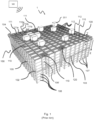
- Fig. 1 discloses a typical prior art automated storage and retrieval system 1 with a framework structure 100 and Fig. 2 and 3 disclose two different prior art container handling vehicles 201,301 suitable for operating on such a system 1.
- the framework structure 100 comprises upright members 102, horizontal members 103 and a storage volume comprising storage columns 105 arranged in rows between the upright members 102 and the horizontal members 103.
- storage columns 105 storage containers 106, also known as bins, are stacked one on top of one another to form stacks 107.
- the members 102, 103 may typically be made of metal, e.g. extruded aluminum profiles.
- the framework structure 100 of the automated storage and retrieval system 1 comprises a rail system 108 arranged across the top of framework structure 100, on which rail system 108 a plurality of container handling vehicles 201,301 are operated to raise storage containers 106 from, and lower storage containers 106 into, the storage columns 105, and also to transport the storage containers 106 above the storage columns 105.
- the rail system 108 comprises a first set of parallel rails 110 arranged to guide movement of the container handling vehicles 201,301 in a first direction X across the top of the frame structure 100, and a second set of parallel rails 111 arranged perpendicular to the first set of rails 110 to guide movement of the container handling vehicles 201,301 in a second direction Y which is perpendicular to the first direction X.
- Containers 106 stored in the columns 105 are accessed by the container handling vehicles through access openings 112 in the rail system 108.
- the container handling vehicles 201,301 can move laterally above the storage columns 105, i.e. in a plane which is parallel to the horizontal X-Y plane.
- the upright members 102 of the framework structure 100 may be used to guide the storage containers during raising of the containers out from and lowering of the containers into the columns 105.
- the stacks 107 of containers 106 are typically self-supportive.
- Each prior art container handling vehicle 201,301 comprises a vehicle body 201a,301a, and first and second sets of wheels 201b,301b,201c,301c which enable the lateral movement of the container handling vehicles 201,301 in the X direction and in the Y direction, respectively.
- first and second sets of wheels 201b,301b,201c,301c which enable the lateral movement of the container handling vehicles 201,301 in the X direction and in the Y direction, respectively.
- the first set of wheels 201b,301b is arranged to engage with two adjacent rails of the first set 110 of rails
- the second set of wheels 201c,301c is arranged to engage with two adjacent rails of the second set 111 of rails.
- At least one of the sets of wheels 201b,301b,201c,301c can be lifted and lowered, so that the first set of wheels 201b,301b and/or the second set of wheels 201c,301c can be engaged with the respective set of rails 110, 111 at any one time.
- Each prior art container handling vehicle 201,301 also comprises a lifting device (not shown) for vertical transportation of storage containers 106, e.g. raising a storage container 106 from, and lowering a storage container 106 into, a storage column 105.
- the lifting device comprises one or more gripping / engaging devices which are adapted to engage a storage container 106, and which gripping / engaging devices can be lowered from the vehicle 201,301 so that the position of the gripping / engaging devices with respect to the vehicle 201,301 can be adjusted in a third direction Z which is orthogonal the first direction X and the second direction Y.
- Parts of the gripping device of the container handling vehicle 301 are shown in fig. 3 indicated with reference number 304.
- the gripping device of the container handling device 201 is located within the vehicle body 301a in Fig. 2 .
- the storage volume of the framework structure 100 has often been referred to as a grid 104, where the possible storage positions within this grid are referred to as storage cells.
- Each storage column may be identified by a position in an X- and Y-direction, while each storage cell may be identified by a container number in the X-, Y and Z-direction.
- Each prior art container handling vehicle 201,301 comprises a storage compartment or space for receiving and stowing a storage container 106 when transporting the storage container 106 across the rail system 108.
- the storage space may comprise a cavity arranged centrally within the vehicle body 201a as shown in Fig. 2 and as described in e.g. WO2015/193278A1 , the contents of which are incorporated herein by reference.
- Fig. 3 shows an alternative configuration of a container handling vehicle 301 with a cantilever construction.
- a container handling vehicle 301 with a cantilever construction.
- Such a vehicle is described in detail in e.g. NO317366 , the contents of which are also incorporated herein by reference.
- the central cavity container handling vehicles 201 shown in Fig. 2 may have a footprint that covers an area with dimensions in the X and Y directions which is generally equal to the lateral extent of a storage column 105, e.g. as is described in WO2015/193278A1 , the contents of which are incorporated herein by reference.
- the term 'lateral' used herein may mean 'horizontal'.
- the central cavity container handling vehicles 101 may have a footprint which is larger than the lateral area defined by a storage column 105, e.g. as is disclosed in WO2014/090684A1 .
- the rail system 108 typically comprises rails with grooves in which the wheels of the vehicles run.
- the rails may comprise upwardly protruding elements, where the wheels of the vehicles comprise flanges to prevent derailing. These grooves and upwardly protruding elements are collectively known as tracks.
- Each rail may comprise one track, or each rail may comprise two parallel tracks.
- WO2018146304 illustrates a typical configuration of rail system 108 comprising rails and parallel tracks in both X and Y directions.
- columns 105 In the framework structure 100, a majority of the columns 105 are storage columns 105, i.e. columns 105 where storage containers 106 are stored in stacks 107. However, some columns 105 may have other purposes.
- columns 119 and 120 are such special-purpose columns used by the container handling vehicles 201,301 to drop off and/or pick up storage containers 106 so that they can be transported to an access station (not shown) where the storage containers 106 can be accessed from outside of the framework structure 100 or transferred out of or into the framework structure 100.
- such a location is normally referred to as a 'port' and the column in which the port is located may be referred to as a 'port column' 119,120.
- the transportation to the access station may be in any direction, that is horizontal, tilted and/or vertical.
- the storage containers 106 may be placed in a random or dedicated column 105 within the framework structure 100, then picked up by any container handling vehicle and transported to a port column 119,120 for further transportation to an access station.
- 'tilted' means transportation of storage containers 106 having a general transportation orientation somewhere between horizontal and vertical.
- the first port column 119 may for example be a dedicated drop-off port column where the container handling vehicles 201,301 can drop off storage containers 106 to be transported to an access or a transfer station
- the second port column 120 may be a dedicated pick-up port column where the container handling vehicles 201,301 can pick up storage containers 106 that have been transported from an access or a transfer station.
- the access station may typically be a picking or a stocking station where product items are removed from or positioned into the storage containers 106.
- the storage containers 106 are normally not removed from the automated storage and retrieval system 1, but are returned into the framework structure 100 again once accessed.
- a port can also be used for transferring storage containers to another storage facility (e.g. to another framework structure or to another automated storage and retrieval system), to a transport vehicle (e.g. a train or a lorry), or to a production facility.
- a conveyor system comprising conveyors is normally employed to transport the storage containers between the port columns 119,120 and the access station.
- the conveyor system may comprise a lift device with a vertical component for transporting the storage containers 106 vertically between the port column 119,120 and the access station.
- the conveyor system may be arranged to transfer storage containers 106 between different framework structures, e.g. as is described in WO2014/075937A1 , the contents of which are incorporated herein by reference.
- one of the container handling vehicles 201,301 is instructed to retrieve the target storage container 106 from its position and transport it to the drop-off port column 119.
- This operation involves moving the container handling vehicle 201,301 to a location above the storage column 105 in which the target storage container 106 is positioned, retrieving the storage container 106 from the storage column 105 using the container handling vehicle's 201,301 lifting device (not shown), and transporting the storage container 106 to the drop-off port column 119. If the target storage container 106 is located deep within a stack 107, i.e.
- the operation also involves temporarily moving the above-positioned storage containers prior to lifting the target storage container 106 from the storage column 105.
- This step which is sometimes referred to as "digging" within the art, may be performed with the same container handling vehicle that is subsequently used for transporting the target storage container to the drop-off port column 119, or with one or a plurality of other cooperating container handling vehicles.
- the automated storage and retrieval system 1 may have container handling vehicles specifically dedicated to the task of temporarily removing storage containers from a storage column 105. Once the target storage container 106 has been removed from the storage column 105, the temporarily removed storage containers can be repositioned into the original storage column 105. However, the removed storage containers may alternatively be relocated to other storage columns.
- one of the container handling vehicles 201,301 When a storage container 106 is to be stored in one of the columns 105, one of the container handling vehicles 201,301 is instructed to pick up the storage container 106 from the pick-up port column 120 and transport it to a location above the storage column 105 where it is to be stored. After any storage containers positioned at or above the target position within the storage column stack 107 have been removed, the container handling vehicle 201,301 positions the storage container 106 at the desired position. The removed storage containers may then be lowered back into the storage column 105, or relocated to other storage columns.
- the automated storage and retrieval system 1 For monitoring and controlling the automated storage and retrieval system 1, e.g. monitoring and controlling the location of respective storage containers 106 within the framework structure 100, the content of each storage container 106; and the movement of the container handling vehicles 201,301 so that a desired storage container 106 can be delivered to the desired location at the desired time without the container handling vehicles 201,301 colliding with each other, the automated storage and retrieval system 1 comprises a control system 500 which typically is computerized and which typically comprises a database for keeping track of the storage containers 106.
- the framework of an automated storage and retrieval system as described above must of course be able to support the weight of the framework itself, together with the combined weight of the storage containers and their contents, the container handling vehicles and other equipment of the system.
- the framework must also be able to withstand lateral forces, for example caused by the acceleration and braking of the vehicles, uneven weight distribution, earthquake and the like.
- Prior art storage systems have employed various arrangements to ensure sufficient stability of the framework structure 100.
- the framework structure is connected to and supported by the walls of the building in which the storage system is housed.
- the prior art storage systems may dependent on an auxiliary supporting structure (not shown) constructed at least partly along the periphery of the framework structure 100.
- the requirement of having an auxiliary supporting structure is disadvantageous for a number of reasons.
- the supporting structure occupies space/area which could otherwise be utilized by the storage system, i.e. it prevents optimum use of available space/area for storage; the need of an auxiliary supporting structure may limit the available options for positioning of the storage system, i.e. the auxiliary supporting structure may prevent the optimum positioning of the storage system since the auxiliary supporting structure itself often requires connection to a surrounding structure, such as the inner walls of a building; and the requirement of a supporting structure is not cost efficient.
- WO 2019101367 a system of inclined supporting struts connected to the upright members 102 of the framework structure. While the struts from WO 2019101367 provide stability and allow the framework structure to be self-supporting, there is room for improvement in providing a simpler and more flexible arrangement for stabilizing the framework structure 100.
- the solution described in WO 20191010367 does not provide a modular system where functional plate members can be installed that perform various functions.
- WO 2019101367 One particular disadvantage for the arrangement described in WO 2019101367 is that installation of the struts depends upon a new and somewhat more complicated profile of the upright members 102 of the framework structure.
- the upright members themselves are hollow, extruded aluminum profiles.
- the upright members have four corner sections 8, each of which having two perpendicular container-guiding plates 9. When in use, corners 11 of the containers slide upward and downward along the storage column 105, guided by the corner sections 8 of the upright members.
- WO requires a groove or ridge in the space between container guiding plates 9, to which an attachment device for the struts are connected. This requirement for a more complicated profile for the upright members increases cost and prohibits the use of the struts in existing installations.
- This application describes a storage and retrieval system comprising a framework structure defining storage columns in which are stacked storage containers.
- An empty column is arranged adjacent to one of the four sides of a storage column.
- a containing-retrieving vehicle travels up and down the empty column and removes storage containers sideways from the adjacent side of the storage column.
- the application describes panels installed along the three other faces of the storage column, said panels being described as providing structural stability for the framework.
- Each of the panels has an inward facing lip, such that three panels of a given vertical level of the column form a shelf on which a container rests and from which the container is removed sideways by the vehicle.
- WO2016/172793 Since the lips of the panels form the shelves on which the containers rest, the panels in WO2016/172793 must be installed as part of the original construction of the framework. The panels likewise cannot be removed or replaced while containers are arranged in the storage columns, and WO2016/172793 does not offer a modular system where functional panels can be installed at various locations in the framework to create functional ones, as the supporting panels of WO2016/172793 must be at every storage column.
- the invention is a modular plate system where plate members of various functions can be easily inserted between the upright members of the framework structure of a storage and retrieval system as described above.
- the modular plate system of the invention may function as a stabilizing arrangement for the framework structure.
- the plate members of the system are bracing plate members that may be connected between adjacent upright members 102 of a framework structure 100 as described above in order to provide structural stability for the framework.
- the plate members may provide some function other than or in addition to stabilization, for example, the functional plate members may be thermally insulated plates, fire barrier plates, sound insulated plates and the like, whereby the plates may be used to form zones or barriers in the framework, for example for forming a refrigerated zone, a sound insulated zone or a fire barrier wall for creating a fire protected zone.
- the plates may be easily installed and removed, allowing functional zones to be created, expanded or repurposed at will.
- the invention is directed to a method of stabilizing a framework structure of a storage and retrieval system.
- the invention is directed to a method of creating functional zones in a framework structure of a storage and retrieval system.
- the framework structure 100 of the automated storage and retrieval system 1 is constructed in accordance with the prior art framework structure 100 described above in connection with Figs. 1-3 , i.e. a number of upright members 102 and a number of horizontal members 103, which are supported by the upright members 102, and further that the framework structure 100 comprises a first, upper rail system 108 in the X direction and Y direction.
- the framework structure 100 further comprises storage compartments in the form of storage columns 105 provided between the members 102, 103, where storage containers 106 are stackable in stacks 107 within the storage columns 105.
- the framework structure 100 can be of any size. In particular it is understood that the framework structure can be considerably wider and/or longer and/or deeper than disclosed in Fig. 1 .
- the framework structure 100 may have a horizontal extent of more than 700x700 columns and a storage depth of more than twelve containers.
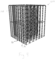
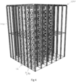
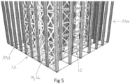
- Figs. 4 and 5 show a framework structure 100 comprising a plurality of upright members 102.
- Figs 4 and 5 further illustrate framework structure 100 with a modular plate system 12 comprising a plurality of plate members 14 installed between adjacent upright members 102.
- the plate members 14 are bracing plate members 16.
- the term "bracing plate” as used herein means a plate member with a shape and configuration, and made of a material, specifically intended to provide structural stability to the framework, whereby a plurality of such bracing plates can provide sufficient stability that the framework does not need to be censured to an external structure.
- a sufficient number and placement of bracing members is installed in order to provide structural stability for the framework structure.
- the bracing plate members may be installed along an outside row of upright members 102, or may be installed between upright members located in the interior of the framework structure.
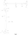
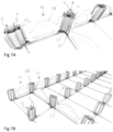
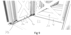
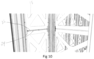
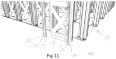
- FIGs 6 -13 illustrate bracing plate members 16 and the manner in which the plate members 14 in general are installed between upright members 102.
- a plate member in this instance a bracing plate member 16
- a plate segment 18 connected intermediate two retaining profiles 20.
- Fig 11 shows the assembly of the plate segment to the retaining profiles in exploded view.
- retaining profiles 20 have a flange 21 to which plate segments 18 are connected, for example by bolts 30.
- plate segment 18, in the case of a bracing plate member 16 is a plate with preferably four essentially triangular cutouts 22 to form an X shaped pattern, although any shape that provides structural stability can be employed. Other examples of such shapes may be a plate with a plurality of circular cut outs, a plate in the shape of triangular struts, or a solid plate, however a plate with cutouts is preferred. Such cutouts reduce the weight of the plate segment, while the shape of the plate is designed to provide stability. For example the illustrated X shape is shown to provide excellent structural stability.
- the material of the plate segment 18 in the case of a bracing plate member 16 is preferably metal, most preferably aluminum. In the case where the plate member is a functional plate member, the plate segment 18 will be made of a material appropriate to the desired function. For example, a fire resistant plate member, and insulated plate member etc.
- Retaining profiles 20 are preferably extruded aluminum profiles having a length equal to all of, or at least part of the length of the sides of the plate segment 18.
- Retaining profiles 20 have a cross sectional shape adapted specifically to fit between two adjacent container guiding plates 9 of corner sections 8, as shown in Figs 7A, 7B and 8 .
- upright members 102 are extruded aluminum profiles having a box shape that fits securely and essentially occupies the space between corner guiding plates 9, with corner guiding plates 9 being relatively thin extruded aluminum having a degree of flexibility whereby they may be slightly spread apart to permit insertion of retaining profiles 20.
- guiding plate 9 have an inwardly projecting rib 24.
- Retailing profiles 20 have two corresponding grooves 25 arranged to receive inwardly projecting ribs 24, thereby laterally securing the plate member between two upright members, for example in a snap fit manner. It should be understood that other sets of reciprocal shapes for the container guiding plates 9 and retaining profiles 20 could be employed that provide a secure engagement, provided that the retaining profiles 20 may easily attach to the upright members between adjacent container guiding plates.
- plate segment 18 at least in the embodiment where the plate member is a bracing plate member 16, comprises a lower flange 26.
- Lower flange 26 is equipped with a plurality of bolt holes 28, through which bolts 30 may be used to secure the bracing plate member to a floor 32 upon which the framework structure rests.
- Other attachment means could also be employed.
- the plate members may in some uses have a function other than or in addition to providing stability to the framework structure. Plate members with such additional or different function are herein referred to as "functional" plate members. In some embodiments it may not be necessary to bolt the functional plate members to the floor or to the framework structure.
- the plate system is installed by attaching two retaining profiles 20 to two adjacent upright members 102 at the lowest level of the framework structure.
- the retaining profiles 20 are connected to upright members 102 by inserting the retaining profiles between guide plates 9, which is possible due to the relative flexibility of guide plates 9.
- guide plates 9 have ribs that snap into corresponding grooves in the retaining profiles.
- a plate segment is then connected to the retaining profiles 20 by bolts 30 through predrilled alignment holes in flange 21.
- the preinstallation of the retaining profiles, together with flange 21, provides easy access to attach the plate segment.
- the plate segment is then bolted to the floor through predrilled holes in a lower flange part 26.
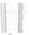
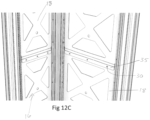
- FIG. 12A illustrates alternate embodiments for connecting the vertically adjacent plate members.
- plate segments 18 in one embodiment are equipped with a lower flange 26 and an upper flange 34 that project at about 90 degrees. Vertically adjacent plate segments can thus be bolted together as shown in Figs 10 and 12 through predrilled, alignment holes.
- plate segment 18 has an offset lip 35 arranged to overlap the adjacent plate segment 18.
- a rail interface plate 36 is provided as shown in Fig 13A and B .
- Rail interface plate 36 has an offset upper portion 38 arranged to engage with and be connected to rail system 108 and a lower part 37 arranged to overlap the uppermost plate member 16.
- Self boring screws 40 are used to secure the lower part 37 of interface plate 36 to the uppermost plate member 16 rather than employing predrilled holes, since misalignment or height differences would often prevent the upper holes from aligning properly.
- the self boring screws allow any height difference or other misalignment of the framework structure to be accounted for by the interface plates.
- the plate members 14 have a function which does not have to provide stabilization, it may not be necessary to secure the modular plate system 12 to the rail system 108.
- the present invention provides a method for stabilizing the framework structure of an automated storage and retrieval system.
- a plurality of bracing plate members 16 are installed, comprising plate segments 18 attached between two retaining profiles 20.
- Retaining profiles 20 are inserted between guide plates 9 of adjacent upright members 102 of an assembled framework structure 100 and plate segment 18 bolted to the retaining profiles.
- the lowermost bracing plate member is attached to floor 32 of the framework structure, and vertically adjacent bracing plate members are bolted together as shown in figs 12A-C .
- rail interface plates 36 connect the plate system to rail system 108 with rail interface plates 36 and self boring screws 40 used to compensate for any misalignment of the framework structure.
- Fig 14 illustrates an embodiment of the modular plate system 12 where the plate members 14 are functional plate members 42, defined as plate members having a function other than or in addition to a stabilizing function.
- the functional plate members 42 may be insulated plates having the function of creating a refrigerated zone in the storage and retrieval system.
- the functional plate members 42 may also be fire retardant plates having the function of creating a fire barrier.
- the plate segment 18 is made of or comprises a material appropriate for the given function, and attached between retaining profiles 20 as described above.
- the invention therefore provides a method of creating a functional zone 44 in a storage and retrieval system, by providing a plurality of functional plate segments 18 to form, together with retaining profiles 20, a plurality of functional plate members 42.
- the functional plate members 42 may be retrofitted to an existing storage structure, for example, in order to provide some new functionality or to reconfigure some previously installed functionality.
- a sufficient number of functional plate members 42 are installed between upright members 102 as described above in order to form the desired size and shape of the functional zone 44.
- Functional zone 44 may be, for example, an insulated zone, a refrigerated zone, a fire barrier or zone, a sound proof zone or any zone that may be defined by the functional nature of the plate members.
- the functional plate members may not always perform a stabilizing function it may not be necessary to bolt the functional plate members 42 together and/or to the framework structure or floor as described above in all situations, although it should be understood that the functional plate members could also simultaneously have a stabilizing function, in which case bolting would be preferred. Because the functional plate members may be easily inserted into place, functional zones may be created, removed, resized and repurposed at will even in an operational storage system by programming the storage vehicles to avoid the area being created, resized or repurposed.
Landscapes
- Engineering & Computer Science (AREA)
- Mechanical Engineering (AREA)
- Physics & Mathematics (AREA)
- Chemical & Material Sciences (AREA)
- Combustion & Propulsion (AREA)
- Transportation (AREA)
- Mathematical Physics (AREA)
- Thermal Sciences (AREA)
- Health & Medical Sciences (AREA)
- Public Health (AREA)
- Business, Economics & Management (AREA)
- Emergency Management (AREA)
- Operations Research (AREA)
- Warehouses Or Storage Devices (AREA)
- Refrigerator Housings (AREA)
Applications Claiming Priority (3)
| Application Number | Priority Date | Filing Date | Title |
|---|---|---|---|
| NO20200118A NO348898B1 (en) | 2020-01-31 | 2020-01-31 | Automated storage system with framework mounted modular plate system and bracing arrangement and method of stabilizing a framework structure |
| PCT/EP2021/052301 WO2021152170A1 (fr) | 2020-01-31 | 2021-02-01 | Système de stockage automatisé à système de plaques modulaires monté sur ossature et agencement de renforcement |
| EP21703007.1A EP4097032A1 (fr) | 2020-01-31 | 2021-02-01 | Système de stockage automatisé à système de plaques modulaires monté sur ossature et agencement de renforcement |
Related Parent Applications (1)
| Application Number | Title | Priority Date | Filing Date |
|---|---|---|---|
| EP21703007.1A Division EP4097032A1 (fr) | 2020-01-31 | 2021-02-01 | Système de stockage automatisé à système de plaques modulaires monté sur ossature et agencement de renforcement |
Publications (2)
| Publication Number | Publication Date |
|---|---|
| EP4545384A2 true EP4545384A2 (fr) | 2025-04-30 |
| EP4545384A3 EP4545384A3 (fr) | 2025-07-09 |
Family
ID=74505272
Family Applications (2)
| Application Number | Title | Priority Date | Filing Date |
|---|---|---|---|
| EP21703007.1A Pending EP4097032A1 (fr) | 2020-01-31 | 2021-02-01 | Système de stockage automatisé à système de plaques modulaires monté sur ossature et agencement de renforcement |
| EP24223662.8A Pending EP4545384A3 (fr) | 2020-01-31 | 2021-02-01 | Système de stockage automatisé avec système de plaque modulaire monté sur un cadre et agencement de renforcement |
Family Applications Before (1)
| Application Number | Title | Priority Date | Filing Date |
|---|---|---|---|
| EP21703007.1A Pending EP4097032A1 (fr) | 2020-01-31 | 2021-02-01 | Système de stockage automatisé à système de plaques modulaires monté sur ossature et agencement de renforcement |
Country Status (8)
| Country | Link |
|---|---|
| US (2) | US12258209B2 (fr) |
| EP (2) | EP4097032A1 (fr) |
| JP (1) | JP7709446B2 (fr) |
| KR (1) | KR20220132623A (fr) |
| CN (2) | CN115038653B (fr) |
| CA (1) | CA3162384A1 (fr) |
| NO (1) | NO348898B1 (fr) |
| WO (1) | WO2021152170A1 (fr) |
Families Citing this family (7)
| Publication number | Priority date | Publication date | Assignee | Title |
|---|---|---|---|---|
| GB202003056D0 (en) * | 2020-03-03 | 2020-04-15 | Ocado Innovation Ltd | A grid frame work structure |
| GB202003047D0 (en) * | 2020-03-03 | 2020-04-15 | Ocado Innovation Ltd | A grid framework structure |
| EP4196418A1 (fr) * | 2020-08-14 | 2023-06-21 | Ocado Innovation Limited | Structure d'ossature de grille |
| GB202016081D0 (en) | 2020-08-14 | 2020-11-25 | Ocado Innovation Ltd | Track assembly for a storage system |
| NO347235B1 (en) * | 2022-01-07 | 2023-07-24 | Autostore Tech As | Variable temperature zone in a storage and retrieval system |
| DE102022202779B3 (de) | 2022-03-22 | 2023-05-04 | Gebhardt Fördertechnik GmbH | Lager- und Entnahmesystem sowie Wand für ein Lager- und Entnahmesystem |
| AU2024343917A1 (en) * | 2023-09-22 | 2026-02-26 | Autostore Technology AS | Column spacer for mounting between two adjacent upright members of a framework structure of an automated storage and retrieval system |
Citations (8)
| Publication number | Priority date | Publication date | Assignee | Title |
|---|---|---|---|---|
| NO317366B1 (no) | 1999-07-01 | 2004-10-18 | Autostore As | Lagringsanlegg med fjernstyrte vogner med to hjulsett og heisinnretning for drift på skinner anlagt i kryss over kolonner av lagringsenheter som er adskilt med vertikale profilstolper |
| WO2014075937A1 (fr) | 2012-11-13 | 2014-05-22 | Jakob Hatteland Logistics As | Système de stockage |
| WO2014090684A1 (fr) | 2012-12-10 | 2014-06-19 | Jakob Hatteland Logistics As | Robot pour le transport de bacs de stockage |
| WO2015193278A1 (fr) | 2014-06-19 | 2015-12-23 | Jakob Hatteland Logistics As | Robot pour transporter des bacs de stockage |
| WO2016172793A1 (fr) | 2015-04-27 | 2016-11-03 | Attabotics Inc. | Système de stockage et de récupération |
| WO2018146304A1 (fr) | 2017-02-13 | 2018-08-16 | Autostore Technology AS | Agencement de rails destiné à un système de stockage |
| WO2019010367A1 (fr) | 2017-07-07 | 2019-01-10 | The Procter & Gamble Company | Compositions de nettoyage comprenant des esteramines alcoxylées |
| WO2019101367A1 (fr) | 2017-11-22 | 2019-05-31 | Autostore Technology AS | Système de stockage |
Family Cites Families (32)
| Publication number | Priority date | Publication date | Assignee | Title |
|---|---|---|---|---|
| US5219406A (en) * | 1991-12-23 | 1993-06-15 | Schwartz Bros. Wood & Metal Furnitures Ltd. | Versatile modular office partitions |
| US6298612B1 (en) * | 1995-09-05 | 2001-10-09 | James A. Adams | Wall strengthening component |
| DE19949926C1 (de) * | 1999-10-16 | 2001-05-10 | Christof Kaiser | Leitungssystem |
| TW521801U (en) * | 2001-08-23 | 2003-02-21 | Yu-An Liu | Jointing device for partitioning system |
| US20030213208A1 (en) | 2002-05-15 | 2003-11-20 | Ghislain Belanger | Composite building stud |
| JP2006328870A (ja) | 2005-05-27 | 2006-12-07 | Itoki Corp | 間仕切壁の支柱変形防止装置 |
| JP4332148B2 (ja) | 2005-11-11 | 2009-09-16 | 株式会社内田洋行 | 空間構造体 |
| KR101341315B1 (ko) * | 2005-11-11 | 2013-12-12 | 가부시기가이샤 우찌다요우고우 | 평판 고정 장치 |
| US7828161B2 (en) * | 2007-10-24 | 2010-11-09 | Konstant Products, Inc. | Bases for storage rack trusses |
| WO2011066648A1 (fr) * | 2009-12-02 | 2011-06-09 | The Econo-Rack Group Inc. | Montant de renfort pour palettier, et palettier le comprenant |
| CN102884358B (zh) * | 2010-04-23 | 2015-08-26 | 普帝龙集成房屋技术(重庆)有限公司 | 快速连接结构系统 |
| US9004715B1 (en) * | 2010-09-10 | 2015-04-14 | Emergency Technology, Inc. | Modular structural frame lighting |
| CN202000724U (zh) * | 2011-03-17 | 2011-10-05 | 罗煜 | 灯箱支撑柱 |
| WO2014042502A1 (fr) * | 2012-09-17 | 2014-03-20 | Eleven Solutions Rfe S.A. De C.V. | Système de construction modulaire de coffrage permanent à perforations multiples pour béton ou béton armé |
| US10016076B2 (en) * | 2013-05-02 | 2018-07-10 | Environmental Compliance Solutions, Llc | Battery spill containment system and method of making the same |
| CN203769063U (zh) * | 2014-03-18 | 2014-08-13 | 北京光景照明设计有限公司 | 框架结构单元与结构框架 |
| CN203769061U (zh) * | 2014-03-18 | 2014-08-13 | 北京光景照明设计有限公司 | 梁柱结构建筑物 |
| CN203769059U (zh) * | 2014-03-18 | 2014-08-13 | 北京光景照明设计有限公司 | 框架结构建筑物 |
| US20160369941A1 (en) * | 2015-06-20 | 2016-12-22 | Robert Consaul | Bolt-on adaptable bracket assembly for pallet racks to prevent wall damage and flue space violations |
| CN205179583U (zh) * | 2015-11-25 | 2016-04-20 | 艾普斯(天津)工业组装技术有限公司 | 布线系统拼装安装板 |
| NO20160118A1 (en) * | 2016-01-26 | 2017-07-27 | Autostore Tech As | Remotely operated vehicle |
| CN205944733U (zh) * | 2016-05-25 | 2017-02-08 | 沈阳天通电力设备有限公司 | 开关柜框架结构 |
| CN108217033A (zh) * | 2016-12-15 | 2018-06-29 | 詹志光 | 一种易拆装的环保铝合金烟叶货架 |
| US10314395B2 (en) * | 2017-02-21 | 2019-06-11 | James E. McGhee, III | Pallet spacer system and method of use |
| GB201707922D0 (en) * | 2017-05-17 | 2017-06-28 | Ocado Innovation Ltd | Modular storage systems and methods |
| WO2019094511A1 (fr) * | 2017-11-07 | 2019-05-16 | Nordstrom, Inc. | Systèmes et procédés de stockage, de récupération et de tri dans une chaîne logistique |
| CN208502331U (zh) | 2018-06-04 | 2019-02-15 | 中山莱博顿卫浴有限公司 | 一种淋浴套装不锈钢型材铝型横材结构 |
| CN209760443U (zh) * | 2019-01-04 | 2019-12-10 | 深圳市坐标建筑装饰工程股份有限公司 | 一种快速拼接件及其拼接框架结构 |
| GB201900653D0 (en) * | 2019-01-17 | 2019-03-06 | Ocado Innovation Ltd | RFID tags |
| CN109629712B (zh) * | 2019-02-01 | 2024-03-15 | 浙江绿尚建材有限公司 | 拼接式型材组件及其拼接产品 |
| US10908601B2 (en) * | 2019-04-10 | 2021-02-02 | Fetch Robotics, Inc. | Robotic cart configured for effective navigation and multi-orientation docking |
| CA3099016A1 (en) * | 2019-11-13 | 2021-05-13 | Pipp Mobile Storage Systems, Inc. | Mobile storage system with elevated platform |
-
2020
- 2020-01-31 NO NO20200118A patent/NO348898B1/en unknown
-
2021
- 2021-02-01 EP EP21703007.1A patent/EP4097032A1/fr active Pending
- 2021-02-01 EP EP24223662.8A patent/EP4545384A3/fr active Pending
- 2021-02-01 CN CN202180011110.6A patent/CN115038653B/zh active Active
- 2021-02-01 WO PCT/EP2021/052301 patent/WO2021152170A1/fr not_active Ceased
- 2021-02-01 KR KR1020227029698A patent/KR20220132623A/ko active Pending
- 2021-02-01 US US17/792,275 patent/US12258209B2/en active Active
- 2021-02-01 JP JP2022545361A patent/JP7709446B2/ja active Active
- 2021-02-01 CN CN202510212208.8A patent/CN120039534A/zh active Pending
- 2021-02-01 CA CA3162384A patent/CA3162384A1/fr active Pending
-
2025
- 2025-03-10 US US19/074,576 patent/US20250206531A1/en active Pending
Patent Citations (8)
| Publication number | Priority date | Publication date | Assignee | Title |
|---|---|---|---|---|
| NO317366B1 (no) | 1999-07-01 | 2004-10-18 | Autostore As | Lagringsanlegg med fjernstyrte vogner med to hjulsett og heisinnretning for drift på skinner anlagt i kryss over kolonner av lagringsenheter som er adskilt med vertikale profilstolper |
| WO2014075937A1 (fr) | 2012-11-13 | 2014-05-22 | Jakob Hatteland Logistics As | Système de stockage |
| WO2014090684A1 (fr) | 2012-12-10 | 2014-06-19 | Jakob Hatteland Logistics As | Robot pour le transport de bacs de stockage |
| WO2015193278A1 (fr) | 2014-06-19 | 2015-12-23 | Jakob Hatteland Logistics As | Robot pour transporter des bacs de stockage |
| WO2016172793A1 (fr) | 2015-04-27 | 2016-11-03 | Attabotics Inc. | Système de stockage et de récupération |
| WO2018146304A1 (fr) | 2017-02-13 | 2018-08-16 | Autostore Technology AS | Agencement de rails destiné à un système de stockage |
| WO2019010367A1 (fr) | 2017-07-07 | 2019-01-10 | The Procter & Gamble Company | Compositions de nettoyage comprenant des esteramines alcoxylées |
| WO2019101367A1 (fr) | 2017-11-22 | 2019-05-31 | Autostore Technology AS | Système de stockage |
Also Published As
| Publication number | Publication date |
|---|---|
| NO20200118A1 (en) | 2021-08-02 |
| CN115038653B (zh) | 2025-03-14 |
| NO348898B1 (en) | 2025-07-07 |
| US12258209B2 (en) | 2025-03-25 |
| CN115038653A (zh) | 2022-09-09 |
| KR20220132623A (ko) | 2022-09-30 |
| WO2021152170A1 (fr) | 2021-08-05 |
| US20230048613A1 (en) | 2023-02-16 |
| JP7709446B2 (ja) | 2025-07-16 |
| EP4097032A1 (fr) | 2022-12-07 |
| EP4545384A3 (fr) | 2025-07-09 |
| CN120039534A (zh) | 2025-05-27 |
| CA3162384A1 (fr) | 2021-08-05 |
| JP2023512658A (ja) | 2023-03-28 |
| US20250206531A1 (en) | 2025-06-26 |
Similar Documents
| Publication | Publication Date | Title |
|---|---|---|
| US12258209B2 (en) | Automated storage system with framework mounted modular plate system and bracing arrangement | |
| EP4126706B1 (fr) | Système de stockage automatisé doté d'une tour de stockage dans un logement isolant | |
| US12606374B2 (en) | Automated storage tower with multiple rows | |
| EP3962837A1 (fr) | Système de stockage | |
| KR102936979B1 (ko) | 복수의 적층된 컨테이너를 통해서 연장되는 유동 경로를 포함하는 자동화된 저장 및 회수 시스템 | |
| NO346551B1 (en) | A storage tower, an automated storage and retrieval system comprising a storage tower, and a method of using same | |
| US20240158165A1 (en) | An automated storage system | |
| US20240191494A1 (en) | Bracing arrangement | |
| HK40078110A (en) | Automated storage system with framework mounted modular plate system and bracing arrangement | |
| HK40078110B (zh) | 带有框架安装模块化板系统和加固装置的自动化储存系统 | |
| EP4735355A1 (fr) | Système de stockage à plusieurs niveaux | |
| NO20230973A1 (en) | Leveling foot method for spacing upright members of a framework structure | |
| HK40104142A (zh) | 自动储存系统 |
Legal Events
| Date | Code | Title | Description |
|---|---|---|---|
| PUAI | Public reference made under article 153(3) epc to a published international application that has entered the european phase |
Free format text: ORIGINAL CODE: 0009012 |
|
| STAA | Information on the status of an ep patent application or granted ep patent |
Free format text: STATUS: REQUEST FOR EXAMINATION WAS MADE |
|
| 17P | Request for examination filed |
Effective date: 20241230 |
|
| AC | Divisional application: reference to earlier application |
Ref document number: 4097032 Country of ref document: EP Kind code of ref document: P |
|
| AK | Designated contracting states |
Kind code of ref document: A2 Designated state(s): AL AT BE BG CH CY CZ DE DK EE ES FI FR GB GR HR HU IE IS IT LI LT LU LV MC MK MT NL NO PL PT RO RS SE SI SK SM TR |
|
| REG | Reference to a national code |
Ref country code: DE Ref legal event code: R079 Free format text: PREVIOUS MAIN CLASS: B62D0033020000 Ipc: B65G0001040000 |
|
| PUAL | Search report despatched |
Free format text: ORIGINAL CODE: 0009013 |
|
| AK | Designated contracting states |
Kind code of ref document: A3 Designated state(s): AL AT BE BG CH CY CZ DE DK EE ES FI FR GB GR HR HU IE IS IT LI LT LU LV MC MK MT NL NO PL PT RO RS SE SI SK SM TR |
|
| RIC1 | Information provided on ipc code assigned before grant |
Ipc: A62C 3/00 20060101ALN20250602BHEP Ipc: B62D 63/02 20060101ALI20250602BHEP Ipc: B62D 33/04 20060101ALI20250602BHEP Ipc: B62D 33/02 20060101ALI20250602BHEP Ipc: B65G 1/04 20060101AFI20250602BHEP |
|
| STAA | Information on the status of an ep patent application or granted ep patent |
Free format text: STATUS: EXAMINATION IS IN PROGRESS |
|
| RAP3 | Party data changed (applicant data changed or rights of an application transferred) |
Owner name: AUTOSTORE TECHNOLOGY AS |
|
| 17Q | First examination report despatched |
Effective date: 20260326 |