EP4545681A2 - Configurations de bord de substrat pour revêtements céramiques - Google Patents
Configurations de bord de substrat pour revêtements céramiques Download PDFInfo
- Publication number
- EP4545681A2 EP4545681A2 EP25159458.6A EP25159458A EP4545681A2 EP 4545681 A2 EP4545681 A2 EP 4545681A2 EP 25159458 A EP25159458 A EP 25159458A EP 4545681 A2 EP4545681 A2 EP 4545681A2
- Authority
- EP
- European Patent Office
- Prior art keywords
- channels
- group
- inner diameter
- along
- bevel
- Prior art date
- Legal status (The legal status is an assumption and is not a legal conclusion. Google has not performed a legal analysis and makes no representation as to the accuracy of the status listed.)
- Pending
Links
Images


Classifications
-
- F—MECHANICAL ENGINEERING; LIGHTING; HEATING; WEAPONS; BLASTING
- F01—MACHINES OR ENGINES IN GENERAL; ENGINE PLANTS IN GENERAL; STEAM ENGINES
- F01D—NON-POSITIVE DISPLACEMENT MACHINES OR ENGINES, e.g. STEAM TURBINES
- F01D11/00—Preventing or minimising internal leakage of working-fluid, e.g. between stages
- F01D11/08—Preventing or minimising internal leakage of working-fluid, e.g. between stages for sealing space between rotor blade tips and stator
- F01D11/12—Preventing or minimising internal leakage of working-fluid, e.g. between stages for sealing space between rotor blade tips and stator using a rubstrip, e.g. erodible. deformable or resiliently-biased part
- F01D11/122—Preventing or minimising internal leakage of working-fluid, e.g. between stages for sealing space between rotor blade tips and stator using a rubstrip, e.g. erodible. deformable or resiliently-biased part with erodable or abradable material
-
- B—PERFORMING OPERATIONS; TRANSPORTING
- B23—MACHINE TOOLS; METAL-WORKING NOT OTHERWISE PROVIDED FOR
- B23P—METAL-WORKING NOT OTHERWISE PROVIDED FOR; COMBINED OPERATIONS; UNIVERSAL MACHINE TOOLS
- B23P15/00—Making specific metal objects by operations not covered by a single other subclass or a group in this subclass
- B23P15/008—Rocket engine parts, e.g. nozzles, combustion chambers
-
- F—MECHANICAL ENGINEERING; LIGHTING; HEATING; WEAPONS; BLASTING
- F01—MACHINES OR ENGINES IN GENERAL; ENGINE PLANTS IN GENERAL; STEAM ENGINES
- F01D—NON-POSITIVE DISPLACEMENT MACHINES OR ENGINES, e.g. STEAM TURBINES
- F01D11/00—Preventing or minimising internal leakage of working-fluid, e.g. between stages
- F01D11/08—Preventing or minimising internal leakage of working-fluid, e.g. between stages for sealing space between rotor blade tips and stator
- F01D11/12—Preventing or minimising internal leakage of working-fluid, e.g. between stages for sealing space between rotor blade tips and stator using a rubstrip, e.g. erodible. deformable or resiliently-biased part
- F01D11/122—Preventing or minimising internal leakage of working-fluid, e.g. between stages for sealing space between rotor blade tips and stator using a rubstrip, e.g. erodible. deformable or resiliently-biased part with erodable or abradable material
- F01D11/125—Preventing or minimising internal leakage of working-fluid, e.g. between stages for sealing space between rotor blade tips and stator using a rubstrip, e.g. erodible. deformable or resiliently-biased part with erodable or abradable material with a reinforcing structure
-
- F—MECHANICAL ENGINEERING; LIGHTING; HEATING; WEAPONS; BLASTING
- F01—MACHINES OR ENGINES IN GENERAL; ENGINE PLANTS IN GENERAL; STEAM ENGINES
- F01D—NON-POSITIVE DISPLACEMENT MACHINES OR ENGINES, e.g. STEAM TURBINES
- F01D25/00—Component parts, details, or accessories, not provided for in, or of interest apart from, other groups
- F01D25/007—Preventing corrosion
-
- F—MECHANICAL ENGINEERING; LIGHTING; HEATING; WEAPONS; BLASTING
- F01—MACHINES OR ENGINES IN GENERAL; ENGINE PLANTS IN GENERAL; STEAM ENGINES
- F01D—NON-POSITIVE DISPLACEMENT MACHINES OR ENGINES, e.g. STEAM TURBINES
- F01D25/00—Component parts, details, or accessories, not provided for in, or of interest apart from, other groups
- F01D25/24—Casings; Casing parts, e.g. diaphragms, casing fastenings
- F01D25/246—Fastening of diaphragms or stator-rings
-
- F—MECHANICAL ENGINEERING; LIGHTING; HEATING; WEAPONS; BLASTING
- F01—MACHINES OR ENGINES IN GENERAL; ENGINE PLANTS IN GENERAL; STEAM ENGINES
- F01D—NON-POSITIVE DISPLACEMENT MACHINES OR ENGINES, e.g. STEAM TURBINES
- F01D5/00—Blades; Blade-carrying members; Heating, heat-insulating, cooling or antivibration means on the blades or the members
- F01D5/12—Blades
- F01D5/28—Selecting particular materials; Particular measures relating thereto; Measures against erosion or corrosion
- F01D5/288—Protective coatings for blades
-
- F—MECHANICAL ENGINEERING; LIGHTING; HEATING; WEAPONS; BLASTING
- F23—COMBUSTION APPARATUS; COMBUSTION PROCESSES
- F23R—GENERATING COMBUSTION PRODUCTS OF HIGH PRESSURE OR HIGH VELOCITY, e.g. GAS-TURBINE COMBUSTION CHAMBERS
- F23R3/00—Continuous combustion chambers using liquid or gaseous fuel
- F23R3/002—Wall structures
-
- F—MECHANICAL ENGINEERING; LIGHTING; HEATING; WEAPONS; BLASTING
- F23—COMBUSTION APPARATUS; COMBUSTION PROCESSES
- F23R—GENERATING COMBUSTION PRODUCTS OF HIGH PRESSURE OR HIGH VELOCITY, e.g. GAS-TURBINE COMBUSTION CHAMBERS
- F23R3/00—Continuous combustion chambers using liquid or gaseous fuel
- F23R3/007—Continuous combustion chambers using liquid or gaseous fuel constructed mainly of ceramic components
-
- B—PERFORMING OPERATIONS; TRANSPORTING
- B23—MACHINE TOOLS; METAL-WORKING NOT OTHERWISE PROVIDED FOR
- B23P—METAL-WORKING NOT OTHERWISE PROVIDED FOR; COMBINED OPERATIONS; UNIVERSAL MACHINE TOOLS
- B23P15/00—Making specific metal objects by operations not covered by a single other subclass or a group in this subclass
- B23P15/04—Making specific metal objects by operations not covered by a single other subclass or a group in this subclass turbine or like blades from several pieces
-
- C—CHEMISTRY; METALLURGY
- C23—COATING METALLIC MATERIAL; COATING MATERIAL WITH METALLIC MATERIAL; CHEMICAL SURFACE TREATMENT; DIFFUSION TREATMENT OF METALLIC MATERIAL; COATING BY VACUUM EVAPORATION, BY SPUTTERING, BY ION IMPLANTATION OR BY CHEMICAL VAPOUR DEPOSITION, IN GENERAL; INHIBITING CORROSION OF METALLIC MATERIAL OR INCRUSTATION IN GENERAL
- C23C—COATING METALLIC MATERIAL; COATING MATERIAL WITH METALLIC MATERIAL; SURFACE TREATMENT OF METALLIC MATERIAL BY DIFFUSION INTO THE SURFACE, BY CHEMICAL CONVERSION OR SUBSTITUTION; COATING BY VACUUM EVAPORATION, BY SPUTTERING, BY ION IMPLANTATION OR BY CHEMICAL VAPOUR DEPOSITION, IN GENERAL
- C23C4/00—Coating by spraying the coating material in the molten state, e.g. by flame, plasma or electric discharge
- C23C4/04—Coating by spraying the coating material in the molten state, e.g. by flame, plasma or electric discharge characterised by the coating material
- C23C4/06—Metallic material
- C23C4/08—Metallic material containing only metal elements
-
- F—MECHANICAL ENGINEERING; LIGHTING; HEATING; WEAPONS; BLASTING
- F05—INDEXING SCHEMES RELATING TO ENGINES OR PUMPS IN VARIOUS SUBCLASSES OF CLASSES F01-F04
- F05D—INDEXING SCHEME FOR ASPECTS RELATING TO NON-POSITIVE-DISPLACEMENT MACHINES OR ENGINES, GAS-TURBINES OR JET-PROPULSION PLANTS
- F05D2230/00—Manufacture
- F05D2230/10—Manufacture by removing material
- F05D2230/14—Micromachining
-
- F—MECHANICAL ENGINEERING; LIGHTING; HEATING; WEAPONS; BLASTING
- F05—INDEXING SCHEMES RELATING TO ENGINES OR PUMPS IN VARIOUS SUBCLASSES OF CLASSES F01-F04
- F05D—INDEXING SCHEME FOR ASPECTS RELATING TO NON-POSITIVE-DISPLACEMENT MACHINES OR ENGINES, GAS-TURBINES OR JET-PROPULSION PLANTS
- F05D2230/00—Manufacture
- F05D2230/30—Manufacture with deposition of material
- F05D2230/31—Layer deposition
- F05D2230/312—Layer deposition by plasma spraying
-
- F—MECHANICAL ENGINEERING; LIGHTING; HEATING; WEAPONS; BLASTING
- F05—INDEXING SCHEMES RELATING TO ENGINES OR PUMPS IN VARIOUS SUBCLASSES OF CLASSES F01-F04
- F05D—INDEXING SCHEME FOR ASPECTS RELATING TO NON-POSITIVE-DISPLACEMENT MACHINES OR ENGINES, GAS-TURBINES OR JET-PROPULSION PLANTS
- F05D2230/00—Manufacture
- F05D2230/30—Manufacture with deposition of material
- F05D2230/31—Layer deposition
- F05D2230/313—Layer deposition by physical vapour deposition
-
- F—MECHANICAL ENGINEERING; LIGHTING; HEATING; WEAPONS; BLASTING
- F05—INDEXING SCHEMES RELATING TO ENGINES OR PUMPS IN VARIOUS SUBCLASSES OF CLASSES F01-F04
- F05D—INDEXING SCHEME FOR ASPECTS RELATING TO NON-POSITIVE-DISPLACEMENT MACHINES OR ENGINES, GAS-TURBINES OR JET-PROPULSION PLANTS
- F05D2230/00—Manufacture
- F05D2230/90—Coating; Surface treatment
-
- F—MECHANICAL ENGINEERING; LIGHTING; HEATING; WEAPONS; BLASTING
- F05—INDEXING SCHEMES RELATING TO ENGINES OR PUMPS IN VARIOUS SUBCLASSES OF CLASSES F01-F04
- F05D—INDEXING SCHEME FOR ASPECTS RELATING TO NON-POSITIVE-DISPLACEMENT MACHINES OR ENGINES, GAS-TURBINES OR JET-PROPULSION PLANTS
- F05D2240/00—Components
- F05D2240/10—Stators
- F05D2240/11—Shroud seal segments
-
- F—MECHANICAL ENGINEERING; LIGHTING; HEATING; WEAPONS; BLASTING
- F05—INDEXING SCHEMES RELATING TO ENGINES OR PUMPS IN VARIOUS SUBCLASSES OF CLASSES F01-F04
- F05D—INDEXING SCHEME FOR ASPECTS RELATING TO NON-POSITIVE-DISPLACEMENT MACHINES OR ENGINES, GAS-TURBINES OR JET-PROPULSION PLANTS
- F05D2240/00—Components
- F05D2240/55—Seals
-
- F—MECHANICAL ENGINEERING; LIGHTING; HEATING; WEAPONS; BLASTING
- F05—INDEXING SCHEMES RELATING TO ENGINES OR PUMPS IN VARIOUS SUBCLASSES OF CLASSES F01-F04
- F05D—INDEXING SCHEME FOR ASPECTS RELATING TO NON-POSITIVE-DISPLACEMENT MACHINES OR ENGINES, GAS-TURBINES OR JET-PROPULSION PLANTS
- F05D2240/00—Components
- F05D2240/80—Platforms for stationary or moving blades
-
- F—MECHANICAL ENGINEERING; LIGHTING; HEATING; WEAPONS; BLASTING
- F05—INDEXING SCHEMES RELATING TO ENGINES OR PUMPS IN VARIOUS SUBCLASSES OF CLASSES F01-F04
- F05D—INDEXING SCHEME FOR ASPECTS RELATING TO NON-POSITIVE-DISPLACEMENT MACHINES OR ENGINES, GAS-TURBINES OR JET-PROPULSION PLANTS
- F05D2250/00—Geometry
- F05D2250/10—Two-dimensional
- F05D2250/13—Two-dimensional trapezoidal
- F05D2250/132—Two-dimensional trapezoidal hexagonal
-
- F—MECHANICAL ENGINEERING; LIGHTING; HEATING; WEAPONS; BLASTING
- F05—INDEXING SCHEMES RELATING TO ENGINES OR PUMPS IN VARIOUS SUBCLASSES OF CLASSES F01-F04
- F05D—INDEXING SCHEME FOR ASPECTS RELATING TO NON-POSITIVE-DISPLACEMENT MACHINES OR ENGINES, GAS-TURBINES OR JET-PROPULSION PLANTS
- F05D2250/00—Geometry
- F05D2250/10—Two-dimensional
- F05D2250/14—Two-dimensional elliptical
- F05D2250/141—Two-dimensional elliptical circular
-
- F—MECHANICAL ENGINEERING; LIGHTING; HEATING; WEAPONS; BLASTING
- F05—INDEXING SCHEMES RELATING TO ENGINES OR PUMPS IN VARIOUS SUBCLASSES OF CLASSES F01-F04
- F05D—INDEXING SCHEME FOR ASPECTS RELATING TO NON-POSITIVE-DISPLACEMENT MACHINES OR ENGINES, GAS-TURBINES OR JET-PROPULSION PLANTS
- F05D2250/00—Geometry
- F05D2250/10—Two-dimensional
- F05D2250/19—Two-dimensional machined; miscellaneous
- F05D2250/191—Two-dimensional machined; miscellaneous perforated
-
- F—MECHANICAL ENGINEERING; LIGHTING; HEATING; WEAPONS; BLASTING
- F05—INDEXING SCHEMES RELATING TO ENGINES OR PUMPS IN VARIOUS SUBCLASSES OF CLASSES F01-F04
- F05D—INDEXING SCHEME FOR ASPECTS RELATING TO NON-POSITIVE-DISPLACEMENT MACHINES OR ENGINES, GAS-TURBINES OR JET-PROPULSION PLANTS
- F05D2250/00—Geometry
- F05D2250/10—Two-dimensional
- F05D2250/19—Two-dimensional machined; miscellaneous
- F05D2250/192—Two-dimensional machined; miscellaneous bevelled
-
- F—MECHANICAL ENGINEERING; LIGHTING; HEATING; WEAPONS; BLASTING
- F05—INDEXING SCHEMES RELATING TO ENGINES OR PUMPS IN VARIOUS SUBCLASSES OF CLASSES F01-F04
- F05D—INDEXING SCHEME FOR ASPECTS RELATING TO NON-POSITIVE-DISPLACEMENT MACHINES OR ENGINES, GAS-TURBINES OR JET-PROPULSION PLANTS
- F05D2250/00—Geometry
- F05D2250/10—Two-dimensional
- F05D2250/19—Two-dimensional machined; miscellaneous
- F05D2250/193—Two-dimensional machined; miscellaneous milled
-
- F—MECHANICAL ENGINEERING; LIGHTING; HEATING; WEAPONS; BLASTING
- F05—INDEXING SCHEMES RELATING TO ENGINES OR PUMPS IN VARIOUS SUBCLASSES OF CLASSES F01-F04
- F05D—INDEXING SCHEME FOR ASPECTS RELATING TO NON-POSITIVE-DISPLACEMENT MACHINES OR ENGINES, GAS-TURBINES OR JET-PROPULSION PLANTS
- F05D2250/00—Geometry
- F05D2250/20—Three-dimensional
- F05D2250/23—Three-dimensional prismatic
- F05D2250/231—Three-dimensional prismatic cylindrical
-
- F—MECHANICAL ENGINEERING; LIGHTING; HEATING; WEAPONS; BLASTING
- F05—INDEXING SCHEMES RELATING TO ENGINES OR PUMPS IN VARIOUS SUBCLASSES OF CLASSES F01-F04
- F05D—INDEXING SCHEME FOR ASPECTS RELATING TO NON-POSITIVE-DISPLACEMENT MACHINES OR ENGINES, GAS-TURBINES OR JET-PROPULSION PLANTS
- F05D2250/00—Geometry
- F05D2250/20—Three-dimensional
- F05D2250/28—Three-dimensional patterned
- F05D2250/283—Three-dimensional patterned honeycomb
-
- F—MECHANICAL ENGINEERING; LIGHTING; HEATING; WEAPONS; BLASTING
- F05—INDEXING SCHEMES RELATING TO ENGINES OR PUMPS IN VARIOUS SUBCLASSES OF CLASSES F01-F04
- F05D—INDEXING SCHEME FOR ASPECTS RELATING TO NON-POSITIVE-DISPLACEMENT MACHINES OR ENGINES, GAS-TURBINES OR JET-PROPULSION PLANTS
- F05D2250/00—Geometry
- F05D2250/20—Three-dimensional
- F05D2250/29—Three-dimensional machined; miscellaneous
- F05D2250/291—Three-dimensional machined; miscellaneous hollowed
-
- F—MECHANICAL ENGINEERING; LIGHTING; HEATING; WEAPONS; BLASTING
- F05—INDEXING SCHEMES RELATING TO ENGINES OR PUMPS IN VARIOUS SUBCLASSES OF CLASSES F01-F04
- F05D—INDEXING SCHEME FOR ASPECTS RELATING TO NON-POSITIVE-DISPLACEMENT MACHINES OR ENGINES, GAS-TURBINES OR JET-PROPULSION PLANTS
- F05D2260/00—Function
- F05D2260/95—Preventing corrosion
-
- F—MECHANICAL ENGINEERING; LIGHTING; HEATING; WEAPONS; BLASTING
- F05—INDEXING SCHEMES RELATING TO ENGINES OR PUMPS IN VARIOUS SUBCLASSES OF CLASSES F01-F04
- F05D—INDEXING SCHEME FOR ASPECTS RELATING TO NON-POSITIVE-DISPLACEMENT MACHINES OR ENGINES, GAS-TURBINES OR JET-PROPULSION PLANTS
- F05D2300/00—Materials; Properties thereof
- F05D2300/10—Metals, alloys or intermetallic compounds
- F05D2300/14—Noble metals, i.e. Ag, Au, platinum group metals
- F05D2300/143—Platinum group metals, i.e. Os, Ir, Pt, Ru, Rh, Pd
-
- F—MECHANICAL ENGINEERING; LIGHTING; HEATING; WEAPONS; BLASTING
- F05—INDEXING SCHEMES RELATING TO ENGINES OR PUMPS IN VARIOUS SUBCLASSES OF CLASSES F01-F04
- F05D—INDEXING SCHEME FOR ASPECTS RELATING TO NON-POSITIVE-DISPLACEMENT MACHINES OR ENGINES, GAS-TURBINES OR JET-PROPULSION PLANTS
- F05D2300/00—Materials; Properties thereof
- F05D2300/10—Metals, alloys or intermetallic compounds
- F05D2300/17—Alloys
- F05D2300/173—Aluminium alloys, e.g. AlCuMgPb
-
- F—MECHANICAL ENGINEERING; LIGHTING; HEATING; WEAPONS; BLASTING
- F05—INDEXING SCHEMES RELATING TO ENGINES OR PUMPS IN VARIOUS SUBCLASSES OF CLASSES F01-F04
- F05D—INDEXING SCHEME FOR ASPECTS RELATING TO NON-POSITIVE-DISPLACEMENT MACHINES OR ENGINES, GAS-TURBINES OR JET-PROPULSION PLANTS
- F05D2300/00—Materials; Properties thereof
- F05D2300/10—Metals, alloys or intermetallic compounds
- F05D2300/18—Intermetallic compounds
- F05D2300/182—Metal-aluminide intermetallic compounds
-
- F—MECHANICAL ENGINEERING; LIGHTING; HEATING; WEAPONS; BLASTING
- F05—INDEXING SCHEMES RELATING TO ENGINES OR PUMPS IN VARIOUS SUBCLASSES OF CLASSES F01-F04
- F05D—INDEXING SCHEME FOR ASPECTS RELATING TO NON-POSITIVE-DISPLACEMENT MACHINES OR ENGINES, GAS-TURBINES OR JET-PROPULSION PLANTS
- F05D2300/00—Materials; Properties thereof
- F05D2300/20—Oxide or non-oxide ceramics
- F05D2300/21—Oxide ceramics
- F05D2300/2118—Zirconium oxides
-
- F—MECHANICAL ENGINEERING; LIGHTING; HEATING; WEAPONS; BLASTING
- F05—INDEXING SCHEMES RELATING TO ENGINES OR PUMPS IN VARIOUS SUBCLASSES OF CLASSES F01-F04
- F05D—INDEXING SCHEME FOR ASPECTS RELATING TO NON-POSITIVE-DISPLACEMENT MACHINES OR ENGINES, GAS-TURBINES OR JET-PROPULSION PLANTS
- F05D2300/00—Materials; Properties thereof
- F05D2300/20—Oxide or non-oxide ceramics
- F05D2300/22—Non-oxide ceramics
- F05D2300/228—Nitrides
- F05D2300/2285—Nitrides of zirconium
-
- F—MECHANICAL ENGINEERING; LIGHTING; HEATING; WEAPONS; BLASTING
- F05—INDEXING SCHEMES RELATING TO ENGINES OR PUMPS IN VARIOUS SUBCLASSES OF CLASSES F01-F04
- F05D—INDEXING SCHEME FOR ASPECTS RELATING TO NON-POSITIVE-DISPLACEMENT MACHINES OR ENGINES, GAS-TURBINES OR JET-PROPULSION PLANTS
- F05D2300/00—Materials; Properties thereof
- F05D2300/50—Intrinsic material properties or characteristics
- F05D2300/502—Thermal properties
- F05D2300/5024—Heat conductivity
-
- F—MECHANICAL ENGINEERING; LIGHTING; HEATING; WEAPONS; BLASTING
- F05—INDEXING SCHEMES RELATING TO ENGINES OR PUMPS IN VARIOUS SUBCLASSES OF CLASSES F01-F04
- F05D—INDEXING SCHEME FOR ASPECTS RELATING TO NON-POSITIVE-DISPLACEMENT MACHINES OR ENGINES, GAS-TURBINES OR JET-PROPULSION PLANTS
- F05D2300/00—Materials; Properties thereof
- F05D2300/60—Properties or characteristics given to material by treatment or manufacturing
- F05D2300/603—Composites; e.g. fibre-reinforced
- F05D2300/6033—Ceramic matrix composites [CMC]
-
- F—MECHANICAL ENGINEERING; LIGHTING; HEATING; WEAPONS; BLASTING
- F05—INDEXING SCHEMES RELATING TO ENGINES OR PUMPS IN VARIOUS SUBCLASSES OF CLASSES F01-F04
- F05D—INDEXING SCHEME FOR ASPECTS RELATING TO NON-POSITIVE-DISPLACEMENT MACHINES OR ENGINES, GAS-TURBINES OR JET-PROPULSION PLANTS
- F05D2300/00—Materials; Properties thereof
- F05D2300/60—Properties or characteristics given to material by treatment or manufacturing
- F05D2300/611—Coating
-
- F—MECHANICAL ENGINEERING; LIGHTING; HEATING; WEAPONS; BLASTING
- F23—COMBUSTION APPARATUS; COMBUSTION PROCESSES
- F23R—GENERATING COMBUSTION PRODUCTS OF HIGH PRESSURE OR HIGH VELOCITY, e.g. GAS-TURBINE COMBUSTION CHAMBERS
- F23R2900/00—Special features of, or arrangements for continuous combustion chambers; Combustion processes therefor
- F23R2900/03044—Impingement cooled combustion chamber walls or subassemblies
-
- Y—GENERAL TAGGING OF NEW TECHNOLOGICAL DEVELOPMENTS; GENERAL TAGGING OF CROSS-SECTIONAL TECHNOLOGIES SPANNING OVER SEVERAL SECTIONS OF THE IPC; TECHNICAL SUBJECTS COVERED BY FORMER USPC CROSS-REFERENCE ART COLLECTIONS [XRACs] AND DIGESTS
- Y02—TECHNOLOGIES OR APPLICATIONS FOR MITIGATION OR ADAPTATION AGAINST CLIMATE CHANGE
- Y02T—CLIMATE CHANGE MITIGATION TECHNOLOGIES RELATED TO TRANSPORTATION
- Y02T50/00—Aeronautics or air transport
- Y02T50/60—Efficient propulsion technologies, e.g. for aircraft
-
- Y—GENERAL TAGGING OF NEW TECHNOLOGICAL DEVELOPMENTS; GENERAL TAGGING OF CROSS-SECTIONAL TECHNOLOGIES SPANNING OVER SEVERAL SECTIONS OF THE IPC; TECHNICAL SUBJECTS COVERED BY FORMER USPC CROSS-REFERENCE ART COLLECTIONS [XRACs] AND DIGESTS
- Y10—TECHNICAL SUBJECTS COVERED BY FORMER USPC
- Y10T—TECHNICAL SUBJECTS COVERED BY FORMER US CLASSIFICATION
- Y10T29/00—Metal working
- Y10T29/49—Method of mechanical manufacture
- Y10T29/49316—Impeller making
- Y10T29/4932—Turbomachine making
Definitions
- Ceramic coatings are used for several purposes in modern gas turbine engines (broadly inclusive of turbofans, turbojets, turboprops, turboshafts, and industrial gas turbines). Key purposes include being barrier coatings (environmental (EBC) and/or thermal (TBC)) and abradable coatings (e.g., in sliding engagement with an abrading member). Exemplary abradable coatings are used on the gaspath-facing inner diameter (ID) surface of blade outer air seals (BOAS) in circumferential sliding engagement with blade tips (e.g., airfoil tips or tip shrouds).
- barrier coatings environmentmental (EBC) and/or thermal (TBC)
- abradable coatings e.g., in sliding engagement with an abrading member.
- Exemplary abradable coatings are used on the gaspath-facing inner diameter (ID) surface of blade outer air seals (BOAS) in circumferential sliding engagement with blade tips (e.g., airfoil tips or tip shrouds).
- abradable coatings include rotor-to-stator interactions other than at blade tips.
- One example involves sealing between an inter-blade stage area of a rotor and inner diameter (ID) tips of stator airfoils or inner diameter sealing surfaces of ID shrouds of vanes.
- ID inner diameter
- CMAS attack reduces the ability of the coating to accommodate differential thermal expansion.
- One aspect of the disclosure involves an article comprising a body having a first face and a first bevel surface extending from the first face.
- a plurality of first channels are along the first bevel surface extending from the first face.
- a ceramic coating is along the first face and the first bevel surface.
- a further embodiment of the foregoing embodiment may additionally include the article being a gas turbine engine component.
- a further embodiment of any of the foregoing embodiments may additionally and/or alternatively include the ceramic coating comprising a stabilized zirconia.
- a further embodiment of any of the foregoing embodiments may additionally and/or alternatively include the body being metallic.
- a further embodiment of any of the foregoing embodiments may additionally and/or alternatively include the body comprising a metallic substrate and a metallic bondcoat.
- a further embodiment of any of the foregoing embodiments may additionally and/or alternatively include the metallic substrate being a nickel-based superalloy and the ceramic coating comprising a stabilized zirconia.
- a further embodiment of any of the foregoing embodiments may additionally and/or alternatively include the body having a plurality of first recesses in a pattern along the first face.
- the first channels comprise a first group of channels and a second group of channels.
- the channels of the first group are of different size than the channels of the second group.
- the channels of the first group are of different registry with the pattern than are the channels of the second group.
- a further embodiment of any of the foregoing embodiments may additionally and/or alternatively include the pattern being a hexagonal array and the hexagonal array having a first row along the first bevel surface.
- the channels of the first group are longer than the channels of the second group.
- the channels of the first group are in-phase with the recesses of the first row.
- the channels of the second group are out-of-phase with the recesses of the first row.
- a further embodiment of any of the foregoing embodiments may additionally and/or alternatively include the article being a blade outer airseal wherein: the first face is a transversely concave inner diameter surface.
- the body comprises: a first circumferential end; a second circumferential end; a first axial end; a second axial end.
- Said first bevel is between the first circumferential end and the inner diameter surface.
- a second bevel is between the second circumferential end and the inner diameter surface.
- Said plurality of first channels along the first bevel extend from the inner diameter surface to the first circumferential end.
- a plurality of second channels along the second bevel extend from the inner diameter surface to the second circumferential end.
- Said ceramic coating is along the inner diameter surface, the first bevel surface, and the second bevel surface.
- a further embodiment of any of the foregoing embodiments may additionally and/or alternatively include the body having a plurality of first recesses along the inner diameter surface.
- a further embodiment of any of the foregoing embodiments may additionally and/or alternatively include the ceramic having a by weight majority of at least one of YSZ and GSZ.
- a further embodiment of any of the foregoing embodiments may additionally and/or alternatively include the gas turbine engine further comprising a blade stage encircled by the circumferential array.
- a further embodiment of any of the foregoing embodiments may additionally and/or alternatively include the gas turbine engine having a gaspath.
- the first bevel is at an upstream end of the body along the gaspath.
- a further embodiment of any of the foregoing embodiments may additionally and/or alternatively include the first bevel being at first circumferential end of the body.
- the body has a second circumferential end and a second bevel extending from the first face to the second circumferential end.
- a further embodiment of any of the foregoing embodiments may additionally and/or alternatively include a method for manufacturing the article.
- the method comprises machining the first channels in the body and applying the coating.
- a further embodiment of any of the foregoing embodiments may additionally and/or alternatively include grinding the coating to remove artifacts of the first channels.
- a further embodiment of any of the foregoing embodiments may additionally and/or alternatively include machining each of the first channels by: plunging a rotating bit into the first surface; and drawing the rotating bit down the bevel surface.
- a further embodiment of any of the foregoing embodiments may additionally and/or alternatively include the machining each of the first channels further comprising, between the plunging and the drawing, turning the bit transverse to its rotation.
- a blade outer airseal comprising a body having: a transversely concave inner diameter surface; a first circumferential end; a second circumferential end; a first axial end; a second axial end; a first bevel between the first circumferential end and the inner diameter surface; a second bevel between the second circumferential end and the inner diameter surface.
- a plurality of first recesses are along the inner diameter surface.
- a plurality of first channels are along the first bevel extend from the inner diameter surface to the first circumferential end.
- a plurality of second channels along the second bevel extend from the inner diameter surface to the second circumferential end.
- a ceramic coating is along the inner diameter surface, the first bevel surface, and the second bevel surface.
- BOAS inter-segment edges are an area of high temperature and resultant high coating spallation due to several factors: the edges are free and exposed to heat on two sides; blade passage causes disruption of film cooling; pressure fluctuations associated with blade passage may cause hot gasses to pump in and out of intersegment gaps; and the 90° edge creates stress concentration.
- Various implementations disclosed below may addresses one or more of heat transfer, tolerance to thermally induced sintering shrinkage and the stress concentrations.
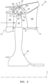
- FIG. 1 schematically illustrates an example gas turbine engine 20 that includes a fan section 22, a compressor section 24, a combustor section 26, and a turbine section 28.
- Alternative engines might include an augmenter section (not shown) among other systems or features.
- the fan section 22 drives air along a bypass flow path B while the compressor section 24 draws air in along a core flow path C where air is compressed and communicated to the combustor section 26.
- air is mixed with fuel and ignited to generate a high pressure exhaust gas stream that expands through the turbine section 28 where energy is extracted and utilized to drive the fan section 22 and the compressor section 24.
- turbofan gas turbine engine depicts a turbofan gas turbine engine
- the concepts described herein are not limited to use with turbofans as the teachings may be applied to other types of turbine engines such as turbojets, turboprops, turboshafts, and industrial gas turbines (IGT).
- IGT industrial gas turbines
- the example engine 20 generally includes a low speed spool 30 and a high speed spool 32 mounted for rotation about an engine central longitudinal axis A relative to an engine static structure 36 via several bearing systems 38. It should be understood that various bearing systems 38 at various locations may alternatively or additionally be provided.
- the low speed spool 30 generally includes an inner shaft 40 that connects a fan 42 and a low pressure (or first) compressor section 44 to a low pressure (or first) turbine section 46.
- the example engine is a geared turbofan where the inner shaft 40 drives the fan 42 through a speed change device, such as a geared architecture 48 (e.g., epicyclic transmission), to drive the fan 42 at a lower speed than the low speed spool 30.
- the high speed spool 32 includes an outer shaft 50 that interconnects a high pressure (or second) compressor section 52 and a high pressure (or second) turbine section 54.
- the inner shaft 40 and the outer shaft 50 are concentric and rotate via the bearing systems 38 about the engine central longitudinal axis A.
- the combustion section 26 comprises a combustor 56 between the high pressure compressor 52 and the high pressure turbine 54.
- the example combustor is an annular combustor.
- Alternative combustors include can-type combustor arrays.
- the high pressure turbine 54 includes at least two stages to provide a double stage high pressure turbine 54.
- the high pressure turbine 54 includes only a single stage. As used herein, a "high pressure" compressor or turbine experiences a higher pressure than a corresponding "low pressure” compressor or turbine.
- a mid-turbine frame 58 of the engine static structure 36 is generally between the high pressure turbine 54 and the low pressure turbine 46.
- the mid-turbine frame 58 further supports bearing systems 38 in the turbine section 28 as well as setting airflow entering the low pressure turbine 46.
- the core airflow C is compressed by the low pressure compressor 44, then by the high pressure compressor 52, mixed with fuel and ignited in the combustor 56 to produce high speed exhaust gases that are then expanded through the high pressure turbine 54 and low pressure turbine 46.
- the mid-turbine frame 58 includes vanes 60, which are in the core airflow path and function as an inlet guide vane for the low pressure turbine 46. Utilizing the vane 60 of the mid-turbine frame 58 as the inlet guide vane for low pressure turbine 46 decreases the length of the low pressure turbine 46 without increasing the axial length of the mid-turbine frame 58. Reducing or eliminating the number of vanes in the low pressure turbine 46 shortens the axial length of the turbine section 28. Thus, the compactness of the gas turbine engine 20 is increased and a higher power density may be achieved.
- FIG. 2 illustrates a portion 62 of a gas turbine engine, such as the gas turbine engine 20 of FIG. 1 .
- the portion 62 represents the high pressure turbine 54.
- other portions of the gas turbine engine 20 could benefit from the teachings of this disclosure, including but not limited to, the compressor section 24, the combustor section 26, and the low pressure turbine 46.
- a rotor disk 66 (only one shown, although multiple disks could be axially disposed within the portion 62) is mounted to the outer shaft 50 and rotates as a unit with respect to the engine static structure 36.
- the portion 62 includes alternating rows of rotating blades 68 (mounted to the rotor disk 66) and vanes 70A and 70B of vane assemblies 70 that are also supported within an outer casing 69 of the engine static structure 36.
- Each blade 68 of the rotor disk 66 includes a blade tip 68T that is positioned at a radially outermost portion of the blades 68.
- the blade tip 68T extends toward a blade outer air seal (BOAS) assembly 72.
- the BOAS assembly 72 may find beneficial use in many industries including aerospace, industrial, electricity generation, naval propulsion, pumps for gas and oil transmission, aircraft propulsion, vehicle engines and stationery power plants.
- the BOAS assembly 72 is disposed in an annulus radially between the outer casing 69 and the blade tip 68T.
- the BOAS assembly 72 generally includes a support structure 74 and a multitude of BOAS segments 76 (only one shown in FIG. 2 ).
- the BOAS segments 76 may form a full ring hoop assembly that encircles associated blades 68 of a stage of the portion 62.
- the support structure 74 is mounted radially inward from the outer casing 69 and includes forward and aft flanges 78A, 78B that mountably receive the BOAS segments 76.
- the forward flange 78A and the aft flange 78B may be manufactured of a metallic alloy material and may be circumferentially segmented for the receipt of the BOAS segments 76.
- the support structure 74 may establish a cavity 75 that extends axially between the forward flange 78A and the aft flange 78B and radially between the outer casing 69 and the BOAS segment 76.
- a secondary cooling airflow S may be communicated into the cavity 75 to provide a dedicated source of cooling airflow for cooling the BOAS segments 76.
- the secondary cooling airflow S can be sourced from the high pressure compressor 52 or any other upstream portion of the gas turbine engine 20.
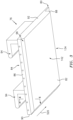
- FIGs. 3 to 5 illustrate one exemplary embodiment of a BOAS segment 76 that may be incorporated into a gas turbine engine, such as the gas turbine engine 20.
- the BOAS segment 76 is an example type of gas turbine engine component. Portions of the BOAS segment 76 includes areas that are exposed to high temperature and other relatively harsh conditions.
- gas turbine engine components face similar harsh conditions. Such components may include vane and blade platforms, burner liner segments, fuel nozzle guides, bulkhead segments, combustors, etc. Although the examples of this disclosure are described with reference to the BOAS segment 76, the other types of gas turbine engine components could also benefit from the teachings of this disclosure, particularly those components having ceramic coating such as thermal barrier coatings and abradable coatings.
- the BOAS segment 76 may include a seal body 80 having a radially inner face 82 (or faces) that faces toward the blade tip 68T a radially outer face 84 (or faces) that faces toward the cavity 75 (See FIG. 2 ).
- the radially inner face 82 (inboard or inner diameter (ID)) and the radially outer face 84 (outboard or outer diameter (OD)) circumferentially extend between a first mate face (circumferential end) 86 and a second mate face (circumferential end) 88 and axially extend between a leading edge face or end 90 and a trailing edge face or end 92.
- a pair of fore-and-aft mounting lugs 94 extend outward from the outer face 84.
- the first mate face 86 meets the radially inner face 82 at an intersection 96.
- intersection 96 There are similar intersections or junctions between the radial interface and the mate face 86, leading edge face 90, and trailing edge face 92.
- the interaction of the blades make the intersection 96 particularly relevant.
- the intersection includes a bevel rather than reflecting a right angle intersection of substrate surfaces.
- FIG. 3 shows a blade sweep direction 520.
- At the intersection of the inner face with the second mate face 88 there are kinetics associated with the releasing of the force from blade tip contact as the blade tip passes out of engagement with one segment and into engagement with the next segment.
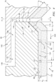
- FIG. 4 shows an intersection between two adjacent BOAS segments 76.
- FIG. 4 shows a ceramic abradable coating system 120 atop a metallic substrate 122.
- the exemplary substrate material is nickel-based superalloy.
- the exemplary coating is shown as a single ceramic layer, there may be multiple ceramic layers.
- PVD physical vapor deposition
- HVAC high velocity air fuel
- exemplary ceramic coatings are stabilized zirconias such as yttria stabilized zirconias (YSZ) and gadolinia stabilized zirconias (GSZ) or combinations.
- the ID surface of the ceramic 120 provides the inner face 82 of the overall blade outer air seal.
- the substrate 122 has a corresponding ID face 124.
- the segment and the substrate may have corresponding portions with the corresponding portions being one in the same except along the coated areas.
- areas of the segment not covered by ceramic coating may be covered by some other coating such as for corrosion protection.
- these other coatings are much thinner than the ceramic coatings.
- Exemplary such other coatings include chromium conversion coatings.
- FIG. 4 shows first and second circumferential end faces 130 and 132 of the substrate along the corresponding mate faces 86 and 88 of the overall segment.
- Cooling passages 134 may have outlets 136 ( FIG. 5 ) to these surfaces.
- the cooling passages may be fed from bypass air introduced through the radially outer face 84 by conventional means (not shown).
- the substrates have a ship lap junction formed by a circumferential OD protrusion 140 from the second mate face 88 accommodated in an OD relief 142 extending from the first mate face of the adjacent segment.
- the interaction leaves a gap having a first (inner) radial segment 144, a circumferential segment 146, and a second (outer) radial segment 148.
- the ID face 124 is provided with an array of recesses 150 such as in the '243 patent.
- the recessing leaves intact protruding material 152 between recesses.
- Exemplary recesses are principally machined circular recesses (e.g., flat bottomed, such as by a plunge end milling) in a regular array (e.g., a square array or a hexagonal array).
- the boundaries 154 between recesses serve as initiation sites for faults 160 which help isolate and accommodate stresses.
- the protruding material is continuous encircling the recesses (e.g., circular recesses have an on-center spacing greater than their diameter).
- the recessing extends to and is modified along the edges of the coated substrate region.
- FIG. 4 shows the substrate 122 as having an edge bevel or chamfer having a surface 170 and the coating having a corresponding bevel or chamfer having a surface 172. Additionally, the recessing extends along the bevel with a recess base 174 (also see FIG. 5 ) shown.
- FIG. 6 shows an exemplary patterning of recesses along the underside.
- the recesses are shown as circular having diameter D 1 and in a hexagonal array leaving a thickness T 1 of intact substrate material at the location of minimum thickness.
- FIG. 4 further shows a recess depth or height of the protruding material as H 1 and an overall coating thickness measured from recess bases of H 2 .
- the substrate bevel on the intact material has a span S 1 .
- the corresponding recess base 174 may have a slightly larger span as is reflected, for example, in FIG. 4 .
- the coating bevel may be approximately the same size as S 1 or may be larger or smaller.
- FIG. 6 shows one aspect of the hexagonal array when applied to a surface having a right angle corner between adjacent edges or ends.
- a main direction of the array is parallel to one edge while a secondary direction is parallel to the other.
- the recesses along the bevels may thus be different for the two edges.
- An exemplary manufacture process may modify any appropriate existing or yet-developed baseline process.
- the substrate may be formed by conventional techniques (e.g., investment casting over casting cores (if any) followed by deshelling/decoring and finish machining).
- the finish machining may leave reference surfaces for the subsequent machining of the recesses as discussed above.
- bondcoat if any
- bondcoat may be applied via appropriate techniques including physical vapor deposition.
- the bondcoat e.g., metallic, if any, may be applied/formed by conventional techniques.
- the ceramic coating may then be applied via vapor deposition and/or spray (as noted above multiple layer coatings are possible).
- a pure spray application e.g., air plasma spray.
- Alternative spray techniques include high velocity oxy-fuel (HVOF) and flame spray.
- HVOF high velocity oxy-fuel
- the spray application may leave excess coating material in order to guarantee sufficient ultimate thickness along the recesses.
- the recesses may print through to the surface of the as-applied coating.
- the coating may then, however, be ground down to a smooth contour eliminating any valleys associated with the recesses but leaving the faults.
- the bevel width or span S 1 is on the order of the size of the recesses (e.g., between the thickness T 1 and 2D 1 , more narrowly between T 1 and T 1 +D 1 .
- exemplary T 1 is 10 mil to 50 mil (0.25 mm to 1.3 mm), more narrowly 15 mil to 30 mil (0.38 mm to 0.76 mm).
- Exemplary D 1 is between 50 mil to 125 mil (1.3 mm to 3.2 mm), more narrowly 70 mil to 100 mil (1.8 mm to 2.5 mm).
- An exemplary bevel angle ⁇ is 20° to 70° off the ID face, more particularly, 30° to 60°.
- the width S 1 is chosen to achieve coating thickness H 2 (along the bevel - FIG. 4 ) to width S 1 ratio of 1:3 to 1:1 which relieves some of the stress from sintering shrinkage and promotes spallation resistance and surface temperature capability. In some less demanding applications, the ratio of thickness H 2 to width S 1 may be as small as 1:5.
- FIG. 4 is not to scale/proportion. Also, although not shown, a further variation could extend the recesses radially farther along the unbeveled portions of the faces 130, 132 (particularly where those unbeveled portions also were coated). Also, in the illustrated FIG. 4 configuration, H 2 and H 1 , measured normal to the actual surface (and not to the pre-bevel surface) are lower along the bevel than along unbeveled substrate. This is not required. They may be the same.
- the pair of bevels brings TBC further radially outboard while beveling the square metallic edge which reduces heat load and base metal temperature and also reduces the temperature of the intersegment edge as the bevel helps to reduce hot gas impingement along the edges of the intersegment gap.
- the bevel also serves to reduce stress concentration by eliminating the square ground corners of TBC and base metal.
- these faults may be in the as-applied coating as non-crack regions of the coating structure where little or no strength has been developed in the planar directions. This is due to simultaneous deposition on the raised and recessed features which results in the lower coating regions building up alongside the raised regions where little to no bonding occurs. This low strength region acts as an expansion joint to achieve strain tolerance.
- the faults may form as cracks during thermal cycling after initial deposition.
- Some variations include omitting the array of recesses 150 and only having recessing along the bevel. Other variations may extend an array of recesses only slightly inward along intact surface 124 but not along the entire footprint of the BOAS or other article.
- Alternative substrates include ceramic matrix composites (CMC) such as SiC-SiC. These may favor alternative coatings such as those comprising (e.g., at least 50% by weight) one or more of hafnia, hafnium silicate and yttrium silicate.
- CMC ceramic matrix composites
- first, second, and the like in the following claims is for differentiation within the claim only and does not necessarily indicate relative or absolute importance or temporal order. Similarly, the identification in a claim of one element as “first” (or the like) does not preclude such "first” element from identifying an element that is referred to as “second” (or the like) in another claim or in the description.
Landscapes
- Engineering & Computer Science (AREA)
- Mechanical Engineering (AREA)
- General Engineering & Computer Science (AREA)
- Chemical & Material Sciences (AREA)
- Combustion & Propulsion (AREA)
- Materials Engineering (AREA)
- Ceramic Engineering (AREA)
- Turbine Rotor Nozzle Sealing (AREA)
- Non-Metallic Protective Coatings For Printed Circuits (AREA)
Applications Claiming Priority (2)
| Application Number | Priority Date | Filing Date | Title |
|---|---|---|---|
| US16/184,108 US11131206B2 (en) | 2018-11-08 | 2018-11-08 | Substrate edge configurations for ceramic coatings |
| EP19208107.3A EP3650573B1 (fr) | 2018-11-08 | 2019-11-08 | Configurations de bord de substrat pour revêtements céramiques |
Related Parent Applications (1)
| Application Number | Title | Priority Date | Filing Date |
|---|---|---|---|
| EP19208107.3A Division EP3650573B1 (fr) | 2018-11-08 | 2019-11-08 | Configurations de bord de substrat pour revêtements céramiques |
Publications (2)
| Publication Number | Publication Date |
|---|---|
| EP4545681A2 true EP4545681A2 (fr) | 2025-04-30 |
| EP4545681A3 EP4545681A3 (fr) | 2025-07-30 |
Family
ID=68501501
Family Applications (2)
| Application Number | Title | Priority Date | Filing Date |
|---|---|---|---|
| EP19208107.3A Active EP3650573B1 (fr) | 2018-11-08 | 2019-11-08 | Configurations de bord de substrat pour revêtements céramiques |
| EP25159458.6A Pending EP4545681A3 (fr) | 2018-11-08 | 2019-11-08 | Configurations de bord de substrat pour revêtements céramiques |
Family Applications Before (1)
| Application Number | Title | Priority Date | Filing Date |
|---|---|---|---|
| EP19208107.3A Active EP3650573B1 (fr) | 2018-11-08 | 2019-11-08 | Configurations de bord de substrat pour revêtements céramiques |
Country Status (2)
| Country | Link |
|---|---|
| US (3) | US11131206B2 (fr) |
| EP (2) | EP3650573B1 (fr) |
Families Citing this family (6)
| Publication number | Priority date | Publication date | Assignee | Title |
|---|---|---|---|---|
| US12152502B2 (en) * | 2021-10-29 | 2024-11-26 | Pratt & Whitney Canada Corp. | Selectively coated gas path surfaces within a hot section of a gas turbine engine |
| US11913340B2 (en) * | 2022-06-17 | 2024-02-27 | Rtx Corporation | Air seal system with backside abradable layer |
| US12012870B1 (en) | 2022-11-29 | 2024-06-18 | Rtx Corporation | Machinable coating for CMC and metal interface in a turbine section |
| US12110798B1 (en) * | 2024-01-31 | 2024-10-08 | Rtx Corporation | Blade outer air seal with machinable coating |
| US12503953B2 (en) * | 2024-02-13 | 2025-12-23 | Rtx Corporation | Ceramic matrix composite component with coating |
| US20260078685A1 (en) * | 2024-09-19 | 2026-03-19 | Rtx Corporation | Thermal barrier coating for edge component |
Citations (3)
| Publication number | Priority date | Publication date | Assignee | Title |
|---|---|---|---|---|
| US8506243B2 (en) | 2009-11-19 | 2013-08-13 | United Technologies Corporation | Segmented thermally insulating coating |
| US20160003087A1 (en) | 2013-02-26 | 2016-01-07 | United Technologies Corporation | Edge treatment for gas turbine engine component |
| US20160251970A1 (en) | 2013-10-02 | 2016-09-01 | United Technologies Corporation | Segmented ceramic coating interlayer |
Family Cites Families (19)
| Publication number | Priority date | Publication date | Assignee | Title |
|---|---|---|---|---|
| FR2637838B1 (fr) * | 1988-10-14 | 1991-01-25 | Europ Propulsion | Procede de fabrication de pieces composites constituees d'un voile et d'un renfort |
| GB9414858D0 (en) * | 1994-07-22 | 1994-09-14 | Baj Coatings Ltd | Protective coating |
| US5619889A (en) * | 1994-10-11 | 1997-04-15 | Fed Corporation | Method of making microstructural surgical instruments |
| US6158961A (en) * | 1998-10-13 | 2000-12-12 | General Electric Compnay | Truncated chamfer turbine blade |
| FR2832180B1 (fr) * | 2001-11-14 | 2005-02-18 | Snecma Moteurs | Revetement abradable pour parois de turbines a gaz |
| US8303247B2 (en) | 2007-09-06 | 2012-11-06 | United Technologies Corporation | Blade outer air seal |
| US8079806B2 (en) * | 2007-11-28 | 2011-12-20 | United Technologies Corporation | Segmented ceramic layer for member of gas turbine engine |
| US10113435B2 (en) * | 2011-07-15 | 2018-10-30 | United Technologies Corporation | Coated gas turbine components |
| US9995165B2 (en) | 2011-07-15 | 2018-06-12 | United Technologies Corporation | Blade outer air seal having partial coating |
| US20130340966A1 (en) * | 2012-06-21 | 2013-12-26 | United Technologies Corporation | Blade outer air seal hybrid casting core |
| WO2015088839A1 (fr) * | 2013-12-10 | 2015-06-18 | Saint-Gobain Ceramics & Plastics, Inc. | Article réfractaire |
| US9765639B2 (en) * | 2014-01-10 | 2017-09-19 | Solar Turbines Incorporated | Gas turbine engine with exit flow discourager |
| US20190195080A1 (en) | 2014-08-06 | 2019-06-27 | United Technologies Corporation | Ceramic coating system and method |
| US20160040551A1 (en) | 2014-08-06 | 2016-02-11 | United Technologies Corporation | Geometrically segmented coating on contoured surfaces |
| US11098399B2 (en) * | 2014-08-06 | 2021-08-24 | Raytheon Technologies Corporation | Ceramic coating system and method |
| US10273192B2 (en) * | 2015-02-17 | 2019-04-30 | Rolls-Royce Corporation | Patterned abradable coating and methods for the manufacture thereof |
| US9759079B2 (en) | 2015-05-28 | 2017-09-12 | Rolls-Royce Corporation | Split line flow path seals |
| US10138748B2 (en) * | 2016-01-15 | 2018-11-27 | United Technologies Corporation | Gas turbine engine components with optimized leading edge geometry |
| GB201603556D0 (en) | 2016-03-01 | 2016-04-13 | Rolls Royce Plc | An intercomponent seal for a gas turbine engine |
-
2018
- 2018-11-08 US US16/184,108 patent/US11131206B2/en active Active
-
2019
- 2019-11-08 EP EP19208107.3A patent/EP3650573B1/fr active Active
- 2019-11-08 EP EP25159458.6A patent/EP4545681A3/fr active Pending
-
2021
- 2021-07-26 US US17/385,003 patent/US11920478B2/en active Active
-
2024
- 2024-03-05 US US18/596,421 patent/US12460555B2/en active Active
Patent Citations (3)
| Publication number | Priority date | Publication date | Assignee | Title |
|---|---|---|---|---|
| US8506243B2 (en) | 2009-11-19 | 2013-08-13 | United Technologies Corporation | Segmented thermally insulating coating |
| US20160003087A1 (en) | 2013-02-26 | 2016-01-07 | United Technologies Corporation | Edge treatment for gas turbine engine component |
| US20160251970A1 (en) | 2013-10-02 | 2016-09-01 | United Technologies Corporation | Segmented ceramic coating interlayer |
Also Published As
| Publication number | Publication date |
|---|---|
| EP4545681A3 (fr) | 2025-07-30 |
| US20240254889A1 (en) | 2024-08-01 |
| US20210355838A1 (en) | 2021-11-18 |
| US11920478B2 (en) | 2024-03-05 |
| EP3650573B1 (fr) | 2025-02-26 |
| US11131206B2 (en) | 2021-09-28 |
| US20200149426A1 (en) | 2020-05-14 |
| US12460555B2 (en) | 2025-11-04 |
| EP3650573A1 (fr) | 2020-05-13 |
Similar Documents
| Publication | Publication Date | Title |
|---|---|---|
| US12460555B2 (en) | Substrate edge configurations for ceramic coatings | |
| EP2325347B1 (fr) | Revêtement à isolation thermique segmenté | |
| US8047771B2 (en) | Turbine nozzles and methods of manufacturing the same | |
| CN1840329B (zh) | 分层体构件 | |
| US9938899B2 (en) | Hot gas path component having cast-in features for near wall cooling | |
| US20200149431A1 (en) | Cost effective manufacturing method for gsac incorporating a stamped preform | |
| US10648349B2 (en) | Method of manufacturing a coated turbine blade and a coated turbine vane | |
| EP4119773A1 (fr) | Système d'étanchéité ayant une couche de silicium et une couche barrière | |
| US20180135451A1 (en) | Endwall arc segments with cover across joint | |
| EP3967845B1 (fr) | Agencement de refroidissement diffusé pour composants de moteur à turbine à gaz | |
| EP3907375B1 (fr) | Revêtement de barrière thermique avec contrainte d'amorçage réduite des fissures sur les bords et facteur d'isolation élevé | |
| EP2937514B1 (fr) | Pointe d'aube de turbine de moteur à turbine à gaz avec évidement revêtu | |
| EP3421729B1 (fr) | Revêtement d'étanchéité d'alumine ayant une couche intermédiaire | |
| US20260110096A1 (en) | Turbine blade outermost abrasive layer using graded ceramics | |
| EP4636224A1 (fr) | Revêtement segmenté géométriquement pour isolation thermique et protection contre l'abradabilité | |
| EP3556998B1 (fr) | Joint d'air ayant une partie de trajectoire de gaz comportant un revêtement segmenté géométriquement | |
| US12618332B2 (en) | Gas turbine engine | |
| US20250179923A1 (en) | Gas turbine engine | |
| US20240286960A1 (en) | Coating system and method for maintenance thereof |
Legal Events
| Date | Code | Title | Description |
|---|---|---|---|
| PUAI | Public reference made under article 153(3) epc to a published international application that has entered the european phase |
Free format text: ORIGINAL CODE: 0009012 |
|
| STAA | Information on the status of an ep patent application or granted ep patent |
Free format text: STATUS: THE APPLICATION HAS BEEN PUBLISHED |
|
| AC | Divisional application: reference to earlier application |
Ref document number: 3650573 Country of ref document: EP Kind code of ref document: P |
|
| AK | Designated contracting states |
Kind code of ref document: A2 Designated state(s): AL AT BE BG CH CY CZ DE DK EE ES FI FR GB GR HR HU IE IS IT LI LT LU LV MC MK MT NL NO PL PT RO RS SE SI SK SM TR |
|
| REG | Reference to a national code |
Ref country code: DE Ref legal event code: R079 Free format text: PREVIOUS MAIN CLASS: C23C0024000000 Ipc: F01D0005000000 |
|
| PUAL | Search report despatched |
Free format text: ORIGINAL CODE: 0009013 |
|
| AK | Designated contracting states |
Kind code of ref document: A3 Designated state(s): AL AT BE BG CH CY CZ DE DK EE ES FI FR GB GR HR HU IE IS IT LI LT LU LV MC MK MT NL NO PL PT RO RS SE SI SK SM TR |
|
| RIC1 | Information provided on ipc code assigned before grant |
Ipc: F01D 5/00 20060101AFI20250624BHEP Ipc: F01D 5/20 20060101ALI20250624BHEP Ipc: F01D 5/28 20060101ALI20250624BHEP Ipc: F01D 9/00 20060101ALI20250624BHEP Ipc: F01D 11/00 20060101ALI20250624BHEP Ipc: F01D 11/08 20060101ALI20250624BHEP Ipc: F01D 11/12 20060101ALI20250624BHEP Ipc: B23P 15/00 20060101ALI20250624BHEP Ipc: C23C 4/04 20060101ALI20250624BHEP Ipc: C23C 18/00 20060101ALI20250624BHEP Ipc: F01D 25/00 20060101ALI20250624BHEP Ipc: F23R 3/00 20060101ALI20250624BHEP Ipc: C23C 4/08 20160101ALI20250624BHEP Ipc: F01D 25/24 20060101ALI20250624BHEP |
|
| STAA | Information on the status of an ep patent application or granted ep patent |
Free format text: STATUS: REQUEST FOR EXAMINATION WAS MADE |
|
| 17P | Request for examination filed |
Effective date: 20260130 |