EP4545724A1 - Elément de support pour la réalisation de planchers et/ou planchers de bâtiments - Google Patents
Elément de support pour la réalisation de planchers et/ou planchers de bâtiments Download PDFInfo
- Publication number
- EP4545724A1 EP4545724A1 EP24208494.5A EP24208494A EP4545724A1 EP 4545724 A1 EP4545724 A1 EP 4545724A1 EP 24208494 A EP24208494 A EP 24208494A EP 4545724 A1 EP4545724 A1 EP 4545724A1
- Authority
- EP
- European Patent Office
- Prior art keywords
- supporting element
- element according
- rails
- elements
- longitudinal
- Prior art date
- Legal status (The legal status is an assumption and is not a legal conclusion. Google has not performed a legal analysis and makes no representation as to the accuracy of the status listed.)
- Pending
Links
Images












Classifications
-
- E—FIXED CONSTRUCTIONS
- E04—BUILDING
- E04C—STRUCTURAL ELEMENTS; BUILDING MATERIALS
- E04C2/00—Building elements of relatively thin form for the construction of parts of buildings, e.g. sheet materials, slabs, or panels
- E04C2/30—Building elements of relatively thin form for the construction of parts of buildings, e.g. sheet materials, slabs, or panels characterised by the shape or structure
- E04C2/38—Building elements of relatively thin form for the construction of parts of buildings, e.g. sheet materials, slabs, or panels characterised by the shape or structure with attached ribs, flanges, or the like, e.g. framed panels
- E04C2/384—Building elements of relatively thin form for the construction of parts of buildings, e.g. sheet materials, slabs, or panels characterised by the shape or structure with attached ribs, flanges, or the like, e.g. framed panels with a metal frame
-
- E—FIXED CONSTRUCTIONS
- E04—BUILDING
- E04B—GENERAL BUILDING CONSTRUCTIONS; WALLS, e.g. PARTITIONS; ROOFS; FLOORS; CEILINGS; INSULATION OR OTHER PROTECTION OF BUILDINGS
- E04B5/00—Floors; Floor construction with regard to insulation; Connections specially adapted therefor
- E04B5/02—Load-carrying floor structures formed substantially of prefabricated units
- E04B5/10—Load-carrying floor structures formed substantially of prefabricated units with metal beams or girders, e.g. with steel lattice girders
-
- E—FIXED CONSTRUCTIONS
- E04—BUILDING
- E04B—GENERAL BUILDING CONSTRUCTIONS; WALLS, e.g. PARTITIONS; ROOFS; FLOORS; CEILINGS; INSULATION OR OTHER PROTECTION OF BUILDINGS
- E04B5/00—Floors; Floor construction with regard to insulation; Connections specially adapted therefor
- E04B5/02—Load-carrying floor structures formed substantially of prefabricated units
- E04B5/14—Load-carrying floor structures formed substantially of prefabricated units with beams or girders laid in two directions
-
- E—FIXED CONSTRUCTIONS
- E04—BUILDING
- E04B—GENERAL BUILDING CONSTRUCTIONS; WALLS, e.g. PARTITIONS; ROOFS; FLOORS; CEILINGS; INSULATION OR OTHER PROTECTION OF BUILDINGS
- E04B1/00—Constructions in general; Structures which are not restricted either to walls, e.g. partitions, or floors or ceilings or roofs
- E04B1/18—Structures comprising elongated load-supporting parts, e.g. columns, girders, skeletons
- E04B1/24—Structures comprising elongated load-supporting parts, e.g. columns, girders, skeletons the supporting parts consisting of metal
- E04B2001/2484—Details of floor panels or slabs
Definitions
- the invention relates to a supporting element for constructing ceilings and/or floors of buildings according to the preamble of claim 1.
- load-bearing elements are placed together and connected to the respective vertical building structure.
- connecting the load-bearing elements to one another is only possible if the functional element is not yet incorporated into the load-bearing element.
- Functional elements include, for example, insulation material, soundproofing materials, installations, and the like.
- the functional element can only be inserted once the load-bearing elements are connected to one another. Since the load-bearing elements can only be fitted with the respective functional element after they have been connected to one another and to the building structure, this procedure is very complex and laborious.
- the invention is based on the object of designing the generic support element in such a way that it can be used to easily connect the ceilings/floors to the building structure.
- the support element according to the invention has the assembly opening located in the projecting edge of the support element. This makes the assembly opening accessible for assembly even when the support element is delivered ready for installation to the installation site. It is then only necessary to connect the prefabricated and ready-to-install support elements to each other and to the The trough-shaped design allows for complete prefabrication of the supporting element in the workshop.
- the support element can also be completely assembled at the installation site.
- the supporting element advantageously has a frame made of plug-in parts that can be easily assembled. After the plug-in process, the frame parts can be easily and firmly connected to one another.
- the frame is formed by profile rails. This allows the profile rails to be designed in such a way that they are adapted to the specific application of the supporting element.
- profile rails are particularly cost-effective and easy to manufacture when made from roll-formed steel profiles.
- the profile rails can also be made from aluminum or wood profiles with appropriate profiling.
- the profile rails are connected at their ends by connectors.
- the connectors first plug the profile rails together and then firmly connect them, preferably using screw connections.
- the frame of the supporting element can be easily manufactured in this way.
- the connecting pieces are advantageously metal profile pieces.
- Such metal profile pieces are preferably angle pieces with legs that are at an angle, preferably at right angles to each other. Since the frame of the supporting element usually has a square, particularly rectangular, outline, the legs of the angle pieces are correspondingly at right angles to each other. They are attached to the inside of the profile rails, which are at the same angle to each other.
- the metal profile pieces preferably the angle pieces, are arranged within the frame and thus the supporting element, they are protected after installation so that there is no risk of them being damaged or even destroyed.
- the profile rails are preferably C-shaped. They have a web connecting two transversely projecting legs with angled edge sections running toward each other. This profile shape gives the profile rails high strength.
- the profile rails form the longitudinal and transverse rails of the frame. Therefore, different profile rails are not required for the different sides of the frame. This greatly contributes to cost-effective production and easy assembly of the support element in the workshop.
- the framework is advantageously provided with stiffening.
- This stiffening advantageously comprises at least one longitudinal stiffener, which connects opposing frame sides to each other.
- the term "longitudinal stiffener” is primarily associated with rectangular frames that have a longitudinal extension. However, a longitudinal stiffener can also be understood as a stiffener that connects two opposing frame sides of a square frame.
- the stiffening of the frame advantageously also comprises at least one transverse stiffening.
- this transverse stiffener connects the longitudinal stiffener to opposite frame sides.
- the transverse stiffener extends perpendicular to the longitudinal stiffener and thus also perpendicular to the corresponding frame sides.
- a particularly advantageous, easy-to-create longitudinal reinforcement is achieved when it is formed by two adjacent profile rails. These are also advantageously C-shaped.
- the two rails are placed together with their webs adjacent to each other, so that their legs run opposite each other from the webs. With the two adjacent profile rails, the longitudinal reinforcement and thus the frame are highly rigid.
- a particularly advantageous feature contributing to simple assembly is that the profile rails of the longitudinal reinforcement are attached at their ends to the frame sides lying transversely to them by angled connecting elements.
- These connecting elements are advantageously housed in a protected manner within the frame, with the connecting elements having angled, preferably perpendicular, legs that are attached to the inside of the transverse frame sides and to the opposite outer sides of the profile rails of the longitudinal reinforcement.
- the connecting elements are preferably metal profile pieces.
- the simple assembly of the supporting element according to the invention is further advantageously facilitated by the fact that the transverse reinforcement is formed by profile rails, the ends of which are pushed onto connecting pieces on the longitudinal reinforcement and on the opposite frame sides and are then firmly connected to these connecting pieces.
- the connecting pieces which are advantageously metal profile pieces, have a contour shape such that the profile rails of the transverse reinforcement can be pushed onto them in such a way that they are firmly attached to the connecting pieces. Then the profile rails can be attached to the connecting pieces easily and reliably, preferably using a screw connection.
- Another advantageous design involves stiffening the structure with a cross-braced cable tensioning system. This requires minimal installation space, is inexpensive to purchase, and is easy to install.
- the cross-bracing cable bracing comprises at least two intersecting cables, the ends of which are fastened to the frame within the supporting element.
- the ropes can be made in one piece, but can also consist of at least two rope sections.
- the cables can extend the entire length of the supporting element. Depending on the length of the supporting element, it is also possible for the supporting element to have two or more cross-braced cable bracings.
- coupling elements are advantageously arranged on those frame parts via which the supporting element is to be connected to the vertical building structure.
- the coupling element is an angle piece having two legs positioned at an angle, preferably at right angles to each other.
- One leg is attached, preferably screwed, to the outside of the corresponding frame part.
- the other leg then projects transversely from the frame part to the outside and serves as the connection to the Building structure.
- a corresponding number of coupling elements can be provided to ensure reliable attachment of the load-bearing element to the building structure.
- the edge of the frame that protrudes beyond the top and/or bottom is provided with at least one support for at least one cover part.
- This cover part is preferably plate-shaped and rests on the support.
- the cover part covers the functional element located in the frame from the outside and is preferably screwed to the support.
- the support for the cover part is particularly advantageously formed by a profile section of the profile rails. If the profile rails have a C-shaped configuration, the support is advantageously formed by angled free ends of the edge sections of these profile rails. In this case, the support advantageously extends over the entire length of the profile rails, allowing the cover part to be securely attached to the frame along its circumference.
- the support for the cover part is arranged in the area below the installation opening, so that despite the cover part being above the installation opening, a simple connection of adjacent supporting elements to create the ceiling and/or floors is possible without any problems.
- a further advantageous design is achieved when parts of building installations are housed in the supporting element.
- building installations include, for example, heating and cooling systems, cooling and heating pipes, electrical and IT cabling, water supply and sewage pipes, sprinkler systems, and the like.
- the mounting opening of the support element advantageously serves to connect adjacent support elements by means of connecting elements.
- the supporting elements lie against each other with their corresponding frame sides and are firmly held together by the connecting elements.
- the connecting element has a screw sleeve provided with a transversely projecting stop at one end, into which a screw spindle can be screwed.
- An angle screwdriver is advantageously used for this purpose.
- the support elements described below each have a supporting frame, which advantageously consists of roll-formed, preferably galvanized steel profiles. These are bolted together using efficiently manufactured connecting brackets.
- the supporting frame is advantageously designed so that at least one support plate can be attached to the top and bottom.
- Support plates are attached to the supporting framework at the top and bottom to define a ceiling cavity.
- the upper support plate serves as Support for a floor structure to be installed on site, which may include, for example, impact sound insulation, screed, and floor covering.
- the lower support plate provides support for cavity insulation and is used to attach installations and supply lines integrated into the supporting elements.
- the support plates can also take on the function of a static brace.
- the cavity between the support plates and the steel profile parts is advantageously completely filled with an insulating material.
- This insulating material can be blown into the cavities.
- Foam material can also be used as an insulating material, which, when expanded, completely fills the cavities easily and quickly.
- the support elements are designed so that they can be easily connected to one another at the installation site, particularly by means of a screw connection.
- An angle screwdriver is advantageously used for this purpose. This avoids the need for individual assembly of the support element on site.
- Heating and cooling ceiling systems can be pre-assembled into the supporting element in the factory.
- the lower ceiling cladding and the floor structure, such as screed, are produced on site in the conventional manner.
- the supporting element is largely manufactured as a frame element prefabricated in the workshop so that it can be very quickly assembled, suspended and coupled at the construction site.
- the supporting element has a load-bearing function and can be easily suspended or attached to a vertical building structure in a manner to be described below.
- the load-bearing elements By connecting the ceiling modules in a rapid assembly method, the load-bearing elements allow a ceiling-to-surface structure to be created, forming a stiffening load-bearing plate capable of absorbing all loads.
- loads include vertical loads, such as dead weight, traffic and snow loads, horizontal loads, primarily wind loads, and special loads, such as those that occur during earthquakes.
- the stiffening effect of the surface structure formed from the load-bearing elements also ensures that the horizontal forces that occur are specifically transferred to the vertical load-bearing structure of the building, which means that the deformations of the building are extremely small.
- FIG. 1 A building is shown schematically. It has upright posts 1 that are connected to each other at the top and bottom by horizontal crossbeams 2.
- the posts 1 advantageously consist of sections 1a that sit one on top of the other and are firmly connected to each other.
- the posts 1 and the crossbeams 2 form facade load-bearing elements 3 that are arranged above and next to each other.
- Each facade load-bearing element 3 has fields 4 that are delimited by the posts 1 and the crossbeams 2.
- the fields 4 serve to accommodate building elements such as glass windows, wall elements, and the like.
- Bracing modules (not shown) can be accommodated in all fields 4 or in individual fields. They are provided depending on the design of the supporting structure so that it has the desired stability.
- the building has a ceiling 5 and two floors 6, 7, each of which defines a storey and each has load-bearing elements 8.
- the supporting elements 8 of the ceiling 5 are fastened with their narrow sides to the upper ends of the sections of the posts 1 of the facade supporting elements 3 in a manner to be described below.
- the supporting elements 8 of the floors 6, 7 are fastened, in a manner to be described below, to the upper ends of post sections 1a arranged one above the other, which form the posts.
- Fig. 2 shows an embodiment of support elements 8, which are placed together with their longitudinal sides and, when installed in the building, form components of the ceiling 5 or the floor 6, 7.
- the support elements 8, which are placed together with their longitudinal sides, are advantageously screwed together so that they can be separated from each other if necessary, for example if one of the support elements 8 is damaged and needs to be replaced or repaired.
- the majority of the support elements 8 are of identical design. In the central region, the support elements 8 are shorter because the component formed from the support elements 8 is provided with an opening 9 at the edge. This opening has a rectangular outline.
- the built-in part formed from the supporting elements 8 can also be provided without such an opening 9 or with further openings 9, depending on the desired design of the built-in part.
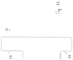
- the longitudinal rails 10 have a C-profile ( Fig. 10 and 25 to 28 ).
- the longitudinal rails 10 have a flat web 11 connecting two parallel legs 12, which run perpendicular to the web 11 and merge into edge sections 13 at their free ends. Like the legs 12, they are flat and lie parallel to the web 11.
- the free end 14 of the edge sections 13 is bent outwards at a right angle.
- the two free ends 14 are parallel to each other and, like the edge sections 13, are flat.
- cross rails 15 ( Fig. 6 and 31 to 34 ), which have the same cross-sectional design as the longitudinal rails 10, but are shorter than them.
- Angle-shaped connecting pieces 16 ( Fig. 6 ), which are fastened in the corner area of the support element 8 to the inside of the webs 11 of the longitudinal rails 10 and the cross rails 15.
- the connecting pieces 16 have two angled legs 16a, 16b, which in the exemplary embodiment are perpendicular to one another, of which the legs 16a are fastened to the inside of the webs 11 of the longitudinal rails 10 and the legs 16b are fastened to the inside of the webs 11 of the cross rails 15.
- the connecting pieces 16 are screwed to the longitudinal rails 10 and to the cross rails 15, so that the support elements 8 can be easily dismantled if necessary.
- the legs 16a, 16b of the connecting pieces 16 advantageously extend over the entire height of the webs 11 of the longitudinal rails 10 and the transverse rails 15.
- connecting pieces 16 are arranged on the inner sides of the webs 11, they are not visible from the outside and are also protected from damage when the supporting elements are in use.
- the two parallel cross rails 15 are connected to each other by a longitudinal stiffener 17, which runs parallel to the longitudinal rails 10 and is provided halfway along the length of the cross rails 15 ( Fig. 5 ).
- the longitudinal stiffener 17 is formed by two rails which are of the same design as the longitudinal rails 10. Therefore, these two rails forming the longitudinal stiffener 17 are also provided with the reference numeral 10.
- the two rails 10 of the longitudinal stiffener 17 are arranged mirror-inverted to each other in such a way that their webs 11 lie against each other ( Fig. 10 ).
- the connecting pieces 18 are advantageously detachably connected to the cross rails 15 and the rails 10 of the longitudinal stiffener 17.
- One leg 18a of the connecting pieces 18 is fastened, preferably screwed, to the inside of the web 11 of the cross rails 15, while the other legs 18b, which are perpendicular to them, are fastened, preferably screwed, to the inside of the webs 11 of the rails 10 of the longitudinal stiffener 17.
- the longitudinal stiffener 17 In the area where the ends of the longitudinal stiffener 17 connect to the cross rails 15, these are provided with a recess 19, 20 ( Fig. 5 and 32 ). This allows the longitudinal stiffener 17 and the cross rails 15 to be connected to one another in such a way that their upper and lower sides are at least approximately flush with one another ( Fig. 6 ). The longitudinal stiffener 17 projects with its ends into the recesses 19, 20 ( Fig. 5 ).
- the longitudinal stiffener 17 is also connected to the longitudinal rails 10 via cross braces 22.
- the cross braces 22 are of identical design and are each formed by a profile rail with a C-shaped cross section.
- the cross braces 22 are distributed along the length of the longitudinal stiffener 17 and are advantageously spaced equally apart.
- the cross braces 22 are advantageously provided such that the cross rails 15 are also spaced equally apart from the adjacent cross braces 22 as these, in turn, are spaced equally apart.
- connecting pieces 24, 25 are provided, which are advantageously of identical design.
- the connecting pieces 24 ( Fig. 3 ) are provided on the inner sides of the webs 11 of the rails 10 facing away from each other, while the connecting pieces 25 of the longitudinal rails 10 ( Fig. 6 ) are arranged on the mutually facing inner sides of the webs 11 of the longitudinal rails 10 ( Fig. 6 ).
- the free ends 14 of the edge sections 13 of the rails 10 of the longitudinal stiffener 17 are each provided with a recess 26.
- the connecting pieces 26 are first pushed into the rails 10 from the ends and positioned and fastened, preferably screwed on.
- the cross braces 22 are then placed with one end transversely to the rails 10 of the longitudinal stiffener 17 and fastened to the connecting pieces 24.
- the longitudinal rails 10 provided with the connecting pieces 25 are placed transversely to the cross struts 22 (arrows in Fig. 6 ).
- the cross struts 22 are attached by their free ends to the connecting pieces 25.
- the legs 16b of the connecting pieces 16 at the ends of the longitudinal rails 10 engage the ends of the cross rails 15 and are connected to them in the manner described.
- the longitudinal rails 10 also have recesses 27 in the area of the connecting pieces 25, which are provided in the free ends 14 of the edge sections 13 of the longitudinal rails 10.
- the recesses 26, 27 are also designed so that they are filled by the cross struts 22 in the assembled position ( Fig. 7 ).
- the upper and lower sides of the cross braces 22 are advantageously flush with the upper side of the wall sections 13 of the longitudinal rails 10 when mounted.
- the upper and lower sides of the rails 10 of the longitudinal reinforcement 10 are advantageously flush with the upper side of the edge sections 13 of the cross rails 15 when mounted. Fig. 7 ).
- the angled free ends 14 of the edge sections 13 of the longitudinal rails 10 and the transverse rails 15 form supports for cover parts 28 ( Fig. 8 and 9 ), with which the top and bottom of the support elements 8 are covered.
- the cover parts 28 are preferably plate-shaped and rest with their longitudinal and transverse edges on the free ends 14 of the edge sections 13 of the longitudinal rails 10 and the transverse rails 15.
- the plate-shaped cover parts 28 rest on the transverse struts 22
- the cover parts 28 can be attached to the support element 8 in a suitable manner.
- the outer sides of the cover parts 28 are flush with the upper sides of the free ends 14 of the edge sections 13 of the longitudinal rails 10 and the transverse rails 15.
- the support elements 8 have a continuously flat upper and lower side to the edge, which considerably facilitates and simplifies the installation of the support elements 8 within the building.
- the panels 23 of the supporting element 8, which are covered upwards and downwards by the cover parts 28, advantageously accommodate the insulating material, which preferably completely fills the panels 23.
- the insulating material can be blown into the panels 23. If foam material is used as the insulating material, this material can completely fill the panels 23 by foaming.
- the cover parts 28 are advantageously sheet metal parts that can be easily cut to the required size and are also inexpensive to manufacture.
- the supporting elements 8 are connected to each other with their long sides adjacent to each other ( Fig. 1 and 9 to 11 ).
- the webs 11 of the longitudinal rails 10 of the adjacent supporting elements 8 there are passages 29 distributed over their length ( Fig. 11 ), through which connecting elements 30 can be inserted.
- They have a screw sleeve 31 which is provided at one end with a transversely projecting stop 32, with which the screw sleeve 31 rests against the web 11 of one longitudinal rail 10.
- a screw spindle 34 is screwed into the screw sleeve 31 with the aid of an angle screwdriver 33, the head 35 of which, when screwed in, rests against the web 11 of the other longitudinal rail 10, whereby the two adjacent longitudinal rails 10 of the adjacent support elements 8 are firmly connected to one another.
- the adjacent support elements 8 can be firmly connected to one another.
- the passages 29 for the connecting elements 30 are located in the area between the cover parts 28 or free ends 14 of the edge sections 13 and the legs 12 of the longitudinal rails 10 ( Fig. 10 , 25, 27 and 28 ). This makes it possible to connect the supporting elements 8 only after they have been completely finished. Once the supporting elements 8 have been connected, no further work on the supporting element 8 is required.
- coupling elements 36 are provided in the corner area on the cross rails 15 ( Fig. 8 , 12 and 13 ).
- the coupling elements 36 are identically designed and are formed by angle pieces with two legs 36a and 36b positioned at right angles to each other.
- Leg 36a rests against the outer side of the cross rail 15 and is preferably screwed to it.
- the leg 36b projecting at a right angle, serves to connect or fasten the supporting element 8 to the respective post 1 of the building.
- the two legs 36a, 36b of the coupling element 36 have, for example, the same width and height. Since the legs 36a, 36b rest flat against the outer sides of the cross rails 15 and the longitudinal sides of the hollow beam 37, secure fastening of the supporting elements is ensured.
- the coupling elements 36 may also have a different shape.
- the coupling elements 36 are preferably screwed to the supporting elements 8 and to the posts 1, simple assembly and disassembly is possible.
- the legs 16b of the connecting pieces 16 and the legs 36a of the coupling elements 36 are at the same height, but on different sides of the webs 11 of the cross rails 15. This allows the legs 16b, 36a to be connected together by means of fastening elements 38 ( Fig. 12 ), preferably screw elements, to the cross rails 15. At least the legs 16b, 36a of the connecting pieces 16 and the coupling elements 36 are of identical design.
- the connecting pieces 16 and the coupling elements 36 are of identical design, so that different types of connecting/coupling pieces do not have to be manufactured.
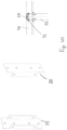
- the Figs. 14 and 15 show in detail the connecting piece 16, with which the longitudinal rails 10 are connected to the transverse rails 15 in the manner described.
- the two legs 16a, 16b are perpendicular to each other and each have several through-openings 39 for the corresponding fastening elements.
- the two legs 16a, 16b have the same width and height.
- the coupling elements 36 are arranged slightly offset relative to the connecting pieces 16. This results in the leg 36b being slightly set back inward relative to the leg 16a. Accordingly, the leg 36a protrudes inward beyond the leg 16b by a corresponding amount. This offset advantageously ensures that adjacent support elements 8 can lie perfectly against one another with their longitudinal rails 10.
- the holding piece 21, with which the two connecting pieces 18 assigned to the longitudinal stiffener 17 are held, has, for example, a quadrangular, in particular square, outline ( Fig. 17 ). It is a flat holding part with corresponding through-openings 40 for fastening elements 41.
- the thin holding piece 21 requires only a small amount of installation space, which has an advantageous effect on the compact design of the ceiling 5 and floors 6, 7 formed from the supporting elements 8.
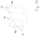
- Fig. 19 shows in detail the design of the connecting pieces 18, with which the rails 10 of the longitudinal stiffener 17 are connected to the cross rails 15 in the manner described.
- the connecting piece 18 is designed as an angle piece and has the two legs 18a, 18b, which have the same height. However, the leg 18a is narrower than the leg 18b, which in the installed position is attached in the manner described to the rails 10 of the longitudinal stiffener 17.
- the narrow web 18a lies on the inside of the web 11 ( Fig. 5 ) of the cross rail 15 and is secured by means of the fastening elements 41 ( Fig. 16 ) is connected to the holding piece 21 in the manner described.
- the legs 18a, 18b are provided with through-openings 42, 43 for the corresponding fastening elements with which the connecting pieces 18 are connected to the rails 10 and the cross rails 15.
- Fig. 18 shows in detail the connection of the cross struts 22 to the rails 10 of the longitudinal stiffener 17 of the supporting element 8.
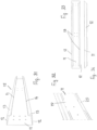
- the connecting piece 24 has a U-shaped cross section with a web 44 ( Fig. 18 and 37 to 39 ), which rests flat against the web 11 of the rail 10 and from whose longitudinal edges two legs 45, 46 protrude vertically. They are, for example, shorter than the web 44 and are spaced from the upper and lower edges 44a, 44b of the web 44.
- the connecting piece 24 is advantageously made in one piece from a metallic material. It is designed such that the cross strut 22 overlaps the connecting piece 24.
- the cross strut 22 has a C-shaped cross-section with a web 47, to whose two longitudinal edges a leg 48, 49 is connected vertically.
- the legs 48, 49 merge into vertically angled edge sections 50, 51 extending towards one another, which are at the same height and are spaced apart from one another over the length of the cross strut 22.
- the cross struts 22 are pushed onto the connecting pieces 24 with their ends in such a way that the edge sections 50, 51 rest on the outside of the leg 45 and the web 47 on the outside of the leg 46 ( Fig. 18d ).
- fastening elements 52 arranged transversely to the cross strut 22, which openings 73, 74 in the edge sections 50, 51 and in the web 47 of the cross struts 22 ( Fig. 36 ) and openings 75 in the legs 45, 46 of the connecting piece 24, the cross struts 22 can be connected easily and reliably to the connecting piece 24.
- the web 44 of the connecting piece 24 also has openings 76 for fastening elements 53, with which the connecting piece 24 is attached to the web 11 of the rail 10.
- the web 11 has corresponding openings.
- the fastening elements 53 can simultaneously fasten the connecting pieces 24 of the two rails 10 to their webs 11.
- the connecting pieces 25 on the longitudinal rails 10 are designed in the same way as the connecting pieces 24.
- the cross struts 22 are attached to the connecting pieces 25 in the same way as previously described for the connecting pieces 24.
- the cross struts 22 are pushed onto the connecting pieces 25 during assembly of the support element 8 and are attached to the longitudinal rails 10 by means of the fastening means 52.
- the connecting pieces 24 of the two rails 10 of the longitudinal stiffener 17 lie next to one another.
- the fastening elements 53 connect the connecting pieces 24 to the rails 10, and these, in turn, are connected to one another.
- Fig. 20 shows a part of a building with the vertical posts 1, between which extend the ceiling 5 and a floor 6. Both the ceiling 5 and the floor 6 are formed by adjacent supporting elements 8 ( Fig. 19 ), which are attached to the posts 1 with the coupling elements 36, as exemplified by the Figs. 12 and 13 has been explained.
- the ceiling 5 is part of a flat roof 54 of the building.
- Various layers are located on and within the supporting elements 8 of the ceiling 5, the arrangement (structure and composition) of which depends on the function of the flat roof 54.
- the upper surface of the flat roof 54 is formed by an upper covering layer 55, which is arranged on a covering layer 56. With an insulating/sealing layer 57 in between, the layers 55, 56 lie on another covering layer 58, which is applied to the supporting elements 8.
- the two covering layers 56, 58 form sealing membranes, which are advantageously bitumen membrane seals.
- a border 59 Adjoining the edge of the ceiling 5 is a border 59, which has a U-shaped cross-section and encloses the uppermost crossbeams 2 of the building.
- the border 59 can consist of an insulating or sealing layer that is suitably secured to the building.
- the border 59 is covered by an approximately U-shaped cover 60, which is suitably secured to the building and is advantageously made of a bent sheet metal.
- the floor 6 is formed by the adjacent support elements 8, which are connected to the posts 1 of the building by means of the coupling elements 36 in the manner described.
- a Floor layer 61 is applied, which can be, for example, impact sound insulation, a screed or a floor covering.
- Fig. 21 shows a building which, in addition to the ceiling 5 and the floor 6, has a further floor 7 which can be designed in the same way as the floor 6.
- the connection of the supporting elements 8 of the floor 7 is carried out with the aid of the coupling elements 36 in the manner described.
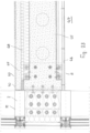
- Fig. 22 shows an enlarged view of the connection of the ceiling 5 to the vertical post 1 of the building.
- the ceiling 5 consists, as described, of the adjacent and firmly connected support elements 8, which are attached to the post 1 with the cross rails 15 and their coupling elements 36 in the manner described.
- the post 1 consists of the stacked and firmly connected post sections 1a, the number of which depends on the height of the building or the posts 1.
- the adjacent posts 1 are connected to each other by the horizontal cross beams 2 ( Fig. 1 ), which together with the post sections delimit fields 4.
- Horizontal frame parts 64 are attached to the outward-facing end faces 63 of the cross members 2, which are used to hold built-in elements 62, in the example case window panes.
- the supporting elements 8 of the ceiling 5 are filled with insulating material, which is covered at the top and bottom by the plate-shaped cover parts 28.
- a plate-shaped ceiling element 66 is attached to the underside of the ceiling 5, completely covering the supporting elements 8.
- the ceiling element 66 rests on the webs 12 of the cross rails 15 and the longitudinal rails 10 and is attached to them.
- the ceiling element 66 it is possible to provide the ceiling element 66 such that it extends across the entire width and length of the ceiling 5, i.e., across all the supporting elements 8 forming the ceiling 5.
- the ceiling elements 66 are connected to the supporting elements 8 in a butt-fitting manner in the manner described.
- the floors 6, 7 are also provided with such a ceiling element 66 on their underside ( Fig. 21 to 23 ).
- the ceiling element 66 is attached to the supporting elements 8 in the same way as the ceiling 5.
- the supporting elements 8 of the floors 6, 7 are provided on their upper side with a corresponding cover 67 ( Fig. 23 ), which can, for example, consist of several layers.
- This cover 67 forms the floor, which can consist of impact sound insulation 68, a screed 69, and a floor covering 70.
- the cover 67 is provided on the support elements 8 such that it advantageously runs flush with the upper side 71 of the associated cross member 2.
- the support elements 8 themselves are filled with the insulating material 65 in the manner described.
- Fig. 24 shows, by way of example, such conduits 72 which are provided at a distance from one another on the cross struts 22 and are located between the cover 67 and the cross struts 22.
- the conduits 72 are suitably attached to the underside of the leg 49 of the cross brace 22.
- the cover 67 is spaced apart from the conduits 72, which are protected from damage by the cover 67.
- the support elements 8 can be very easily attached to the vertical support structure, which is formed, for example, by the posts 1, in the manner described.
- the rails 10, 15, 22 advantageously consist of roll-formed lightweight steel profiles, which can be efficiently assembled and infilled during production to form rigid, quadrangular, preferably rectangular support frames using the connecting pieces 16, 18. This creates a modular lightweight system with simple construction and assembly.
- the supporting elements 8 are connected to each other in the manner described above, ensuring shear resistance, resulting in a tensile structure in the finished state. This forms a stiffening support plate that absorbs all loads, as explained in the introduction.
- the maximum span of the modular lightweight system can be A beam system can be easily expanded as required. This beam system transfers the resulting vertical loads downwards into the foundation via the vertical posts 1.
- the stiffening effect of the tensile structures 5 to 7 ensures that the horizontal deformations of the building - in conjunction with the supporting facade system as a complete static model - are very small.
- Multi-layer panels made of different materials can be used to infill the load-bearing elements and can be attached using simple drilling or sheet metal screws.
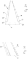
- the Figs. 41 and 42 show two further possibilities for stiffening the supporting elements 8.
- the stiffening is achieved by means of a cross-braced cable bracing 77, which will be referred to as bracing for the sake of simplicity.
- the difference between the two bracings 77 is only that in the embodiment according to Fig. 41 the bracing 77 extends over the entire length of the support element 8, while in the embodiment according to Fig. 42
- the bracing only extends over half the length of the supporting element. Therefore, the supporting element 8 is Fig. 42 provided with two such bracings 77.
- the support element 8 itself is essentially designed according to the described embodiments.
- the cross struts 22 of the supporting element 8 are provided with through-holes 78 through which two cables 79, 80 of the bracing 77 run.
- the two parts 79, 80 cross each other halfway along the length of the supporting element 8.
- the ends of the cables 79, 80 are attached to the corner areas of the supporting element 8.
- a flat holding piece 81 is attached, preferably welded, to the connecting piece 16. It is triangular in shape and is attached to the two legs 16a, 16b. The holding piece 81 extends perpendicular to the legs 16a, 16b and rests flat against the legs with its edges. To ensure secure fastening, the holding piece 81 extends across the entire width of the legs 16a, 16b of the connecting piece 16.
- the holding piece 81 is provided on the connecting piece 16 in such a way that it is spaced from the upper or lower edge of the connecting piece 16.
- the cable 79 is held on the sloping front side 82 of the holding piece 81.
- a U-shaped bracket 86 is attached to the cable end, with both legs 86a, 86b enclosing the holding piece 81.
- the bracket 86 is attached to the holding piece 81 by means of a holding element 84, preferably a retaining bolt.
- the holding element 84 extends through the legs 83a, 83b of the holding element 83 and the holding piece 81.
- the bracket 86 is rotatable about the axis of the holding element 84 so that the cable 79 can be perfectly aligned in the supporting element 8.
- the cables 79, 80 can each consist of a single piece, so that only two cables are required for the bracing 77.
- each cable 79, 80 consists of two cable sections 79a, 79b; 80a, 80b. This allows for easier installation of the bracing 77 in the supporting element 8.
- One end of the cable sections 79a, 79b; 80a, 80b are connected in the manner described above via the holding pieces 81 to the corner connecting pieces 16. Approximately halfway along the length of the supporting element 8, the other ends of the cable sections are connected to holding pieces 85 ( Fig. 43 and 45 ).
- the flat holding piece 85 is suitably attached to one of the connecting pieces 24, with which the cross struts 22 are connected to the longitudinal stiffener 17 in the manner described.
- the cable sections 79a, 79b; 80a, 80b are connected via U-shaped brackets 86, whose legs 86a, 86b engage around the holding piece 85.
- the legs 86a, 86b and the holding piece 85 are penetrated by a holding element 87, which is advantageously a retaining bolt.
- the bracket 86 can be pivoted about the axis of this holding element 87, so that the cable sections can be easily aligned within the support element 8.
- the holding piece 85 serves to connect the two cable sections 79b and 80a.
- the support element 8 can also be provided with two such bracings 77 ( Fig. 42 In this case, a total of four ropes 79, 80 are used, one end of which is in the described in the corner areas of the supporting element 8.
- the other ends of the cables 79, 80 are connected in the area of the connection of the central cross strut 22 with the longitudinal rails 10 of the supporting element 8.
- the connection can be provided in the same way as in the corner areas of the supporting element 8.
- Fig. 46 shows the possibility of designing the rails 10 with non-mirror symmetry in cross-section.
- the upper edge sections 13 of the rail 10 in the installation position of the support element 8 are longer than the lower edge sections 13. Otherwise, the rails 10 are designed identically to the previously described embodiment of the rail 10.
Landscapes
- Engineering & Computer Science (AREA)
- Architecture (AREA)
- Civil Engineering (AREA)
- Structural Engineering (AREA)
- Physics & Mathematics (AREA)
- Electromagnetism (AREA)
- Joining Of Building Structures In Genera (AREA)
Applications Claiming Priority (1)
| Application Number | Priority Date | Filing Date | Title |
|---|---|---|---|
| DE102023004367.2A DE102023004367A1 (de) | 2023-10-27 | 2023-10-27 | Tragelement zur Erstellung von Decken und/oder Böden von Gebäuden |
Publications (1)
| Publication Number | Publication Date |
|---|---|
| EP4545724A1 true EP4545724A1 (fr) | 2025-04-30 |
Family
ID=93258797
Family Applications (1)
| Application Number | Title | Priority Date | Filing Date |
|---|---|---|---|
| EP24208494.5A Pending EP4545724A1 (fr) | 2023-10-27 | 2024-10-23 | Elément de support pour la réalisation de planchers et/ou planchers de bâtiments |
Country Status (2)
| Country | Link |
|---|---|
| EP (1) | EP4545724A1 (fr) |
| DE (1) | DE102023004367A1 (fr) |
Citations (3)
| Publication number | Priority date | Publication date | Assignee | Title |
|---|---|---|---|---|
| DE7909327U1 (de) * | 1979-03-31 | 1979-07-19 | Heinrich Nickel Gmbh, 5240 Betzdorf | Wand- und/oder decken-bauplatte bzw. -paneel |
| AU622263B2 (en) * | 1989-01-19 | 1992-04-02 | Roofing Centre Albury/Wodonga Pty. Ltd., The | Structural framing |
| IT201900001041A1 (it) * | 2019-01-24 | 2020-07-24 | Mauro Pizzolato | Struttura di pannello per costruzioni prefabbricate |
Family Cites Families (4)
| Publication number | Priority date | Publication date | Assignee | Title |
|---|---|---|---|---|
| GB713817A (en) * | 1952-05-28 | 1954-08-18 | Samuel Clipson | Improvements in or relating to the construction of ceilings, wall-coverings and the like |
| DE2752907A1 (de) * | 1977-11-26 | 1979-05-31 | Schmolz & Bickenbach | Plattenelement fuer schallschutzwaende o.dgl. |
| DE3274477D1 (en) * | 1982-06-11 | 1987-01-15 | Egide Jozef Debremaeker | Building |
| DE3440297A1 (de) * | 1984-11-05 | 1986-05-22 | Greschbach, Manfred, 7637 Ettenheim | Plattenfoermiges wandelement |
-
2023
- 2023-10-27 DE DE102023004367.2A patent/DE102023004367A1/de active Pending
-
2024
- 2024-10-23 EP EP24208494.5A patent/EP4545724A1/fr active Pending
Patent Citations (3)
| Publication number | Priority date | Publication date | Assignee | Title |
|---|---|---|---|---|
| DE7909327U1 (de) * | 1979-03-31 | 1979-07-19 | Heinrich Nickel Gmbh, 5240 Betzdorf | Wand- und/oder decken-bauplatte bzw. -paneel |
| AU622263B2 (en) * | 1989-01-19 | 1992-04-02 | Roofing Centre Albury/Wodonga Pty. Ltd., The | Structural framing |
| IT201900001041A1 (it) * | 2019-01-24 | 2020-07-24 | Mauro Pizzolato | Struttura di pannello per costruzioni prefabbricate |
Also Published As
| Publication number | Publication date |
|---|---|
| DE102023004367A1 (de) | 2025-04-30 |
Similar Documents
| Publication | Publication Date | Title |
|---|---|---|
| DE69302390T2 (de) | Rahmen für ein gebäude | |
| DE3303190C2 (de) | Bausatz zur Erstellung mobiler Bauten, insbesondere für Messe- und Ausstellungsbauten | |
| EP0385923B1 (fr) | Elément de construction pour la construction de bâtiments, parties de bâtiments ou similaire | |
| DE3128165A1 (de) | Schalldaemmendes wandbausystem fuer industriebauten, sowie kassettenprofil hierfuer | |
| EP0843053A1 (fr) | Accouplement par friction entre poteaux et poutres ou entre poutres | |
| DE3824387C2 (fr) | ||
| WO2014060155A1 (fr) | Système de bâtiment, en particulier bâtiment résidentiel | |
| AT511169A1 (de) | Modulares gebäude | |
| DE9409626U1 (de) | Balkonkonstruktion | |
| EP4545724A1 (fr) | Elément de support pour la réalisation de planchers et/ou planchers de bâtiments | |
| DE4000956C2 (de) | Element für den Großtafelbau aus Beton | |
| EP1270833A2 (fr) | Elément de construction pour l'isolation thermique | |
| DE60315714T2 (de) | Modularbauelement und verfahren zu seiner montage | |
| DE2336482A1 (de) | Raumzelle fuer gebaeude | |
| DE202019102611U1 (de) | Trockenbau-Wandsystem | |
| DE20305659U1 (de) | Ständerbauwerk, insbesondere aufgeständerter Vorsatzbalkon | |
| DE2750931C2 (fr) | ||
| DE1559436C (de) | Versetzbare Trennwand mit einem Traggerippe und Wandfüllungen | |
| EP4464851A2 (fr) | Bâtiment | |
| EP4455417A1 (fr) | Système modulaire pour la fabrication de structures modulaires | |
| DE202016105596U1 (de) | Tragwerk und Gebäude | |
| DE202017001504U1 (de) | Leichtbauwand, insbesondere zur Erstellung einer Trennwand in Räumen von Bauwerken | |
| AT4552U2 (de) | Dachelement, bauwerk und verfahren zum herstellen eines derartigen bauwerkes | |
| EP4194613A1 (fr) | Module de fabrication d'une fondation en béton, utilisation et procédé | |
| AT277533B (de) | Gebäudeskelett und Verfahren zu seiner Errichtung |
Legal Events
| Date | Code | Title | Description |
|---|---|---|---|
| PUAI | Public reference made under article 153(3) epc to a published international application that has entered the european phase |
Free format text: ORIGINAL CODE: 0009012 |
|
| STAA | Information on the status of an ep patent application or granted ep patent |
Free format text: STATUS: THE APPLICATION HAS BEEN PUBLISHED |
|
| AK | Designated contracting states |
Kind code of ref document: A1 Designated state(s): AL AT BE BG CH CY CZ DE DK EE ES FI FR GB GR HR HU IE IS IT LI LT LU LV MC ME MK MT NL NO PL PT RO RS SE SI SK SM TR |
|
| STAA | Information on the status of an ep patent application or granted ep patent |
Free format text: STATUS: REQUEST FOR EXAMINATION WAS MADE |
|
| 17P | Request for examination filed |
Effective date: 20251030 |