EP4545767A1 - Verfahren zum betreiben einer turbomaschine, turbomaschine und verfahren zur herstellung - Google Patents
Verfahren zum betreiben einer turbomaschine, turbomaschine und verfahren zur herstellung Download PDFInfo
- Publication number
- EP4545767A1 EP4545767A1 EP23315399.8A EP23315399A EP4545767A1 EP 4545767 A1 EP4545767 A1 EP 4545767A1 EP 23315399 A EP23315399 A EP 23315399A EP 4545767 A1 EP4545767 A1 EP 4545767A1
- Authority
- EP
- European Patent Office
- Prior art keywords
- shaft
- turbo machine
- impeller
- bearing
- thermal insulation
- Prior art date
- Legal status (The legal status is an assumption and is not a legal conclusion. Google has not performed a legal analysis and makes no representation as to the accuracy of the status listed.)
- Withdrawn
Links
Images


Classifications
-
- F—MECHANICAL ENGINEERING; LIGHTING; HEATING; WEAPONS; BLASTING
- F02—COMBUSTION ENGINES; HOT-GAS OR COMBUSTION-PRODUCT ENGINE PLANTS
- F02C—GAS-TURBINE PLANTS; AIR INTAKES FOR JET-PROPULSION PLANTS; CONTROLLING FUEL SUPPLY IN AIR-BREATHING JET-PROPULSION PLANTS
- F02C7/00—Features, components parts, details or accessories, not provided for in, or of interest apart form groups F02C1/00 - F02C6/00; Air intakes for jet-propulsion plants
- F02C7/22—Fuel supply systems
-
- F—MECHANICAL ENGINEERING; LIGHTING; HEATING; WEAPONS; BLASTING
- F01—MACHINES OR ENGINES IN GENERAL; ENGINE PLANTS IN GENERAL; STEAM ENGINES
- F01D—NON-POSITIVE DISPLACEMENT MACHINES OR ENGINES, e.g. STEAM TURBINES
- F01D11/00—Preventing or minimising internal leakage of working-fluid, e.g. between stages
- F01D11/02—Preventing or minimising internal leakage of working-fluid, e.g. between stages by non-contact sealings, e.g. of labyrinth type
- F01D11/04—Preventing or minimising internal leakage of working-fluid, e.g. between stages by non-contact sealings, e.g. of labyrinth type using sealing fluid, e.g. steam
-
- F—MECHANICAL ENGINEERING; LIGHTING; HEATING; WEAPONS; BLASTING
- F01—MACHINES OR ENGINES IN GENERAL; ENGINE PLANTS IN GENERAL; STEAM ENGINES
- F01D—NON-POSITIVE DISPLACEMENT MACHINES OR ENGINES, e.g. STEAM TURBINES
- F01D25/00—Component parts, details, or accessories, not provided for in, or of interest apart from, other groups
- F01D25/16—Arrangement of bearings; Supporting or mounting bearings in casings
-
- F—MECHANICAL ENGINEERING; LIGHTING; HEATING; WEAPONS; BLASTING
- F01—MACHINES OR ENGINES IN GENERAL; ENGINE PLANTS IN GENERAL; STEAM ENGINES
- F01D—NON-POSITIVE DISPLACEMENT MACHINES OR ENGINES, e.g. STEAM TURBINES
- F01D25/00—Component parts, details, or accessories, not provided for in, or of interest apart from, other groups
- F01D25/18—Lubricating arrangements
- F01D25/183—Sealing means
-
- F—MECHANICAL ENGINEERING; LIGHTING; HEATING; WEAPONS; BLASTING
- F02—COMBUSTION ENGINES; HOT-GAS OR COMBUSTION-PRODUCT ENGINE PLANTS
- F02C—GAS-TURBINE PLANTS; AIR INTAKES FOR JET-PROPULSION PLANTS; CONTROLLING FUEL SUPPLY IN AIR-BREATHING JET-PROPULSION PLANTS
- F02C1/00—Gas-turbine plants characterised by the use of hot gases or unheated pressurised gases, as the working fluid
- F02C1/02—Gas-turbine plants characterised by the use of hot gases or unheated pressurised gases, as the working fluid the working fluid being an unheated pressurised gas
-
- F—MECHANICAL ENGINEERING; LIGHTING; HEATING; WEAPONS; BLASTING
- F02—COMBUSTION ENGINES; HOT-GAS OR COMBUSTION-PRODUCT ENGINE PLANTS
- F02C—GAS-TURBINE PLANTS; AIR INTAKES FOR JET-PROPULSION PLANTS; CONTROLLING FUEL SUPPLY IN AIR-BREATHING JET-PROPULSION PLANTS
- F02C3/00—Gas-turbine plants characterised by the use of combustion products as the working fluid
- F02C3/20—Gas-turbine plants characterised by the use of combustion products as the working fluid using a special fuel, oxidant, or dilution fluid to generate the combustion products
- F02C3/22—Gas-turbine plants characterised by the use of combustion products as the working fluid using a special fuel, oxidant, or dilution fluid to generate the combustion products the fuel or oxidant being gaseous at standard temperature and pressure
-
- F—MECHANICAL ENGINEERING; LIGHTING; HEATING; WEAPONS; BLASTING
- F02—COMBUSTION ENGINES; HOT-GAS OR COMBUSTION-PRODUCT ENGINE PLANTS
- F02C—GAS-TURBINE PLANTS; AIR INTAKES FOR JET-PROPULSION PLANTS; CONTROLLING FUEL SUPPLY IN AIR-BREATHING JET-PROPULSION PLANTS
- F02C7/00—Features, components parts, details or accessories, not provided for in, or of interest apart form groups F02C1/00 - F02C6/00; Air intakes for jet-propulsion plants
- F02C7/06—Arrangements of bearings; Lubricating
-
- F—MECHANICAL ENGINEERING; LIGHTING; HEATING; WEAPONS; BLASTING
- F02—COMBUSTION ENGINES; HOT-GAS OR COMBUSTION-PRODUCT ENGINE PLANTS
- F02C—GAS-TURBINE PLANTS; AIR INTAKES FOR JET-PROPULSION PLANTS; CONTROLLING FUEL SUPPLY IN AIR-BREATHING JET-PROPULSION PLANTS
- F02C7/00—Features, components parts, details or accessories, not provided for in, or of interest apart form groups F02C1/00 - F02C6/00; Air intakes for jet-propulsion plants
- F02C7/24—Heat or noise insulation
-
- F—MECHANICAL ENGINEERING; LIGHTING; HEATING; WEAPONS; BLASTING
- F02—COMBUSTION ENGINES; HOT-GAS OR COMBUSTION-PRODUCT ENGINE PLANTS
- F02C—GAS-TURBINE PLANTS; AIR INTAKES FOR JET-PROPULSION PLANTS; CONTROLLING FUEL SUPPLY IN AIR-BREATHING JET-PROPULSION PLANTS
- F02C7/00—Features, components parts, details or accessories, not provided for in, or of interest apart form groups F02C1/00 - F02C6/00; Air intakes for jet-propulsion plants
- F02C7/28—Arrangement of seals
-
- F—MECHANICAL ENGINEERING; LIGHTING; HEATING; WEAPONS; BLASTING
- F04—POSITIVE - DISPLACEMENT MACHINES FOR LIQUIDS; PUMPS FOR LIQUIDS OR ELASTIC FLUIDS
- F04D—NON-POSITIVE-DISPLACEMENT PUMPS
- F04D29/00—Details, component parts, or accessories
- F04D29/08—Sealings
- F04D29/10—Shaft sealings
- F04D29/12—Shaft sealings using sealing-rings
- F04D29/122—Shaft sealings using sealing-rings especially adapted for elastic fluid pumps
- F04D29/124—Shaft sealings using sealing-rings especially adapted for elastic fluid pumps with special means for adducting cooling or sealing fluid
-
- F—MECHANICAL ENGINEERING; LIGHTING; HEATING; WEAPONS; BLASTING
- F05—INDEXING SCHEMES RELATING TO ENGINES OR PUMPS IN VARIOUS SUBCLASSES OF CLASSES F01-F04
- F05D—INDEXING SCHEME FOR ASPECTS RELATING TO NON-POSITIVE-DISPLACEMENT MACHINES OR ENGINES, GAS-TURBINES OR JET-PROPULSION PLANTS
- F05D2240/00—Components
- F05D2240/55—Seals
Definitions
- the present invention relates to a method for operating a turbo machine, e.g., a cryogenic turbo machine, with an impeller mounted on a shaft, such turbo machine and to a method of manufacturing such turbo machine.
- a turbo machine e.g., a cryogenic turbo machine
- an impeller mounted on a shaft such turbo machine and to a method of manufacturing such turbo machine.
- Turbo machines can be used in different applications.
- cryogenic applications i.e. applications with process gases at cryogenic temperatures, e.g., plants for air separation or the like
- cryogenic turbo machines like turbo expanders and/or compressors are often used.
- Such turbo machines typically comprise an expander impeller and/or a compressor impeller, which are fixed on a shaft.
- Such turbo machines typically also comprise an inlet or inlet channel configured to guide operating fluid, e.g., gas like the mentioned process gas, to such impeller, and an outlet or outlet channel configured to guide said operating fluid, e.g., after expansion, from that impeller, e.g., to the outside.
- operating fluid e.g., gas like the mentioned process gas
- outlet or outlet channel configured to guide said operating fluid, e.g., after expansion, from that impeller, e.g., to the outside.
- the impeller of the turbo machine and a corresponding impeller-sided bearing part are subject to very cold temperatures
- the shaft, its bearing and a corresponding bearing carrier are typically subject to ambient or at least warmer temperatures; bearings, e.g. can even be warmer than ambient temperature. This can lead to massive heat input from the cold to the warm parts, depending on the specific temperatures. It is therefore an object of the present invention to provide an improved turbo machine.
- turbo machines in particular cryogenic turbo machines, like turbo compressors or turbo expanders with an impeller arranged or mounted on a shaft, and to operating such turbo machines.
- Types of turbomachines are, for example, centrifugal turbo machines and radial turbo machines.
- Such a turbo machine comprises an impeller, a bearing, and a shaft.
- such turbo machine can also comprise an impeller-sided bearing part and a bearing carrier. Said impeller is arranged on said shaft and said impeller can, at least partly, be closed by said impeller-sided bearing part.
- said shaft is supported by said bearing and said bearing can be supported in and, at least partly, enclosed by said bearing carrier.
- such a turbo machine typically comprises an inlet (or inlet channel) configured to guide operating fluid, e.g., from an inlet opening, to said impeller, and an outlet or outlet channel configured to guide operating fluid from said impeller, e.g., to an outlet opening.
- Cryogenic turbo machines are used with operating fluid like gases or process gases (or fluids or process fluids) at cryogenic temperatures, i.e., very low temperatures of, e.g., less than -100°C or even down to -230°C or -250°C at the expander outlet or at the compressor inlet. Depending on the kind of turbo machine, such gases are compressed and/or expanded. Turbo machines in other applications can also be used with operating fluids at higher temperatures.
- the impeller-sided bearing part (enclosing the expansion impeller) can be connected to the bearing carrier or also formed with it from a single piece.
- the cold power can be extracted through a compressor impeller or through a generator connected to or arranged on said shaft.
- Such generator can, for example, also be connected via a gear box.
- the cold power could, e.g., also be extracted via a brake in such a radial turbo machine, the fluid is expanded from high-pressure level to low pressure level. This expansion produces a high difference of temperature between the inlet (high-pressure area) and the outlet (low-pressure area).
- Typical values for hydrogen gas as operating fluid are, for example, an inlet temperature of -230°C and an outlet temperature at - 245°C, leading to a very low temperature in the expander impeller-sided bearing part.
- Such heat input can be reduced by providing the turbo machine with a dry gas seal configured to seal the shaft, and/or when the shaft is configured as a hollow shaft.
- a hollow shaft comprises, for example, an inside and, e.g., enclosed, space free of solid material.
- the hollow shaft allows to reduce the cold transfer through the shaft and avoiding hydrogen (or other operating fluid) leakages from the high-pressure part to the low-pressure part (the bearing carrier). This also allows to minimize the heat intakes from the warm bearing carrier side to the cryogenic (expander) side.
- the dry gas seal allows the tightening between the cryogenic part and the bearing or bearing carrier, even in case of gas barrier malfunction.
- the dry gas seal can be of different types of technology, e.g., single or tandem type, and with or without carbon rings or others.
- cryogenic fluid like hydrogen or others, at a temperature of below -180°C or even below -200°C, can be processed by operating such turbo machine.
- Such cryogenic fluid is, thus, used as process fluid being compressed and/or expanded by means of the turbo machine.
- Each of the hollow shaft and the dry gas seal allows sufficient isolation for these low temperatures.
- the turbo machine further comprises a thermal insulation component, wherein the thermal insulation component is arranged between the impeller and the dry gas seal.
- the thermal insulation component is configured as a thermal insulation.
- Such thermal insulation plate can have an opening (i.e., the thermal insulation plate has the form of a ring or an annular shape), wherein the said shaft is arranged to protrude through said opening.
- One or more air gaps can be provided with the thermal insulation component or thermal insulation component.
- a thermal insulation located in front of the dry gas seal allows to maintain a less cold temperature at the level of the dry gas.
- Such thermal insulation ring allows also to reduce the cold transfer migration from a pressurized hydrogen part to the bearing or bearing carrier.
- the bearing carrier can be equipped with oil bearings, roller bearings, gas bearings or magnetic bearings; depending on the type of bearing, the bearing carrier can be formed or configured correspondingly.
- This invention is applicable for cryogenic rotating machines, like radial cryogenic expanders connected to an oil break or to a generator, turboexpanders, centrifugal compressors, axial turbines.
- the invention is particularly applicable where there is need to have a DGS (Dry Gas Seal) sealing technology compatible with low operating temperatures, e.g., between -200 to -272°C.
- DGS Dry Gas Seal
- cryogenic fluid preferably, hydrogen
- a temperature of below -180°C or -200°C is advantageous. That is applicable for cryogenic gases like hydrogen but can also be used for other cryogenic gases like helium or others, usually operating between -200°C and -270°C.
- Fig. 1 schematically illustrates a turbo machine 100 according to an embodiment of the invention.
- the turbo machine 100 e.g., a cryogenic turbo machine is, by means of example, configured as a compressor and an expander, i.e., both are combined in one turbo machine.
- Turbo machine 100 comprises, hence, two impellers, an impeller 110 and an impeller 120, both mounted on a shaft 130.
- the turbo machine 100 comprises channels 112 and 114 on the side of the impeller 110, the channels used respectively as inlet channel and outlet channel for the operating fluid to be compressed.
- the turbo machine 100 further comprises channels 122 and 124 on the side of the impeller 120, the channels used respectively as inlet channel and outlet channel for the operating fluid to be expanded.
- the impeller 110 is a compressor impeller and the impeller 120 is an expander impeller.
- the operating fluid to be compressed and the operating fluid to be expanded can have identical or can have different properties like pressure, temperature, chemical composition etc.
- a turbo machine could also have only one impeller mounted on one end of shaft and an electric machine, e.g., a generator or alternator, mounted on the other end of the shaft.
- an electric machine e.g., a generator or alternator
- the turbo machine 100 comprises a bearing 140 and, e.g., further bearing 142, for supporting said shaft 130.
- bearing 140 is provided on the side of the impeller 110, and bearing 142 is provided on the side of the impeller 120.
- the turbo machine 100 comprises an impeller-sided bearing part 150 and a bearing carrier 154.
- the impeller-sided bearing part 150 encloses impeller 110 at least partly.
- Another impeller-sided bearing part 152 can enclose impeller 120 at least party.
- the bearing carrier 154 supports said bearing 140 and, e.g., also bearing 142. in addition, said bearing carrier 154 also encloses, at least partly, said bearing 140 and, e.g., also bearing 142.
- the impeller-sided bearing part 150 and the bearing carrier 154 are illustrated only very schematically in Fig. 1 . More detailed views are shown in Fig. 2 and Fig. 3 .
- the shaft 130 is configured as a hollow shaft; this is not visible in Fig. 1 but in Fig. 2 .
- the turbo machine 100 comprises a dry gas seal 170 and a thermal insulation component 180, e.g., a thermal insulation plate.
- the dry gas seal 170 is configured to seal the shaft 130, i.e., the dry gas seal allows the tightening between the cryogenic part on the side of the impeller 110 and the bearing 140 or bearing carrier 154, even in case of gas barrier malfunction. More detailed views of the dry gas seal are shown in Fig. 2 and Fig. 4 .
- the thermal insulation component or plate 180 is arranged between the impeller 110 and the dry gas seal 170.
- the thermal insulation plate 180 has, by means of example, an opening (i.e., the thermal insulation plate has the form of a ring or an annular shape), wherein the said shaft 130 is arranged to protrude through said opening.
- Such thermal insulation located in front of the dry gas seal 170 allows to maintain a less cold temperature at the level of the dry gas.
- Such thermal insulation ring allows also to reduce the cold transfer migration from a pressurized hydrogen part to the bearing or bearing carrier.
- Fig. 2 shows parts of the turbomachine 100 in more detail; in particular, the impeller-sided bearing part 150 and the bearing carrier 154 are shown, in addition to the shaft 130, the impeller 110 and the bearing 140. A rotation axis R is shown for better understanding.
- Fig. 3 shows also parts of the turbomachine 100 in more detail and in a perspective view; in particular, the impeller-sided bearing part 150 and the bearing carrier 154 are shown.
- the rotation axis R is also shown for better understanding.
- the turbo machine further comprises by means of example, as shown in Figs. 2 and 3 , several connecting structures 160, which are, for example, rod shaped; only one of these connecting structures 160 is visible in the cross-section of Fig. 2 , but several of them are visible in Fig. 3 .
- these connecting structures 160 connecting structures are spaced apart from each other and arranged annularly around the shaft 130 as can be seen in Fig. 3 (the shaft itself is not shown in Fig. 3 ).
- the impeller-sided bearing part 150 and the bearing carrier 154 are, as can be seen in Figs. 2 and 3 , spatially spaced apart from each other (seen along the rotational axis R) and connected to each other by connecting structures 160.
- the impeller-sided bearing part 160, the bearing carrier 155 and the connecting structures 160 can, for example, form parts of a component made of a single piece, i.e., these parts can be provided integrally.
- the dry gas seal 170 is located around the shaft 130, inside the impeller-sided bearing part 150 and arranged next to the bearing 140 and the bearing carrier 154.
- the dry gas seal 170 can be configured as a cartridge that can be inserted into the impeller-sided bearing part 150, for example.
- Several sealings like O-rings can be provided to seal the cartridge against the impeller-sided bearing part 150.
- the thermal insulation plate 180 has an opening 182, wherein the said shaft 130 is arranged to protrude through said opening 182.
- Thermal insulation plate 180 is arranged between the impeller 110 and the dry gas seal 170 (or the dry gas seal cartridge).
- the shaft 130 is, as explained above, configured as a hollow shaft, i.e., the shaft comprises a, space 132 free of solid material in its inside.
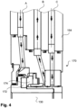
- Fig. 4 illustrates the dry gas seal 170 in more detail. Besides the dry gas seal 170, part of the shaft 130 at the lower end of Fig. 4 and part of the impeller-sided bearing part 154 in the upper part of Fig. 4 are shown. Two parts of the dry gas seal 170 are, among others, part 172 which is rotating with the shaft 130, and part 174 which is not rotating but stationary. Further, three channels A, B, C are illustrated which are used for a gas injection and/or connection. A flow of gas is indicated by means of arrows. These channels A, B, C are provided in the dry gas seal 170 itself and in the impeller-sided bearing part 154.
- Channel A is used for injection of clean and dry process gas, e.g., cryogenic process gas, e.g., hydrogen, for which cryogenic process the turbomachine is used to process.
- This cryogenic process gas is provided at the side of the impeller 110.
- Channel C is used for injection of separation gas, e.g., nitrogen.
- Channel B is a connection to the flare or to a safe area and is used for mixing of the separation gas and the process gas.
- This type of dry gas seal is a single arrangement with a tertiary seal and allows sufficient sealing. It is noted that a single dry gas seal is sometimes not sufficient for hydrogen but can, e.g., be used in case of rotor dynamic issues with specific protection. As mentioned above, other types of dry gas seals can be used.
- Fig. 5 illustrates, by means of a flow diagram, a manufacturing method according to an embodiment of the invention.
- the method is for manufacturing a turbo machine as, e.g., shown in Figs. 1 to 4 .
- Such turbo machine comprises an impeller, a bearing and a shaft. Said impeller is arranged on said shaft and said shaft is supported by said bearing.
- the method comprises, in a step 500, providing a dry gas seal to the shaft.
- a dry gas seal to the shaft.
- This can be in the form of a cartridge, for example.
- the shaft is provided as a hollow shaft.
- a thermal insulation component in particular, a thermal insulation plate, can be provided. Said thermal insulation component is arranged between the impeller and the dry gas seal. It is mentioned that each step 500, 510, 520 can be used independently from the others.
Landscapes
- Engineering & Computer Science (AREA)
- Chemical & Material Sciences (AREA)
- Combustion & Propulsion (AREA)
- Mechanical Engineering (AREA)
- General Engineering & Computer Science (AREA)
- Structures Of Non-Positive Displacement Pumps (AREA)
Priority Applications (2)
| Application Number | Priority Date | Filing Date | Title |
|---|---|---|---|
| EP23315399.8A EP4545767A1 (de) | 2023-10-26 | 2023-10-26 | Verfahren zum betreiben einer turbomaschine, turbomaschine und verfahren zur herstellung |
| PCT/EP2024/025297 WO2025087556A1 (en) | 2023-10-26 | 2024-10-10 | Method for operating a turbo machine, turbo machine and method of manufacturing |
Applications Claiming Priority (1)
| Application Number | Priority Date | Filing Date | Title |
|---|---|---|---|
| EP23315399.8A EP4545767A1 (de) | 2023-10-26 | 2023-10-26 | Verfahren zum betreiben einer turbomaschine, turbomaschine und verfahren zur herstellung |
Publications (1)
| Publication Number | Publication Date |
|---|---|
| EP4545767A1 true EP4545767A1 (de) | 2025-04-30 |
Family
ID=88833678
Family Applications (1)
| Application Number | Title | Priority Date | Filing Date |
|---|---|---|---|
| EP23315399.8A Withdrawn EP4545767A1 (de) | 2023-10-26 | 2023-10-26 | Verfahren zum betreiben einer turbomaschine, turbomaschine und verfahren zur herstellung |
Country Status (2)
| Country | Link |
|---|---|
| EP (1) | EP4545767A1 (de) |
| WO (1) | WO2025087556A1 (de) |
Citations (3)
| Publication number | Priority date | Publication date | Assignee | Title |
|---|---|---|---|---|
| US20180347589A1 (en) * | 2015-11-13 | 2018-12-06 | Mitsubishi Heavy Industries, Ltd. | Centrifugal compressor |
| CN115341961A (zh) * | 2022-07-04 | 2022-11-15 | 昆明理工大学 | 一种氢气液化低温透平膨胀机用干气密封装置、装配方法 |
| AU2019440859B2 (en) * | 2019-04-17 | 2023-04-27 | Institute Of High Energy Physics, Chinese Academy Of Sciences | Vertical cryogenic liquid centrifugal pump |
Family Cites Families (1)
| Publication number | Priority date | Publication date | Assignee | Title |
|---|---|---|---|---|
| CN218062404U (zh) * | 2022-10-14 | 2022-12-16 | 四川空分设备(集团)有限责任公司 | 一种叶轮主轴联接机构 |
-
2023
- 2023-10-26 EP EP23315399.8A patent/EP4545767A1/de not_active Withdrawn
-
2024
- 2024-10-10 WO PCT/EP2024/025297 patent/WO2025087556A1/en active Pending
Patent Citations (3)
| Publication number | Priority date | Publication date | Assignee | Title |
|---|---|---|---|---|
| US20180347589A1 (en) * | 2015-11-13 | 2018-12-06 | Mitsubishi Heavy Industries, Ltd. | Centrifugal compressor |
| AU2019440859B2 (en) * | 2019-04-17 | 2023-04-27 | Institute Of High Energy Physics, Chinese Academy Of Sciences | Vertical cryogenic liquid centrifugal pump |
| CN115341961A (zh) * | 2022-07-04 | 2022-11-15 | 昆明理工大学 | 一种氢气液化低温透平膨胀机用干气密封装置、装配方法 |
Also Published As
| Publication number | Publication date |
|---|---|
| WO2025087556A1 (en) | 2025-05-01 |
Similar Documents
| Publication | Publication Date | Title |
|---|---|---|
| US3647311A (en) | Turbine interstage seal assembly | |
| EP2474762B1 (de) | Elliptisches Abdichtsystem | |
| US2445661A (en) | Axial flow turbine, compressor and the like | |
| US9347459B2 (en) | Abradable seal with axial offset | |
| US4573867A (en) | Housing for turbomachine rotors | |
| RU2565649C2 (ru) | Многоступенчатый компрессор, способ изготовления компрессора и ротационная установка | |
| US9759083B2 (en) | Cryogenic liquid expansion turbine | |
| EP2737179B1 (de) | Zentrifugallaufrad und turbomaschine | |
| US10344608B2 (en) | Seal arrangement in a turbine and method for confining the operating fluid | |
| EP2930370A1 (de) | Zentrifugalverdichter, lader damit und verfahren zum betrieb des zentrifugalverdichters | |
| US8147185B2 (en) | Systems, methods, and apparatus for controlling gas leakage in a turbine | |
| US20180328210A1 (en) | Super-Critical C02 Expander | |
| KR102733421B1 (ko) | 다단 터보기계 | |
| US20180223869A1 (en) | Turbomachine and method of operating a turbomachine | |
| EP4545767A1 (de) | Verfahren zum betreiben einer turbomaschine, turbomaschine und verfahren zur herstellung | |
| US5456577A (en) | Centrifugal pump with resiliently biasing diffuser | |
| US20130272872A1 (en) | Shaft sealing system for steam turbines | |
| KR20030047827A (ko) | 분리 구조체 | |
| US2966296A (en) | Gas-turbine engines with load balancing means | |
| CN121941835A (zh) | 用于操作涡轮机的方法、涡轮机和制造方法 | |
| US20250364871A1 (en) | Integral expander generator for hydrogen applications with magnetic bearings | |
| EP4553322A1 (de) | Turbomaschine und verfahren zur herstellung | |
| US3202341A (en) | Turbomachines assembly | |
| US3201941A (en) | Assembly of turbomachines | |
| US20130270775A1 (en) | Shaft sealing system for steam turbines |
Legal Events
| Date | Code | Title | Description |
|---|---|---|---|
| PUAI | Public reference made under article 153(3) epc to a published international application that has entered the european phase |
Free format text: ORIGINAL CODE: 0009012 |
|
| STAA | Information on the status of an ep patent application or granted ep patent |
Free format text: STATUS: THE APPLICATION HAS BEEN PUBLISHED |
|
| AK | Designated contracting states |
Kind code of ref document: A1 Designated state(s): AL AT BE BG CH CY CZ DE DK EE ES FI FR GB GR HR HU IE IS IT LI LT LU LV MC ME MK MT NL NO PL PT RO RS SE SI SK SM TR |
|
| STAA | Information on the status of an ep patent application or granted ep patent |
Free format text: STATUS: THE APPLICATION IS DEEMED TO BE WITHDRAWN |
|
| 18D | Application deemed to be withdrawn |
Effective date: 20251031 |