EP4545814A1 - Mécanisme d'arbre rotatif et dispositif électronique - Google Patents
Mécanisme d'arbre rotatif et dispositif électronique Download PDFInfo
- Publication number
- EP4545814A1 EP4545814A1 EP23909372.7A EP23909372A EP4545814A1 EP 4545814 A1 EP4545814 A1 EP 4545814A1 EP 23909372 A EP23909372 A EP 23909372A EP 4545814 A1 EP4545814 A1 EP 4545814A1
- Authority
- EP
- European Patent Office
- Prior art keywords
- arc
- rotation
- hinge mechanism
- groove
- support arm
- Prior art date
- Legal status (The legal status is an assumption and is not a legal conclusion. Google has not performed a legal analysis and makes no representation as to the accuracy of the status listed.)
- Pending
Links
Images



Classifications
-
- H—ELECTRICITY
- H05—ELECTRIC TECHNIQUES NOT OTHERWISE PROVIDED FOR
- H05K—PRINTED CIRCUITS; CASINGS OR CONSTRUCTIONAL DETAILS OF ELECTRIC APPARATUS; MANUFACTURE OF ASSEMBLAGES OF ELECTRICAL COMPONENTS
- H05K5/00—Casings, cabinets or drawers for electric apparatus
- H05K5/02—Details
- H05K5/0217—Mechanical details of casings
- H05K5/0226—Hinges
-
- G—PHYSICS
- G06—COMPUTING OR CALCULATING; COUNTING
- G06F—ELECTRIC DIGITAL DATA PROCESSING
- G06F1/00—Details not covered by groups G06F3/00 - G06F13/00 and G06F21/00
- G06F1/16—Constructional details or arrangements
- G06F1/1613—Constructional details or arrangements for portable computers
- G06F1/1633—Constructional details or arrangements of portable computers not specific to the type of enclosures covered by groups G06F1/1615 - G06F1/1626
- G06F1/1675—Miscellaneous details related to the relative movement between the different enclosures or enclosure parts
- G06F1/1681—Details related solely to hinges
-
- F—MECHANICAL ENGINEERING; LIGHTING; HEATING; WEAPONS; BLASTING
- F16—ENGINEERING ELEMENTS AND UNITS; GENERAL MEASURES FOR PRODUCING AND MAINTAINING EFFECTIVE FUNCTIONING OF MACHINES OR INSTALLATIONS; THERMAL INSULATION IN GENERAL
- F16C—SHAFTS; FLEXIBLE SHAFTS; ELEMENTS OR CRANKSHAFT MECHANISMS; ROTARY BODIES OTHER THAN GEARING ELEMENTS; BEARINGS
- F16C11/00—Pivots; Pivotal connections
- F16C11/04—Pivotal connections
-
- F—MECHANICAL ENGINEERING; LIGHTING; HEATING; WEAPONS; BLASTING
- F16—ENGINEERING ELEMENTS AND UNITS; GENERAL MEASURES FOR PRODUCING AND MAINTAINING EFFECTIVE FUNCTIONING OF MACHINES OR INSTALLATIONS; THERMAL INSULATION IN GENERAL
- F16C—SHAFTS; FLEXIBLE SHAFTS; ELEMENTS OR CRANKSHAFT MECHANISMS; ROTARY BODIES OTHER THAN GEARING ELEMENTS; BEARINGS
- F16C11/00—Pivots; Pivotal connections
- F16C11/04—Pivotal connections
- F16C11/10—Arrangements for locking
-
- F—MECHANICAL ENGINEERING; LIGHTING; HEATING; WEAPONS; BLASTING
- F16—ENGINEERING ELEMENTS AND UNITS; GENERAL MEASURES FOR PRODUCING AND MAINTAINING EFFECTIVE FUNCTIONING OF MACHINES OR INSTALLATIONS; THERMAL INSULATION IN GENERAL
- F16C—SHAFTS; FLEXIBLE SHAFTS; ELEMENTS OR CRANKSHAFT MECHANISMS; ROTARY BODIES OTHER THAN GEARING ELEMENTS; BEARINGS
- F16C11/00—Pivots; Pivotal connections
- F16C11/04—Pivotal connections
- F16C11/12—Pivotal connections incorporating flexible connections, e.g. leaf springs
-
- G—PHYSICS
- G06—COMPUTING OR CALCULATING; COUNTING
- G06F—ELECTRIC DIGITAL DATA PROCESSING
- G06F1/00—Details not covered by groups G06F3/00 - G06F13/00 and G06F21/00
- G06F1/16—Constructional details or arrangements
-
- G—PHYSICS
- G06—COMPUTING OR CALCULATING; COUNTING
- G06F—ELECTRIC DIGITAL DATA PROCESSING
- G06F1/00—Details not covered by groups G06F3/00 - G06F13/00 and G06F21/00
- G06F1/16—Constructional details or arrangements
- G06F1/1613—Constructional details or arrangements for portable computers
- G06F1/1615—Constructional details or arrangements for portable computers with several enclosures having relative motions, each enclosure supporting at least one I/O or computing function
- G06F1/1616—Constructional details or arrangements for portable computers with several enclosures having relative motions, each enclosure supporting at least one I/O or computing function with folding flat displays, e.g. laptop computers or notebooks having a clamshell configuration, with body parts pivoting to an open position around an axis parallel to the plane they define in closed position
-
- G—PHYSICS
- G06—COMPUTING OR CALCULATING; COUNTING
- G06F—ELECTRIC DIGITAL DATA PROCESSING
- G06F1/00—Details not covered by groups G06F3/00 - G06F13/00 and G06F21/00
- G06F1/16—Constructional details or arrangements
- G06F1/1613—Constructional details or arrangements for portable computers
- G06F1/1633—Constructional details or arrangements of portable computers not specific to the type of enclosures covered by groups G06F1/1615 - G06F1/1626
- G06F1/1637—Details related to the display arrangement, including those related to the mounting of the display in the housing
- G06F1/1652—Details related to the display arrangement, including those related to the mounting of the display in the housing the display being flexible, e.g. mimicking a sheet of paper, or rollable
-
- G—PHYSICS
- G09—EDUCATION; CRYPTOGRAPHY; DISPLAY; ADVERTISING; SEALS
- G09F—DISPLAYING; ADVERTISING; SIGNS; LABELS OR NAME-PLATES; SEALS
- G09F9/00—Indicating arrangements for variable information in which the information is built-up on a support by selection or combination of individual elements
- G09F9/30—Indicating arrangements for variable information in which the information is built-up on a support by selection or combination of individual elements in which the desired character or characters are formed by combining individual elements
- G09F9/301—Indicating arrangements for variable information in which the information is built-up on a support by selection or combination of individual elements in which the desired character or characters are formed by combining individual elements flexible foldable or roll-able electronic displays, e.g. thin LCD, OLED
-
- H—ELECTRICITY
- H04—ELECTRIC COMMUNICATION TECHNIQUE
- H04M—TELEPHONIC COMMUNICATION
- H04M1/00—Substation equipment, e.g. for use by subscribers
- H04M1/02—Constructional features of telephone sets
- H04M1/0202—Portable telephone sets, e.g. cordless phones, mobile phones or bar type handsets
- H04M1/0206—Portable telephones comprising a plurality of mechanically joined movable body parts, e.g. hinged housings
- H04M1/0208—Portable telephones comprising a plurality of mechanically joined movable body parts, e.g. hinged housings characterized by the relative motions of the body parts
- H04M1/0214—Foldable telephones, i.e. with body parts pivoting to an open position around an axis parallel to the plane they define in closed position
- H04M1/0216—Foldable in one direction, i.e. using a one degree of freedom hinge
- H04M1/022—The hinge comprising two parallel pivoting axes
-
- H—ELECTRICITY
- H04—ELECTRIC COMMUNICATION TECHNIQUE
- H04M—TELEPHONIC COMMUNICATION
- H04M1/00—Substation equipment, e.g. for use by subscribers
- H04M1/02—Constructional features of telephone sets
- H04M1/0202—Portable telephone sets, e.g. cordless phones, mobile phones or bar type handsets
- H04M1/026—Details of the structure or mounting of specific components
- H04M1/0266—Details of the structure or mounting of specific components for a display module assembly
- H04M1/0268—Details of the structure or mounting of specific components for a display module assembly including a flexible display panel
Definitions
- This application relates to the field of electronic device technologies, and in particular, to a hinge mechanism and an electronic device.
- a foldable flexible display mobile phone, a foldable flexible display tablet computer, a wearable electronic device with a foldable flexible display, or the like is an important evolution direction of an intelligent electronic device in the future.
- a hinge mechanism needs to provide specific avoidance space for a flexible display in a folded state of the electronic device, to avoid pulling or squeezing the flexible display in a rotation process.
- This design requirement usually results in an excessively complex structure and excessively high costs of the hinge mechanism.
- there are many mismatch gaps between components of the folding mechanism which affects flatness of a support surface used by the folding mechanism to support the flexible display, and consequently causes delicacy problems such as a light shadow and a crease of the flexible display.
- This application provides a hinge mechanism and an electronic device, to improve a capability of accommodating a flexible display by the hinge mechanism in a folded state and a capability of flatly supporting the flexible display in an unfolded state, thereby improving reliability of the flexible display.
- the hinge mechanism may include a base and a main shaft module.
- the main shaft module may include a first rotation component and a second rotation component, and the first rotation component and the second rotation component are disposed on two sides of the base respectively.
- the base has a support surface, and a first sink step and a second sink step may be disposed on two sides of the support surface respectively.
- the first rotation component may include a first support arm, a first rotation plate, a first pin shaft, and a first torsion spring.
- the first support arm is rotatably connected to the base.
- a first side of the first rotation plate may be rotatably connected to the first support arm via the first pin shaft.
- the first torsion spring is sleeved on the first pin shaft, a first torsion arm of the first torsion spring may be fastened to the first support arm, and a second torsion arm of the first torsion spring abuts against the first side of the first rotation plate.
- the second rotation component may include a second support arm, a second rotation plate, a second pin shaft, and a second torsion spring.
- the second support arm is rotatably connected to the base.
- a first side of the second rotation plate may be rotatably connected to the second support arm via the second pin shaft.
- the second torsion spring is sleeved on the second pin shaft, a first torsion arm of the second torsion spring may be fastened to the second support arm, and a second torsion arm of the second torsion spring abuts against the first side of the second rotation plate.
- water-drop-like screen-accommodating space can be formed between the first rotation component, the second rotation component, and the base, thereby meeting a bending requirement of the flexible display and reducing a risk of squeezing or stretching the flexible display.
- the first support arm and the second support arm rotate toward each other, and the first torsion spring may drive the first rotation plate to rotate relative to the first support arm, so that the second side of the first rotation plate rotates from a state of being in lap joint with the first sink step to a state of being attached to the first support arm.
- the second torsion spring may drive the second rotation plate to rotate relative to the second support arm, so that the second side of the second rotation plate rotates from a state of being in lap joint with the second sink step to a state of being attached to the second support arm.
- the second side of the first rotation plate may rotate from the state of being attached to the first support arm to the state of being in lap joint with the first sink step, and drive the first torsion spring to reset.
- the second side of the second rotation plate may rotate from the state of being attached to the second support arm to the state of being in lap joint with the second sink step, and drive the second torsion spring to reset.
- the hinge mechanism provided in this application can provide reliable support for the flexible display in the unfolded state, and can also provide sufficient accommodating space for the flexible display in the folded state, so that reliability of the flexible display can be improved, and a service life of the flexible display can be prolonged.
- a surface of a side that is of the first rotation plate and that is away from the first sink step may be aligned with the support surface of the base, and a surface of a side that is of the second rotation plate and that is away from the second sink step may also be aligned with the support surface of the base, to further improve a capability of flatly supporting the flexible display by the hinge mechanism in the unfolded state.
- a first groove may be disposed on a side that is of the first support arm and that faces the first rotation plate
- a second groove may be disposed on a side that is of the second support arm and that faces the second rotation plate.
- a first convex lug may be disposed on the first side of the first rotation plate, the first convex lug is located on a side of the first support arm, a first through hole is disposed on the first convex lug, and the first pin shaft may be rotatably disposed in the first through hole, so that the first rotation plate is rotatably connected to the first support arm via the first pin shaft.
- a second convex lug may be disposed on the first side of the second rotation plate, the second convex lug is located on a side of the second support arm, a second through hole is disposed on the second convex lug, and the second pin shaft may be rotatably disposed in the second through hole, so that the second rotation plate is rotatably connected to the second support arm via the second pin shaft.
- a first limiting groove may be disposed on the first convex lug, an opening of the first limiting groove is disposed away from the second side of the first rotation plate, the second torsion arm of the first torsion spring may be located in the first limiting groove, and the second torsion arm of the first torsion spring abuts against a groove bottom of the first limiting groove, so that the first torsion spring drives the first rotation plate to rotate relative to the first support arm when the first torsion spring releases energy.
- a second limiting groove may be disposed on the second convex lug, an opening of the second limiting groove is disposed away from the second side of the second rotation plate, the second torsion arm of the second torsion spring may be located in the second limiting groove, and the second torsion arm of the second torsion spring abuts against a groove bottom of the second limiting groove, so that the second torsion spring drives the second rotation plate to rotate relative to the second support arm when the second torsion spring releases energy.
- a first stopper may be disposed on a surface that is of the first convex lug and that is away from the first support arm, the first stopper has a first extension rib, the first extension rib and the first convex lug are spaced, projection of the first extension rib on a surface of the first convex lug may cover at least a part of the first through hole, and an end part of the first pin shaft is located between the first convex lug and the first extension rib, so that a risk that the first pin shaft falls off the first rotation plate and the first support arm can be reduced, and reliability of a connection between the first rotation plate and the first support arm is improved.
- a second stopper may be disposed on a surface that is of the second convex lug and that is away from the second support arm, the second stopper has a second extension rib, the second extension rib and the second convex lug are spaced, projection of the second extension rib on a surface of the second convex lug covers at least a part of the second channel, and an end part of the second pin shaft is located between the second convex lug and the second extension rib, so that a risk that the second pin shaft falls off the second rotation plate and the second support arm can be reduced, and reliability of a connection between the second rotation plate and the second support arm is improved.
- a first arc-shaped groove and a second arc-shaped groove may be disposed on the two sides of the base respectively.
- the first support arm includes a first arc-shaped rotation block, and the first arc-shaped rotation block may be rotatably disposed in the first arc-shaped groove, so that the first support arm is rotatably connected to the base.
- the second support arm includes a second arc-shaped rotation block, and the second arc-shaped rotation block may be rotatably disposed in the second arc-shaped groove, so that the second support arm is rotatably connected to the base.
- the first arc-shaped groove and the second arc-shaped groove may be staggered in a length direction of the hinge mechanism. In this way, a risk of interference between the first arc-shaped groove and the second arc-shaped groove in the base can be reduced, and groove opening positions inside the base can be dispersed, thereby avoiding excessively concentrated structural weak points on the base and improving structural reliability of the base.
- the first arc-shaped rotation block may include a first rotation sub-block and a second rotation sub-block that are spaced in the length direction of the hinge mechanism.
- the first arc-shaped groove may include a first arc-shaped sub-groove and a second arc-shaped sub-groove that are spaced in the length direction of the hinge mechanism, and the first arc-shaped sub-groove and the second arc-shaped sub-groove are located on two sides of the first sink step respectively.
- the first rotation sub-block is slidably disposed in the first arc-shaped sub-groove
- the second rotation sub-block is slidably disposed in the second arc-shaped sub-groove.
- the second arc-shaped rotation block may also include a third rotation sub-block and a fourth rotation sub-block that are spaced in the length direction of the hinge mechanism.
- the second arc-shaped groove may include a third arc-shaped sub-groove and a fourth arc-shaped sub-groove that are spaced in the length direction of the hinge mechanism, and the third arc-shaped sub-groove and the fourth arc-shaped sub-groove are located on two sides of the second sink step respectively.
- the third rotation sub-block is slidably disposed in the third arc-shaped sub-groove
- the fourth rotation sub-block is slidably disposed in the fourth arc-shaped sub-groove.
- the first support arm may further include a first fastening block connected to the first arc-shaped rotation block, the first fastening block has a first end surface, the first support arm may further include a second fastening block connected to the second arc-shaped rotation block, and the second fastening block has a first end surface.
- the hinge mechanism When the hinge mechanism is in the folded state, the first end surface of the first fastening block is disposed opposite to and spaced from the first end surface of the second fastening block.
- the hinge mechanism is in the unfolded state, the first end surface of the first fastening block and the first end surface of the second fastening block are separately aligned with the support surface, so that the flat support can be provided for the flexible display.
- the first support arm may further include a first connection block, the first connection block is connected between the first support arm and the first arc-shaped rotation block, and the first groove may be specifically disposed on the first connection block.
- the second support arm may further include a second connection block, the second connection block is connected between the second support arm and the second arc-shaped rotation block, and the second groove may be specifically disposed on the second connection block.
- one end of the first arc-shaped rotation block in the length direction of the hinge mechanism may have a first cam surface.
- a first mounting hole extending in the length direction of the hinge mechanism may be disposed on the base, and the first mounting hole may be in communication with the first arc-shaped groove.
- the hinge mechanism may further include a first damping component mounted in the first mounting hole.
- the first damping component may include a first stop block, a first cam, and a first elastic member.
- the first stop block is fastened to the first mounting hole, the first cam is located on a side that is of the first stop block and that faces the first arc-shaped groove, the first elastic member may be limited between the first stop block and the first cam, and a side that is of the first cam and that is away from the first elastic member has a second cam surface abutting against the first cam surface.
- the first cam and the first arc-shaped rotation block can form a cam pair.
- the first damping component can be configured to provide damping force for the first rotation component and the second rotation component, so that the first rotation component and the second rotation component can rotate stably under an action of the damping force, thereby avoiding false unfolding and folding of an electronic device.
- the first stop block may be a screw nut, at least a part of an inner wall that is of the first mounting hole and that is close to an opening of the hole has an internal screw thread, and the first stop block may be fastened to the first mounting hole in a threaded connection manner.
- the hinge mechanism may further include a synchronization component.
- the synchronization component may include a first gear tooth disposed on an outer arc wall of the first arc-shaped rotation block, and a second gear tooth disposed on an outer arc wall of the second arc-shaped rotation block, and the first gear tooth is in transmission connection to the second gear tooth.
- the synchronization component may further include a first rack, a second rack, and a synchronization gear, and the first rack and the second rack are spaced in the length direction of the hinge mechanism.
- the first rack and the second rack are separately slidably disposed on the base, the first rack is meshed with the first gear tooth, the second rack is meshed with the second gear tooth, the synchronization gear is located between the first rack and the second rack, and the synchronization gear is separately meshed with the first rack and the second rack.
- first rack and the second rack can synchronously slide toward or away from each other via the synchronization gear, so that the first arc-shaped rotation block meshed with the first rack and the second arc-shaped rotation block meshed with the second rack can synchronously rotate toward or away from each other.
- a first opening groove and a second opening groove may be disposed on a side that is of the base and that is away from the support surface.
- the first opening groove is in communication with the first arc-shaped groove
- the first gear tooth is located in an area in which the first arc-shaped rotation block is exposed to the first opening groove
- the first rack is slidably disposed in the first opening groove, so that the first gear tooth is meshed with the first rack.
- the second opening groove is in communication with the second arc-shaped groove
- the second gear tooth is located in an area in which the second arc-shaped rotation block is exposed to the second opening groove
- the second rack is slidably disposed in the second opening groove, so that the second gear tooth is meshed with the second rack.
- the hinge mechanism may further include an end cover, and the end cover may be disposed on the side that is of the base and that is away from the support surface.
- a surface of a side that is of the end cover and that is away from the base can be formed as an outer surface of the hinge mechanism, that is, the hinge mechanism forms a surface of an appearance surface of the electronic device, thereby helping improve appearance quality of the electronic device.
- this application further provides an electronic device.
- the electronic device may include a first housing, a second housing, a flexible display, and the hinge mechanism according to any possible implementation solution of the first aspect.
- the first housing and the second housing are separately disposed on two sides of the hinge mechanism, the first housing is fastened to the first support arm, and the second housing is fastened to the second support arm.
- the flexible display may continuously cover the first housing, the second housing, and the hinge mechanism, and the flexible display is separately fastened to the first housing and the second housing.
- the hinge mechanism of the electronic device can provide flat support for the flexible display of the electronic device in an unfolded state, and provide sufficient accommodating space for the flexible display of the electronic device in a folded state, so that reliability of the flexible display is improved, and overall reliability of the electronic device can be further improved.
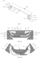
- FIG. 1 is a diagram of a structure of an electronic device according to an embodiment of this application.
- the electronic device may be a mobile phone, a personal digital assistant (personal digital assistant, PDA), a notebook computer, a tablet computer, or another device having a foldable function.
- the electronic device in the embodiment shown in FIG. 1 is described by using the mobile phone as an example.
- the electronic device may include a hinge mechanism, a flexible display, and two housings.
- the two housings may be respectively named a first housing 2 and a second housing 3.
- the first housing 2 and the second housing 3 are located on two sides of the hinge mechanism 1, and may rotate around the hinge mechanism 1.
- the electronic device may be folded and unfolded in different use scenarios.
- the electronic device provided in embodiments of this application may be an inwardly folded electronic device.
- the electronic device is in a folded state
- FIG. 1 shows a relative position relationship between the hinge mechanism 1 and the two housings when the electronic device is in the folded state.
- an appearance surface 1a of the hinge mechanism 1, a first appearance surface 2a of the first housing 2, and a second appearance surface 3a of the second housing 3 may be jointly used as an appearance surface of the electronic device.
- the appearance surface 1a of the hinge mechanism 1 is a surface that is of the hinge mechanism 1 and that is away from the flexible display
- the first appearance surface 2a of the first housing 2 is a surface that is of the first housing 2 and that is away from the flexible display
- the second appearance surface 3a of the second housing 3 is a surface that is of the second housing 3 and that is away from the flexible display.
- FIG. 2 is a diagram of a structure of the electronic device shown in FIG. 1 in an unfolded state. It should be noted that FIG. 2 shows structures of a support surface 1b of the hinge mechanism 1, a support surface 2b of the first housing 2, and a support surface 3b of the second housing 3.
- the support surface 1b of the hinge mechanism 1 is a surface that is of the hinge mechanism 1 and that is used to support the flexible display 4
- the support surface 2b of the first housing 2 is a surface that is of the first housing 2 and that is used to support the flexible display 4
- the support surface 3b of the second housing 3 is a surface that is of the second housing 3 and that is used to support the flexible display 4.
- the flexible display 4 may continuously cover the support surface 2b of the first housing 2, the support surface 1b of the hinge mechanism 1, and the support surface 3b of the second housing 3.
- the flexible display 4 may be fastened to the support surface 2b of the first housing 2 and the support surface 3b of the second housing 3, and a connection manner thereof may be but is not limited to bonding. In this way, when the electronic device is in the unfolded state shown in FIG. 2 , the hinge mechanism 1, the first housing 2, and the second housing 3 can support the flexible display 4.
- the flexible display 4 may be folded or unfolded with the first housing 2 and the second housing 3.
- FIG. 3 is a diagram of a partially exploded structure of the electronic device shown in FIG. 2 .
- the first housing 2 and the second housing 3 may be located on two opposite sides of the hinge mechanism 1.
- a side that is of the first housing 2 and that is close to the hinge mechanism 1 has a first mounting groove 201
- a side that is of the second housing 3 and that is close to the hinge mechanism 1 has a second mounting groove 301
- one side of the hinge mechanism 1 may be partially accommodated in the first mounting groove 201
- the other side of the hinge mechanism 1 may be partially accommodated in the second mounting groove 301.
- the hinge mechanism 1 may include one main shaft module 11, or may include a plurality of main shaft modules 11.
- FIG. 1 is a diagram of a partially exploded structure of the electronic device shown in FIG. 2 .
- the first housing 2 and the second housing 3 may be located on two opposite sides of the hinge mechanism 1.
- a side that is of the first housing 2 and that is close to the hinge mechanism 1 has a first mounting groove 201
- the hinge mechanism 1 includes two main shaft modules 11, and the two main shaft modules 11 may be spaced in a length direction of the hinge mechanism 1.
- the length direction of the hinge mechanism 1 may be understood as an extension direction of an axis around which the first housing 2 and the second housing 3 rotate around the hinge mechanism 1.
- the first housing 2 and the second housing 3 may be rotatably connected via the plurality of main shaft modules 11. This can effectively improve stability of rotation of the first housing 2 and the second housing 3 of the electronic device relative to the hinge mechanism 1.
- the main shaft module 11 may include two rotation components, and the two rotation components are a first rotation component 11a and a second rotation component 11b respectively.
- the hinge mechanism 1 may further include a base 12.
- the base 12 may be used as a bearing component of the first rotation component 11a and the second rotation component 11b, and the first rotation component 11a and the second rotation component 11b are disposed on two sides of the base 12 respectively.
- a surface of a side of the base 12 may be used as the support surface 1b of the hinge mechanism 1, to support the flexible display.
- the hinge mechanism 1 may further include an end cover 13, and the end cover 13 may cover a side that is of the base 12 and that is away from the support surface, to form accommodating space between the end cover 13 and the base 12. It is easy to understand that a surface of a side that is of the end cover 13 and that is away from the base 12 is an outer surface of the hinge mechanism 1, that is, a surface that is of the hinge mechanism 1 and that forms the appearance surface of the electronic device.
- the main shaft module 11 is described mainly by using a specific manner of disposing the first rotation component 11a and a connection relationship between the first rotation component 11a and the base 12 as an example, and the second rotation component 11b side may be disposed with reference to the first rotation component 11a side.
- a design of the second rotation component 11b may be completely the same as that of the first rotation component 11a; or reference may be made to only components and connection relationships included in the first rotation component 11a, and other parameters may be adaptively adjusted, and are not required to be completely the same.
- the first rotation component 11a and the second rotation component 11b of the plurality of main shaft modules 11 may all use a same base 12 as the bearing component, to improve an integration degree of the hinge mechanism 1.
- one base 12 corresponding to each main shaft module 11 may be disposed in the hinge mechanism 1, so that the first rotation component 11a and the second rotation component 11b of each main shaft module 11 use the corresponding base 12 as the bearing component.
- FIG. 4 is a diagram of an exploded structure of the hinge mechanism 1 according to an embodiment of this application.
- the first rotation component 11a may include a first support arm 111, the first support arm 111 is rotatably connected to the base 12, and a rotation axis center of the first support arm 111 is disposed in the length direction of the hinge mechanism 1.
- the first support arm 111 may further be fastened to the first housing, so that when the first support arm 111 rotates relative to the base 12, the first housing can be driven to synchronously rotate, thereby implementing switching between the folded state and the unfolded state of the electronic device.
- FIG. 5 is a diagram of a sectional structure of the base 12 according to an embodiment of this application
- FIG. 6 is a diagram of a structure of the first support arm 111 according to an embodiment of this application.
- a first arc-shaped rotation block 1111 may be disposed at one end that is of the first support arm 111 and that is connected to the base 12.
- a first arc-shaped groove 121 may be disposed on the base 12.
- the first arc-shaped rotation block 1111 of the first support arm 111 may be accommodated in the first arc-shaped groove 121, and may rotate along an arc-shaped surface of the first arc-shaped groove 121, so that the first support arm 111 rotates around the base 12.
- Such a manner in which the arc-shaped groove fits the arc-shaped rotation block to implement rotation around an axis center determined by a virtual position may be referred to as a rotatable connection manner of a virtual shaft.
- the two rotation entities do not directly rotate relative to each other via a physical pin shaft, but implement the rotatable connection via the foregoing fit structure.
- This connection manner helps reduce space occupied by the first support arm 111 on the base 12, thereby helping reduce a volume of the main shaft module and facilitating a miniaturization design of the hinge mechanism 1.
- the first arc-shaped rotation block 1111 may be but is not limited to a circular-arc-shaped rotation block, and the first arc-shaped groove 121 may be but is not limited to a circular-arc-shaped groove.
- the first arc-shaped rotation block 1111 may include two rotation sub-blocks, which are respectively a first rotation sub-block 1111a and a second rotation sub-block 1111b.
- the first rotation sub-block 1111a and the second rotation sub-block 1111b may be spaced in the length direction of the hinge mechanism.
- the first arc-shaped groove 121 may also include a first arc-shaped sub-groove 121a and a second arc-shaped sub-groove 121b, and the first arc-shaped sub-groove 121a and the second arc-shaped sub-groove 121b may also be spaced in the length direction of the hinge mechanism.
- the first rotation sub-block 1111a may be accommodated in the first arc-shaped sub-groove 121a, and may rotate along an arc-shaped surface of the first arc-shaped sub-groove 121a.
- the second rotation sub-block 1111b may be accommodated in the second arc-shaped sub-groove 121b, and may rotate along an arc-shaped surface of the second arc-shaped sub-groove 121b. Stability of motion of the first support arm 111 relative to the base 12 can be effectively improved through rotatable fit between the two groups of rotation sub-blocks and arc-shaped sub-grooves.
- first support arm 111 and the base 12 may alternatively be rotatably connected via a physical shaft.
- a hinged hole may be separately disposed on the first support arm 111 and the base 12, and the physical shaft is rotatably disposed in the hinged holes of the first support arm 111 and the base 12.
- the first support arm 111 may further include a first fastening block 1112 and a first connection block 1113.
- the first fastening block 1112 is located at an end that is of the first support arm 111 and that is away from the base 12, and the first connection block 1113 is located between the first fastening block 1112 and the first arc-shaped rotation block 1111, to connect the first fastening block 1112 to the first arc-shaped rotation block 1111.
- the first fastening block 1112 is located in the first mounting groove 201 (refer to FIG. 3 ) of the first housing 2, and the first fastening block 1112 has a first end surface 1112a and a second end surface 1112b that are disposed away from each other.
- the first end surface 1112a of the first fastening block 1112 may be aligned with the support surface 1a of the base 12, to provide flat support for the flexible display.
- the second end surface 1112b of the first fastening block 1112 is fastened to the first housing 2.
- a threaded hole is disposed on the second end surface 1112b of the first fastening block 1112, and the first fastening block 1112 may be fastened to the first housing 2 via a fastener.
- the first rotation component 11a may further include a first rotation plate 112, and the first rotation plate 112 is rotatably connected to the first support arm 111.
- the first rotation plate 112 may be rotatably connected to the first support arm 111 via a first pin shaft 113.
- FIG. 7 is a diagram of a structure of the first rotation plate 112 according to an embodiment of this application.
- the first rotation plate 112 includes a first side 112a and a second side 112b that are disposed opposite to each other.
- a first convex lug 1121 may be disposed on the first side 112a of the first rotation plate 112.
- the first convex lug 1121 may be located on one side of the first fastening block 1112, and a first through hole 11211 is disposed on the first convex lug 1121.
- a first hinged hole 11121 is disposed on a side surface of the first fastening block 1112, and the first pin shaft 113 is separately rotatably disposed in the first through hole 11211 and the first hinged hole 11121, so that the first rotation plate 112 is rotatably connected to the first support arm 111.
- the first hinged hole 11121 may be a blind hole.
- one end of the first pin shaft 113 is located on a side that is of the first convex lug 1121 and that is away from the first fastening block 1112, and the other end is located in the first hinged hole 11121.
- the first hinged hole 11121 may be a through hole.
- one end of the first pin shaft 113 is located on a side that is of the first convex lug 1121 and that is away from the first fastening block 1112, and the other end extends from the other side of the first fastening block 1112.
- first convex lugs 1121 there may be two first convex lugs 1121, and the two first convex lugs 1121 may be spaced in the length direction of the hinge mechanism.
- the two first convex lugs 1121 may be located on the two sides of the first fastening block 1112 respectively, and are separately rotatably connected to the first fastening block 1112 via the first pin shaft 113, so that reliability of a connection between the first rotation plate 112 and the first support arm 111 can be improved, and stability of rotation of the first rotation plate 112 can be further improved.
- the first convex lugs 1121 on the two sides may be separately hinged to the first fastening block 1112 via one first pin shaft 113.
- the first convex lugs 1121 on the two sides may share one first pin shaft 113 to implement hinging to the first fastening block 1112.
- a first stopper 11212 may be disposed on a surface that is of the first convex lug 1121 and that is away from the first support arm 111.
- the first stopper 11212 has a first extension rib 112121.
- the first extension rib 112121 and the first convex lug 1121 are spaced, and may be approximately parallel to each other. Projection of the first extension rib 112121 on a surface of the first convex lug 1121 may cover at least a part of the first through hole 11211.
- the first extension rib 112121 can stop and be disposed at an end part of the first pin shaft 113, so that a risk that the first pin shaft 113 falls off the first rotation plate 112 and the first support arm 111 can be reduced, and the reliability of the connection between the first rotation plate 112 and the first support arm 111 is improved.
- the first rotation component 11a may further include a first torsion spring 114, and the first torsion spring 114 may be sleeved on the first pin shaft 113.
- a position of disposing the first torsion spring 114 on the first pin shaft 113 is not limited.
- the first torsion spring 114 may be sleeved on a part that is of the first pin shaft 113 and that is located between the first convex lug 1121 of the first rotation plate 112 and the first fastening block 1112, so that the first convex lug 1121 and the first fastening block 1112 are used to limit axial (namely, the length direction of the hinge mechanism) movement of the first torsion spring 114.
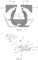
- FIG. 8a, FIG. 8b , and FIG. 8c are diagrams of sectional structures of the hinge mechanism in different states.
- Two ends of the first torsion spring 114 have a first torsion arm 1141 and a second torsion arm 1142 respectively.
- the first torsion arm 1141 of the first torsion spring 114 may be fastened to the first support arm 111, and the second torsion arm 1142 of the first torsion spring 114 may abut against the first side 112a of the first rotation plate 112. Refer to FIG. 6 and FIG. 7 together.
- a first extension block 11122 disposed beyond the first arc-shaped rotation block 1111 is disposed on a side of the first fastening block 1112, the first extension block 11122 may be disposed close to the second end surface 1112b of the first fastening block 1112, a first clamping groove 111221 is disposed on a side that is of the first extension block 11122 and that faces the first end surface 1112a of the first fastening block 1112, and the first torsion arm 1141 of the first torsion spring 114 may be disposed in the first clamping groove 111221.
- a first limiting groove 11213 is disposed on the first convex lug 1121, an opening of the first limiting groove 11213 is disposed away from the second side 112b of the first rotation plate 112, the second torsion arm 1142 of the first torsion spring 114 may be located in the first limiting groove 11213, and the second torsion arm 1142 of the first torsion spring 114 abuts against a groove bottom of the first limiting groove 11213.
- a first sink step 122 may be disposed on a side that is of the support surface 1b of the base 12 and that is close to the first rotation component 11a (refer to the base 12 shown in FIG. 5 together), and the sink step may be understood as a step whose step surface is lower than the support surface 1b of the base 12.
- the second side 112b of the first rotation plate 112 may be in lap joint with the first sink step 122, and in a specific design, a thickness of the first rotation plate 112 may be approximately the same as a height of the first sink step 122. In this way, in the unfolded state, a surface of a side that is of the first rotation plate 112 and that is away from the first sink step 122 can be aligned with the support surface 1b of the base 12, to provide the flat support for the flexible display.
- the first torsion spring 114 may be designed to be in a retracted state when the hinge mechanism 1 is in the unfolded state.
- the first rotation plate 112 has a trend of rotating clockwise and attaching to the first support arm 111 under an abutting action of the second torsion arm 1142 of the first torsion spring 114.
- the first sink step 122 limits the first rotation plate 112
- the rotation trend of the first rotation plate 112 is slowed down.
- the first rotation plate 112 is gradually free from limiting effect of the first sink step 122.
- the first rotation plate 112 When the first rotation plate 112 is completely free from limiting of the first sink step 122, the first rotation plate 112 may quickly rotate toward a direction of the first support arm 111 under the abutting action of the second torsion arm 1142 of the first torsion spring 114 until the first rotation plate 112 is attached to the first support arm 111. In this case, the hinge mechanism 1 is also switched to the folded state with rotation of the first support arm 111, and water-drop-like screen-accommodating space is formed.
- the first rotation plate 112 when the hinge mechanism 1 is in the folded state, the first rotation plate 112 does not occupy the screen-accommodating space, thereby helping increase an available volume of the screen-accommodating space and meeting a bending requirement of the flexible display.
- the first torsion spring 114 may still be in a partially retracted state, that is, in this case, the first torsion spring 114 may still apply specific abutting force to the first rotation plate 112, so that the first rotation plate 112 can be firmly attached to the first support arm 111, and the screen-accommodating space of the hinge mechanism 1 in the folded state is always in a consistent form, thereby avoiding squeezing the flexible display in a falling process of the entire electronic device, and improving reliability of the flexible display.
- a first groove 1114 may be disposed on a side that is of the first support arm 111 and that faces the first rotation plate 112 (refer to the first support arm shown in FIG. 6 together).
- the first rotation plate 112 When the hinge mechanism is in the folded state, the first rotation plate 112 may be located in the first groove 1114, and the first rotation plate 112 is attached to a bottom wall of the first groove 1114. This helps further increase the available volume of the screen-accommodating space.
- the first groove 1114 may be specifically disposed on the first connection block 1113.
- one end of the first connection block 1113 may be connected to an end that is of the first fastening block 1112 and that is close to the first end surface 1112a, and the first end surface 1112a of the first fastening block 1112 and a corresponding side surface of the first connection block 1113 form smooth transition at a joint.
- the other end of the first connection block 1113 is connected to an outer arc wall of the first arc-shaped rotation block 1111.
- a mismatch gap can be formed between an inner arc wall of the first connection block 1113 and the first arc-shaped rotation block 1111, and the first connection block 1113 and the first arc-shaped rotation block 1111 may form the first groove 1114 by using the mismatch gap.
- the second rotation component 11b and the first rotation component 11a may be disposed on the two sides of the base 12 respectively.
- the second rotation component 11b may also include a second support arm 115, a second rotation plate 116, a second pin shaft 117, and a second torsion spring 118.
- a second arc-shaped rotation block 1151 may be disposed at an end that is of the second support arm 115 and that is configured to connect to the base 12, a second arc-shaped groove 123 may be disposed on the base 12, and the second arc-shaped rotation block 1151 is slidably disposed in the second arc-shaped groove 123.
- the second arc-shaped groove 123 and the first arc-shaped groove 121 may be staggered in the length direction of the hinge mechanism 1. In this way, sufficient rotation space can be provided for the first arc-shaped rotation block 1111 and the second arc-shaped rotation block 1151 by increasing depths of the first arc-shaped groove 121 and the second arc-shaped groove 123, a risk of interference between the first arc-shaped groove 121 and the second arc-shaped groove 123 in the base 12 can be reduced, and groove opening positions in the base 12 can be dispersed, thereby avoiding excessively concentrated structural weak points on the base 12.
- the second arc-shaped rotation block 1151 may include a third rotation sub-block 1151a and a fourth rotation sub-block 1151b that are disposed in the length direction of the hinge mechanism 1.
- the second arc-shaped groove 123 may also include a third arc-shaped sub-groove 123a and a fourth arc-shaped sub-groove 123b.
- the third rotation sub-block 1151a is rotatably disposed in the third arc-shaped sub-groove 123a
- the fourth rotation sub-block 1151b is rotatably disposed in the fourth arc-shaped sub-groove 123b.
- the second support arm 115 may further include a second fastening block 1152 and a second connection block 1153.
- the second fastening block 1152 is located at an end that is of the second support arm 115 and that is away from the base 12, and the second connection block 1153 is connected between the second fastening block 1152 and the second arc-shaped rotation block 1151.
- the second fastening block 1152 is located in the second mounting groove 301 (refer to FIG. 3 ) of the second housing 3, and the second fastening block 1152 may have a first end surface and a second end surface that are disposed away from each other.
- the first end surface of the second fastening block 1152 may be aligned with the support surface of the base 12, to provide the flat support for the flexible display.
- the second end surface of the second fastening block 1152 is fastened to the second housing 3.
- a first side of the second rotation plate 116 may be rotatably connected to the second support arm 115 via the second pin shaft.
- a second convex lug 1161 may be disposed on the first side of the second rotation plate 116, and a second through hole is disposed on the second convex lug 1161.
- a hinged hole is disposed on a side surface of the second fastening block 1152, and the second pin shaft 117 is separately rotatably disposed in the second through hole and the hinged hole.
- the two second convex lugs 1161 may be located on two sides of the second fastening block 1152 respectively, and are separately rotatably connected to the second fastening block 1152 via the second pin shaft 117.
- a second stopper may be disposed on a surface that is of the second convex lug 1161 and that is away from the second support arm 115, the second stopper has a second extension rib, the second extension rib and the second convex lug 1161 are spaced, and projection of the second extension rib on a surface of the second convex lug 1161 may cover at least a part of the second through hole.
- the second torsion spring 118 may be sleeved on the second pin shaft 117. Two ends of the second torsion spring 118 have a first torsion arm 1181 and a second torsion arm 1182 respectively. The first torsion arm 1181 of the second torsion spring 118 may be fastened to the second support arm 115, and the second torsion arm 1182 of the second torsion spring 118 may abut against the first side of the second rotation plate 116.
- a second limiting groove may be disposed on the second convex lug, an opening of the second limiting groove is disposed away from a second side of the second rotation plate 116, and the second torsion arm 1182 of the second torsion spring 118 may be located in the second limiting groove.
- a second sink step 124 may be disposed on a side that is of the support surface 1b of the base 12 and that is close to the second rotation component 11b.
- the second side of the second rotation plate 116 may be in lap joint with the second sink step 124, and a surface of a side that is of the second rotation plate 116 and that is away from the second sink step 124 may be aligned with the support surface 1b of the base 12, to provide the flat support for the flexible display.
- the second torsion spring 118 may also be designed to be in the retracted state when the hinge mechanism 1 is in the unfolded state.
- the second rotation plate 116 is gradually free from limiting effect of the second sink step 124.
- the second rotation plate 116 may quickly rotate toward a direction of the second support arm 115 under the abutting action of the second torsion arm 1182 of the second torsion spring 118 until the second rotation plate 116 is attached to the second support arm 115.
- the hinge mechanism 1 is also switched to the folded state with rotation of the second support arm 115, and the water-drop-like screen-accommodating space is formed.
- the second torsion spring 118 may still be in a partially retracted state, so that the second rotation plate 116 can be firmly attached to the second support arm 115 under the action of the second torsion arm 1182 of the second torsion spring 118.
- a second groove 1154 may be disposed on a side that is of the second support arm 115 and that faces the second rotation plate 116.
- the second rotation plate 116 may be located in the second groove 1154, to further increase the available volume of the screen-accommodating space.
- FIG. 9a is a diagram of a structure of the hinge mechanism 1 in the unfolded state according to an embodiment of this application
- FIG. 9b is a diagram of an assembly structure of the hinge mechanism 1 in the unfolded state and the flexible display 4 according to an embodiment of this application. It should be noted that the first rotation plate 112 and the second rotation plate 116 are omitted in FIG. 9a .
- the first torsion spring 114 and the second torsion spring 118 are both in the retracted state
- the first rotation plate 112 is in lap joint with the first sink step 122
- the second rotation plate 116 is in lap joint with the second sink step 124
- the first end surface of the first fastening block 1112 and the surface of the side that is of the first rotation plate 112 and that is away from the first sink step 122 are separately aligned with the support surface 1b of the base 12
- the first end surface of the second fastening block 1152 and the surface of the side that is of the second rotation plate 116 and that is away from the second sink step 124 are also separately aligned with the support surface 1b of the base 12.
- a highest end surface of the first rotation component 11a and a highest end surface of the second rotation component 11b are both aligned with the support surface 1b of the base 12, and there is almost no mismatch gap on the surface of the support surface side of the hinge mechanism 1, thereby greatly improving flatness of an area of the hinge mechanism 1 of the entire electronic device and providing the flat support for the flexible display 4.
- FIG. 10 is a diagram of a structure of the hinge mechanism 1 in an intermediate state according to an embodiment of this application.
- the first torsion spring 114 releases accumulated elastic potential energy slowly
- the first rotation plate 112 may rotate slightly relative to the first support arm 111 under the action of the first torsion spring 114, and the second side of the first rotation plate 112 gradually moves toward an edge of the first sink step 122 until the first support arm 111 rotates to a specific angle.
- the first rotation plate 112 may be free from the limiting of the first sink step 122.
- the second rotation plate 116 also rotates slightly relative to the second support arm 115 under the action of the second torsion spring 118, and the second side of the second rotation plate 116 gradually moves toward an edge of the second sink step 124 until the second support arm 115 rotates to a specific angle.
- the second rotation plate 116 may be free from the limiting of the second sink step 124.
- FIG. 11a is a diagram of a structure of the hinge mechanism 1 in the folded state according to an embodiment of this application
- FIG. 11b is a diagram of an assembly structure of the hinge mechanism 1 in the folded state and the flexible display 4 according to an embodiment of this application.
- the second torsion spring 118 may push the second rotation plate 116 to quickly rotate in the direction of the second support arm 115 until the second rotation plate 116 is attached to the second support arm 115.
- the water-drop-like screen-accommodating space may be formed between the first rotation component 11a, the second rotation component 11b, and the base 12, thereby meeting the bending requirement of the flexible display 4 of the electronic device, reducing a risk of squeezing or stretching the flexible display 4, and prolonging a service life of the flexible display 4.
- a damping component that can provide damping force for the first rotation component 11a and the second rotation component 11b may be further disposed on the hinge mechanism 1, so that the first rotation component 11a and the second rotation component 11b can rotate stably under the action of the damping force, thereby avoiding false unfolding and folding of the electronic device and implementing suspension of the two housings in specified positions.
- the hinge mechanism 1 may include one damping component.
- the damping component may be disposed corresponding to the first rotation component 11a or the second rotation component 11b of one main shaft module.
- the hinge mechanism 1 may include a plurality of damping components.
- the plurality of damping components may be disposed corresponding to the first rotation component 11a and the second rotation component 11b in at least one main shaft module.
- FIG. 4 shows a case in which the hinge mechanism 1 includes four damping components.
- the four damping components may be disposed corresponding to the first rotation components 11a and the second rotation components 11b in the two main shaft modules respectively.
- the damping component disposed corresponding to the first rotation component 11a is referred to as a first damping component 14a
- the damping component disposed corresponding to the second rotation component 11b is referred to as a second damping component 14b.
- the following mainly uses a manner of disposing the first damping component 14a and a connection relationship between the first damping component 14a and the first rotation component 11a as an example for description.
- the second damping component 14b may be disposed with reference to the first damping component 14a.
- a first mounting hole 125 extending in the length direction of the hinge mechanism 1 may be disposed on the base 12.
- the first mounting hole 125 may be in communication with the first arc-shaped groove 121 configured to accommodate the first arc-shaped rotation block 1111.
- the first damping component 14a may be mounted in the first mounting hole 125.
- An end that is of the first arc-shaped rotation block 1111 and that faces the first mounting hole 125 may have a first cam surface 11111 (refer to the first support arm 111 shown in FIG. 6 ).
- the cam surface may be understood as a surface formed by a curved contour on the first arc-shaped rotation block 1111.
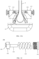
- FIG. 12 is a diagram of an exploded structure of the first damping component 14a according to an embodiment of this application.
- the first damping component 14a may include a first stop block 141, a first cam 142, and a first elastic member 143.
- the first stop block 141 may be fastened to the first mounting hole 125.
- the first cam 142 is located on a side that is of the first stop block 141 and that faces the first arc-shaped groove 121, the first cam 142 may slide in the first mounting hole 125, and a side that is of the first cam 142 and that is away from the first stop block 141 has a second cam surface 1421.
- the first elastic member 143 may be limited between the first stop block 141 and the first cam 142.
- the first stop block 141 may be a screw nut shown in FIG. 12 , at least a part of an inner wall that is of the first mounting hole 125 and that is close to an opening of the hole has an internal screw thread, and the first stop block 141 may be fastened to the first mounting hole 125 in a threaded connection manner. In some other implementations, the first stop block 141 may alternatively be fastened to the first mounting hole 125 in an interference fit manner.
- the first elastic member 143 may be a spring shown in FIG. 12 .
- the first damping component 14a may further include a first guiding pillar 144 located between the first stop block 141 and the first cam 142, and the first elastic member 143 may be sleeved over the first guiding pillar 144, to avoid displacement of the first elastic member 143 when elastic deformation occurs.
- the first guiding pillar 144 and the first cam 142 may be of an integrated structure, to simplify an assembly process of the first damping component 14a on the hinge mechanism 1.
- the first elastic member 143 may alternatively be a spring plate, there may be a plurality of spring plates, and the plurality of spring plates are stacked between the first stop block 141 and the first cam 142.
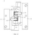
- FIG. 13 is a diagram of a partial structure of the hinge mechanism 1 according to an embodiment of this application. Refer to FIG. 12 and FIG. 13 together.
- the first damping component 14a When the first damping component 14a is mounted in the first mounting hole 125, the first elastic member 143 is gradually compressed as the first stop block 141 is screwed into the first mounting hole 125.
- the second cam surface 1421 of the first cam 142 Under an action of the first elastic member 143, the second cam surface 1421 of the first cam 142 may abut against the first cam surface 11111 of the first arc-shaped rotation block 1111.
- the first cam 142 and the first arc-shaped rotation block 1111 may form a cam pair.
- curved surface contours of the first cam surface 11111 and the second cam surface 1421 are properly designed, so that in the process in which the hinge mechanism 1 is folded, the first arc-shaped rotation block 1111 can push the first cam 142 toward a direction close to the first stop block 141, thereby compressing the first elastic member 143.
- the first elastic member 143 gradually rebounds from a compressed state, and releases accumulated elastic potential energy, to push the first cam 142 to slide in a direction away from the first stop block 141.
- the first cam 142 can apply torque force to the first arc-shaped rotation block 1111 to facilitate rotation of the first arc-shaped rotation block 1111, thereby providing specific unfolding assistance for the hinge mechanism 1 and further reducing unfolding operation difficulty of the hinge mechanism 1.
- the first cam surface 11111 and the second cam surface 1421 are properly designed, so that the first arc-shaped rotation block 1111 can be suspended at a specified angle, that is, the first support arm 111 is suspended.
- the electronic device may be positioned in some intermediate states by using a suspendable design of the first support arm 111, thereby further improving user experience.
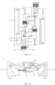
- FIG. 14 is a diagram of a partially sectional structure of the hinge mechanism 1 according to an embodiment of this application.
- the hinge mechanism 1 may further include a synchronization component 15.
- the synchronization component 15 may include a first gear tooth 151 disposed on the outer arc wall of the first arc-shaped rotation block 1111, and a second gear tooth (not shown in the figure) disposed on an outer arc wall of the second arc-shaped rotation block 1151.
- the first gear tooth 151 is in transmission connection to the second gear tooth.
- the other support arm in a process in which one support arm rotates around the base, the other support arm can be driven to synchronously rotate in a direction toward or away from to the one support arm, and rotation angles of the two support arms are consistent.
- the first housing and the second housing of the electronic device in a process in which the two support arms synchronously rotate, can be driven to synchronously rotate, so that instantaneous force can be avoided from being applied to the flexible display fastened to the two housings, thereby improving the reliability of the flexible display.
- FIG. 15 is a diagram of a partial structure of a side that is of the hinge mechanism 1 and that is away from the support surface of the hinge mechanism 1 according to an embodiment of this application.
- the synchronization component 15 may further include a first rack 153, a second rack 154, and a synchronization gear 155.
- the first rack 153 and the second rack 154 may be spaced in the length direction of the hinge mechanism 1, and the first rack 153 and the second rack 154 may be slidably disposed on the base in a width direction of the base.
- the first rack 153 is meshed with the first gear tooth 151 on the first arc-shaped rotation block 1111
- the second rack 154 is meshed with the second gear tooth 152 on the second arc-shaped rotation block 1151
- the synchronization gear 155 is located between the first rack 153 and the second rack 154
- the synchronization gear 155 is separately meshed with the first rack 153 and the second rack 154.
- the first rack 153 and the second rack 154 can synchronously slide toward or away from each other via the synchronization gear 155, so that the first arc-shaped rotation block 1111 meshed with the first rack 153 and the second arc-shaped rotation block 1151 meshed with the second rack 154 can synchronously rotate toward or away from each other.
- a first opening groove 126 and a second opening groove 127 may be disposed on a side that is of the base 12 and that is away from the support surface 1b (refer to the base shown in FIG. 5 ), and the first opening groove 126 may be in communication with the first arc-shaped groove 121, and the second opening groove 127 may be in communication with the second arc-shaped groove 123.
- the first gear tooth 151 may be disposed in an area in which the first arc-shaped rotation block 1111 is exposed to the first opening groove 126, and the first rack 153 is slidably disposed in the first opening groove 126, so that the first gear tooth 151 is meshed with the first rack 153.
- the second gear tooth 152 may be disposed in an area in which the second arc-shaped rotation block 1151 is exposed to the second opening groove 127, and the second rack 154 is slidably disposed in the second opening groove 127, so that the second gear tooth 152 is meshed with the second rack 154.
Landscapes
- Engineering & Computer Science (AREA)
- General Engineering & Computer Science (AREA)
- Theoretical Computer Science (AREA)
- Physics & Mathematics (AREA)
- Computer Hardware Design (AREA)
- General Physics & Mathematics (AREA)
- Mechanical Engineering (AREA)
- Human Computer Interaction (AREA)
- Microelectronics & Electronic Packaging (AREA)
- Signal Processing (AREA)
- Mathematical Physics (AREA)
- Pivots And Pivotal Connections (AREA)
- Telephone Set Structure (AREA)
- Casings For Electric Apparatus (AREA)
Applications Claiming Priority (2)
| Application Number | Priority Date | Filing Date | Title |
|---|---|---|---|
| CN202211707094.7A CN118274012B (zh) | 2022-12-29 | 2022-12-29 | 一种转轴机构及电子设备 |
| PCT/CN2023/119926 WO2024139437A1 (fr) | 2022-12-29 | 2023-09-20 | Mécanisme d'arbre rotatif et dispositif électronique |
Publications (2)
| Publication Number | Publication Date |
|---|---|
| EP4545814A1 true EP4545814A1 (fr) | 2025-04-30 |
| EP4545814A4 EP4545814A4 (fr) | 2025-11-19 |
Family
ID=91638714
Family Applications (1)
| Application Number | Title | Priority Date | Filing Date |
|---|---|---|---|
| EP23909372.7A Pending EP4545814A4 (fr) | 2022-12-29 | 2023-09-20 | Mécanisme d'arbre rotatif et dispositif électronique |
Country Status (4)
| Country | Link |
|---|---|
| US (1) | US20250169002A1 (fr) |
| EP (1) | EP4545814A4 (fr) |
| CN (1) | CN118274012B (fr) |
| WO (1) | WO2024139437A1 (fr) |
Families Citing this family (1)
| Publication number | Priority date | Publication date | Assignee | Title |
|---|---|---|---|---|
| US12484170B2 (en) * | 2024-03-13 | 2025-11-25 | Robe Lighting S.R.O. | Console display hinge system |
Family Cites Families (7)
| Publication number | Priority date | Publication date | Assignee | Title |
|---|---|---|---|---|
| TWI366431B (en) * | 2008-05-05 | 2012-06-11 | Asustek Comp Inc | Torsion spring assembly and portable electronic device with torsion spring assembly |
| CN210377243U (zh) * | 2019-10-30 | 2020-04-21 | Oppo广东移动通信有限公司 | 电子设备 |
| KR102798666B1 (ko) * | 2019-12-13 | 2025-04-18 | 후아웨이 테크놀러지 컴퍼니 리미티드 | 회전축 구조체 및 전자 장치 |
| CN114338864A (zh) * | 2020-09-30 | 2022-04-12 | 华为技术有限公司 | 折叠装置及电子设备 |
| CN113833741B (zh) * | 2020-06-24 | 2023-04-07 | 华为技术有限公司 | 一种折叠装置及电子设备 |
| CN113719525B (zh) * | 2021-07-16 | 2025-01-28 | 昆山玮硕恒基智能科技股份有限公司 | 一种旋转铰链、折叠机壳和电子设备 |
| CN114623148B (zh) * | 2022-02-21 | 2025-08-19 | 苏州领页智能科技有限公司 | 一种内折柔性屏移动终端的铰链 |
-
2022
- 2022-12-29 CN CN202211707094.7A patent/CN118274012B/zh active Active
-
2023
- 2023-09-20 EP EP23909372.7A patent/EP4545814A4/fr active Pending
- 2023-09-20 WO PCT/CN2023/119926 patent/WO2024139437A1/fr not_active Ceased
-
2025
- 2025-01-17 US US19/028,526 patent/US20250169002A1/en active Pending
Also Published As
| Publication number | Publication date |
|---|---|
| WO2024139437A1 (fr) | 2024-07-04 |
| US20250169002A1 (en) | 2025-05-22 |
| CN118274012A (zh) | 2024-07-02 |
| EP4545814A4 (fr) | 2025-11-19 |
| CN118274012B (zh) | 2025-10-31 |
Similar Documents
| Publication | Publication Date | Title |
|---|---|---|
| US11914433B2 (en) | Hinge and mobile terminal | |
| US11846997B2 (en) | Rotating shaft mechanism and mobile terminal | |
| US12314091B2 (en) | Folding mechanism and electronic device | |
| US20240384751A1 (en) | Hinge mechanism and electronic device | |
| EP3955555A1 (fr) | Mécanisme d'arbre rotatif et terminal mobile pliable | |
| US20210381289A1 (en) | Complex moving/rotating pivot shaft device | |
| EP4354835A1 (fr) | Mécanisme de pliage et dispositif électronique | |
| US20250048572A1 (en) | Hinge mechanism and electronic device | |
| EP4485908A1 (fr) | Mécanisme d'arbre rotatif et dispositif pliable | |
| US12572183B2 (en) | Rotating shaft mechanism and electronic device | |
| EP4474662A1 (fr) | Mécanisme de charnière et dispositif électronique | |
| WO2022228158A1 (fr) | Mécanisme de pliage et dispositif électronique | |
| US20250169002A1 (en) | Hinge Mechanism and Electronic Device | |
| CN116069130A (zh) | 张紧结构、转轴机构及电子设备 | |
| WO2023071978A1 (fr) | Mécanisme d'arbre rotatif et dispositif électronique | |
| EP4545813A1 (fr) | Dispositif électronique pliable et mécanisme d'arbre rotatif associé | |
| EP4560159A1 (fr) | Mécanisme d'arbre rotatif et dispositif électronique | |
| CN116708613B (zh) | 可折叠机构和可折叠终端 | |
| CN116085384B (zh) | 同步转动装置、转轴机构及折叠式电子设备 | |
| WO2024131443A1 (fr) | Dispositif électronique pliable et charnière | |
| CN115623711B (zh) | 转轴组件及折叠屏终端 | |
| EP4509733A1 (fr) | Charnière et dispositif pliable | |
| CN121025041B (zh) | 转轴机构及终端设备 | |
| CN119957602B (zh) | 转轴机构、可折叠壳体及可折叠电子设备 | |
| US20250031330A1 (en) | Hinge Mechanism and Electronic Device |
Legal Events
| Date | Code | Title | Description |
|---|---|---|---|
| STAA | Information on the status of an ep patent application or granted ep patent |
Free format text: STATUS: THE INTERNATIONAL PUBLICATION HAS BEEN MADE |
|
| PUAI | Public reference made under article 153(3) epc to a published international application that has entered the european phase |
Free format text: ORIGINAL CODE: 0009012 |
|
| STAA | Information on the status of an ep patent application or granted ep patent |
Free format text: STATUS: REQUEST FOR EXAMINATION WAS MADE |
|
| 17P | Request for examination filed |
Effective date: 20250123 |
|
| AK | Designated contracting states |
Kind code of ref document: A1 Designated state(s): AL AT BE BG CH CY CZ DE DK EE ES FI FR GB GR HR HU IE IS IT LI LT LU LV MC ME MK MT NL NO PL PT RO RS SE SI SK SM TR |
|
| A4 | Supplementary search report drawn up and despatched |
Effective date: 20251020 |
|
| RIC1 | Information provided on ipc code assigned before grant |
Ipc: F16C 11/04 20060101AFI20251014BHEP Ipc: H04M 1/02 20060101ALI20251014BHEP |
|
| GRAP | Despatch of communication of intention to grant a patent |
Free format text: ORIGINAL CODE: EPIDOSNIGR1 |
|
| STAA | Information on the status of an ep patent application or granted ep patent |
Free format text: STATUS: GRANT OF PATENT IS INTENDED |
|
| DAV | Request for validation of the european patent (deleted) | ||
| DAX | Request for extension of the european patent (deleted) | ||
| INTG | Intention to grant announced |
Effective date: 20260203 |