EP4545836A1 - Rohrverbindungssystem - Google Patents
Rohrverbindungssystem Download PDFInfo
- Publication number
- EP4545836A1 EP4545836A1 EP24207692.5A EP24207692A EP4545836A1 EP 4545836 A1 EP4545836 A1 EP 4545836A1 EP 24207692 A EP24207692 A EP 24207692A EP 4545836 A1 EP4545836 A1 EP 4545836A1
- Authority
- EP
- European Patent Office
- Prior art keywords
- pipe
- connection block
- tubular terminal
- connecting system
- hole
- Prior art date
- Legal status (The legal status is an assumption and is not a legal conclusion. Google has not performed a legal analysis and makes no representation as to the accuracy of the status listed.)
- Granted
Links
Images
Classifications
-
- F—MECHANICAL ENGINEERING; LIGHTING; HEATING; WEAPONS; BLASTING
- F16—ENGINEERING ELEMENTS AND UNITS; GENERAL MEASURES FOR PRODUCING AND MAINTAINING EFFECTIVE FUNCTIONING OF MACHINES OR INSTALLATIONS; THERMAL INSULATION IN GENERAL
- F16L—PIPES; JOINTS OR FITTINGS FOR PIPES; SUPPORTS FOR PIPES, CABLES OR PROTECTIVE TUBING; MEANS FOR THERMAL INSULATION IN GENERAL
- F16L39/00—Joints or fittings for double-walled or multi-channel pipes or pipe assemblies
-
- F—MECHANICAL ENGINEERING; LIGHTING; HEATING; WEAPONS; BLASTING
- F28—HEAT EXCHANGE IN GENERAL
- F28F—DETAILS OF HEAT-EXCHANGE AND HEAT-TRANSFER APPARATUS, OF GENERAL APPLICATION
- F28F9/00—Casings; Header boxes; Auxiliary supports for elements; Auxiliary members within casings
- F28F9/02—Header boxes; End plates
- F28F9/0246—Arrangements for connecting header boxes with flow lines
- F28F9/0251—Massive connectors, e.g. blocks; Plate-like connectors
- F28F9/0253—Massive connectors, e.g. blocks; Plate-like connectors with multiple channels, e.g. with combined inflow and outflow channels
-
- F—MECHANICAL ENGINEERING; LIGHTING; HEATING; WEAPONS; BLASTING
- F16—ENGINEERING ELEMENTS AND UNITS; GENERAL MEASURES FOR PRODUCING AND MAINTAINING EFFECTIVE FUNCTIONING OF MACHINES OR INSTALLATIONS; THERMAL INSULATION IN GENERAL
- F16L—PIPES; JOINTS OR FITTINGS FOR PIPES; SUPPORTS FOR PIPES, CABLES OR PROTECTIVE TUBING; MEANS FOR THERMAL INSULATION IN GENERAL
- F16L41/00—Branching pipes; Joining pipes to walls
- F16L41/08—Joining pipes to walls or pipes, the joined pipe axis being perpendicular to the plane of a wall or to the axis of another pipe
- F16L41/086—Joining pipes to walls or pipes, the joined pipe axis being perpendicular to the plane of a wall or to the axis of another pipe fixed with screws
-
- F—MECHANICAL ENGINEERING; LIGHTING; HEATING; WEAPONS; BLASTING
- F16—ENGINEERING ELEMENTS AND UNITS; GENERAL MEASURES FOR PRODUCING AND MAINTAINING EFFECTIVE FUNCTIONING OF MACHINES OR INSTALLATIONS; THERMAL INSULATION IN GENERAL
- F16L—PIPES; JOINTS OR FITTINGS FOR PIPES; SUPPORTS FOR PIPES, CABLES OR PROTECTIVE TUBING; MEANS FOR THERMAL INSULATION IN GENERAL
- F16L41/00—Branching pipes; Joining pipes to walls
- F16L41/08—Joining pipes to walls or pipes, the joined pipe axis being perpendicular to the plane of a wall or to the axis of another pipe
- F16L41/14—Joining pipes to walls or pipes, the joined pipe axis being perpendicular to the plane of a wall or to the axis of another pipe by screwing an intermediate part against the inside or outside of the wall
Definitions
- the present invention relates to a pipe connecting system, particularly for the air conditioning systems in motor vehicles.
- the present invention relates to a pipe connecting system comprising:
- At the second side of the connection block at least one threaded insert may be inserted for securing, via a respective screw, the first tubular terminal and the second tubular terminal to the connection block.
- the first tubular terminal and the second tubular terminal are specifically inserted into respective enlarged internal diameter portions of the first pipe and the second pipe respectively.
- the first tubular terminal and the second tubular terminal can be provided with at least one support portion extending laterally and bearing a through-hole suitable for receiving a respective screw for coupling to said at least one threaded insert.
- the method according to the invention allows the direct connection of pipes, without requiring a third element to achieve fluidic continuity, and provides retention of the pipes that allows supporting and securing the first and second pipe (which, in this case, may be pipes on heat exchanger side) relative to the vehicle, as well as the connection to the first tubular terminal and the second tubular terminal (which, in this case, may be terminals on the vehicle system side).
- This is essentially achieved by a plastic connection block and a locking plate coupled to the connection block.
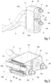
- FIGS 1-3 show a pipe connecting system, which may be provided for connecting a heat exchanger of an air conditioning unit, for example an evaporator (not shown), to a circuit installed in a motor vehicle (not shown) for the circulation of a refrigerant.
- the heat exchanger can be connected to a pair of pipes 2 and 3 of metal material (for example, one for the inlet to the heat exchanger and one for the outlet from the heat exchanger).
- connection block 10 a first tubular terminal and a second tubular terminal of metal material are also shown, respectively denoted by 4 and 5, which are also connected to the connection block 10 and belong to the refrigerant circuit to which the heat exchanger is connected.
- a first side 11 intended to receive the first pipe and the second pipe 2, 3, and a second side 12 opposite the first side 11 and intended to receive the first tubular terminal and the second tubular terminal 4, 5, can be identified.
- the first pipe and the second pipe 2, 3 each comprise a flaring end 2a, 3a.
- Each flaring end 2a, 3a comprises a flare 2a', 3a' and, at a distal position relative to the flare 2a', 3a', there is an enlarged diameter portion 2a", 3a".
- Each enlarged diameter portion 2a", 3a" has a larger diameter than the remaining part of the respective pipe and is connected to said remaining part by the respective flare 2a', 3a'.
- distal and proximal mean “farther” and "closer,” respectively to the item to which the first pipe and the second pipe are associated, which in the illustrated example consists of a heat exchanger.
- first pipe and the second pipe 2, 3 each comprise a flanged portion 2b, 3b extending radially outward and positioned near the respective flaring end 2a, 3a, proximally to it.
- the flared portion and the flanged portion are formed on the pipes using conventional pipe manufacturing techniques.
- the connection block 10 is a one-piece body made of plastic material, through which a first through-hole 13 and a second through-hole 14 are formed. These through-holes 13, 14 are configured to house the flaring ends 2a, 3a of the first and second pipes 2, 3, respectively. More precisely, when the first pipe and the second pipe 2, 3 are inserted into the connection block 10, the through-holes 13, 14 house not only the respective flaring ends 2a, 3a of the pipes 2, 3 but also a section of the pipe located between the flaring ends 2a, 3a and the respective flanged portions 2b, 3b. Additionally, the enlarged diameter portions 2a", 3a" of the pipes 2, 3 are in contact with the lateral surface of the respective through-holes 13, 14 of the connection block 10.
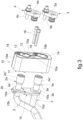
- the pipe connecting system further comprises a locking plate 15 of metal material, which includes an engagement portion 15a configured to engage simultaneously the flanged portions 2b, 3b of the first pipe and the second pipe 2, 3.
- the locking plate 15 has a pair of loops (only one of which is visible in the figures, denoted by 15b) with transverse dimensions slightly larger than the outer diameter of the first pipe 2 and the second pipe 3, but smaller than the outer diameter of the flanged portions 2b and 3b, respectively. This allows the locking plate 15 to be assembled to the pipes 2 and 3 and moved along the pipes until it engages with the flanged portions 2b and 3b.
- the engagement portion 15a provided by the locking plate 15 is formed by portions of the surface of the plate facing the connection block, which are arranged around the edges of the loops 15b, 15c.
- the locking plate 15 is secured to the connection block 10 by at least one screw 16 (in the example, two screws) to hold the first pipe and the second pipe 2, 3 between the connection block 10 and the locking plate 15.
- through-holes 10a are formed in the connection block 10 to allow the placement of screws 16, while threaded through-holes 15d are formed in the locking plate, into which the threads of screws 16 engage.
- the screws 16 act as tie rods, applying a clamping force acting on one end of the screws at the locking plate 15, and on the other end of the screws at the second side 12 of the connection block 10.
- the screws 16 thus enable the clamping of the locking plate 15 against the flanged portions 2b, 3b of the pipes 2, 3, thereby clamping those flanged portions against the connection block 10. It should be noted that no other screws are required for the integrity of the pipe connecting system besides those used to secure the locking plate 15 to the connection block 10.
- first tubular terminal 4 and the second tubular terminal 5 are inserted into the respective enlarged diameter portions 2a" and 3a" of the first pipe 2 and the second pipe 3, respectively.
- respective gaskets 17 are interposed between the radially outer surface of each of first tubular terminal and second tubular terminal 4, 5 and the radially inner surface of respective enlarged diameter portions 2a" and 3a".
- the first tubular terminal 4 and the second tubular terminal 5 are provided with at least one support portion 4a, 5a (in the example, one support portion each), extending laterally and having a through-hole suitable for receiving a respective screw 4b, 5b for the coupling to the connection block 10. More specifically, threaded inserts 18 are inserted at the second side 12 of the connection block 10 for securing the first tubular terminal 4 and the second tubular terminal 5 to the connection block 10 via screws 4b, 5b. These threaded inserts 18 may be inserted into the connection block 10 during the moulding process of the connection block 10 or may be implanted into the connection block 10 in a subsequent stage after its moulding.
- a first gasket 19a and a second gasket 19b are also arranged, respectively around the first through-hole 13 and the second through-hole 14. These gaskets are configured to be interposed between the second side 12 of the connection block 10 and the respective support portions 4a, 5a of the first tubular terminal 4 and the second tubular terminal 5.
- the gaskets 19a, 19b can be formed on the connection block 10 using a multi-material moulding technique.
Landscapes
- Engineering & Computer Science (AREA)
- General Engineering & Computer Science (AREA)
- Mechanical Engineering (AREA)
- Physics & Mathematics (AREA)
- Thermal Sciences (AREA)
- Quick-Acting Or Multi-Walled Pipe Joints (AREA)
Applications Claiming Priority (1)
| Application Number | Priority Date | Filing Date | Title |
|---|---|---|---|
| IT202300022440 | 2023-10-26 |
Publications (3)
| Publication Number | Publication Date |
|---|---|
| EP4545836A1 true EP4545836A1 (de) | 2025-04-30 |
| EP4545836B1 EP4545836B1 (de) | 2025-12-03 |
| EP4545836C0 EP4545836C0 (de) | 2025-12-03 |
Family
ID=89898057
Family Applications (1)
| Application Number | Title | Priority Date | Filing Date |
|---|---|---|---|
| EP24207692.5A Active EP4545836B1 (de) | 2023-10-26 | 2024-10-21 | Rohrverbindungssystem |
Country Status (1)
| Country | Link |
|---|---|
| EP (1) | EP4545836B1 (de) |
Citations (3)
| Publication number | Priority date | Publication date | Assignee | Title |
|---|---|---|---|---|
| US5556138A (en) * | 1994-03-28 | 1996-09-17 | Nippondenso Co., Ltd. | Pipe connecting device |
| EP1052443A2 (de) * | 1999-04-22 | 2000-11-15 | Denso Corporation | Vorrichtung zur Beschränkung von Leckagen in einem Kältekreislauf |
| DE10133940A1 (de) * | 2001-07-12 | 2003-01-23 | Behr Gmbh & Co | Verbindungsvorrichtung für Leitungen, insbesondere für einen Wärmetauscher in einem Fahrzeug |
-
2024
- 2024-10-21 EP EP24207692.5A patent/EP4545836B1/de active Active
Patent Citations (3)
| Publication number | Priority date | Publication date | Assignee | Title |
|---|---|---|---|---|
| US5556138A (en) * | 1994-03-28 | 1996-09-17 | Nippondenso Co., Ltd. | Pipe connecting device |
| EP1052443A2 (de) * | 1999-04-22 | 2000-11-15 | Denso Corporation | Vorrichtung zur Beschränkung von Leckagen in einem Kältekreislauf |
| DE10133940A1 (de) * | 2001-07-12 | 2003-01-23 | Behr Gmbh & Co | Verbindungsvorrichtung für Leitungen, insbesondere für einen Wärmetauscher in einem Fahrzeug |
Also Published As
| Publication number | Publication date |
|---|---|
| EP4545836B1 (de) | 2025-12-03 |
| EP4545836C0 (de) | 2025-12-03 |
Similar Documents
| Publication | Publication Date | Title |
|---|---|---|
| US6682100B2 (en) | Connection block with clip | |
| EP0857595A2 (de) | Äussere Verbindung für einen Wärmetauscherblock | |
| US20070206989A1 (en) | Pipe and tubing connector | |
| CN103672166B (zh) | 连接器 | |
| EP0795730A1 (de) | Haltevorrichtung mit Schnappverbindung für Kondensatorendkammer | |
| EP1128121A1 (de) | Verbindung für doppelwandige Rohrleitungen | |
| US20100237615A1 (en) | Pipe connection joint | |
| JP2003525397A (ja) | 二次ラッチ確認機能を備える急速コネクタ | |
| CN112654791B (zh) | 拉杆组件联结件 | |
| CN107588256A (zh) | 塑料密封配件 | |
| EP4545836B1 (de) | Rohrverbindungssystem | |
| US6609558B1 (en) | Device for fixing a first heat exchanger conduit on a second heat exchanger fluid box | |
| US7344164B2 (en) | Pipe connection structure | |
| US6318765B1 (en) | Serviceable mounting device for conduit | |
| US20090160182A1 (en) | Retainer Assembly for Conduit Connection | |
| US11067340B2 (en) | Double pipe heat exchanger and method for manufacturing the same | |
| JP7397804B2 (ja) | 流体接続器具及びシステム | |
| US7243499B2 (en) | Refrigeration capillary tube inside suction line assembly | |
| EP4276339A1 (de) | Rohrverbindungssystem | |
| JP5904738B2 (ja) | 二相熱交換器とヘッダーとの組立体 | |
| JP4241024B2 (ja) | 車両用空調装置の配管接続構造 | |
| EP4538616A1 (de) | Anordnung mit einem wärmetauscher und einem expansionsventil für ein fahrzeug | |
| CN212619223U (zh) | 管路组件、空调室内机及空调器 | |
| WO1998022743A1 (en) | Quick connector with visual indicator | |
| EP4194733A1 (de) | Verbindungssystem |
Legal Events
| Date | Code | Title | Description |
|---|---|---|---|
| PUAI | Public reference made under article 153(3) epc to a published international application that has entered the european phase |
Free format text: ORIGINAL CODE: 0009012 |
|
| STAA | Information on the status of an ep patent application or granted ep patent |
Free format text: STATUS: THE APPLICATION HAS BEEN PUBLISHED |
|
| AK | Designated contracting states |
Kind code of ref document: A1 Designated state(s): AL AT BE BG CH CY CZ DE DK EE ES FI FR GB GR HR HU IE IS IT LI LT LU LV MC ME MK MT NL NO PL PT RO RS SE SI SK SM TR |
|
| STAA | Information on the status of an ep patent application or granted ep patent |
Free format text: STATUS: REQUEST FOR EXAMINATION WAS MADE |
|
| 17P | Request for examination filed |
Effective date: 20250515 |
|
| GRAP | Despatch of communication of intention to grant a patent |
Free format text: ORIGINAL CODE: EPIDOSNIGR1 |
|
| STAA | Information on the status of an ep patent application or granted ep patent |
Free format text: STATUS: GRANT OF PATENT IS INTENDED |
|
| RIC1 | Information provided on ipc code assigned before grant |
Ipc: F16L 39/00 20060101AFI20250618BHEP Ipc: B60H 1/00 20060101ALI20250618BHEP Ipc: F16L 41/08 20060101ALN20250618BHEP Ipc: F16L 41/14 20060101ALN20250618BHEP |
|
| INTG | Intention to grant announced |
Effective date: 20250626 |
|
| GRAS | Grant fee paid |
Free format text: ORIGINAL CODE: EPIDOSNIGR3 |
|
| GRAA | (expected) grant |
Free format text: ORIGINAL CODE: 0009210 |
|
| STAA | Information on the status of an ep patent application or granted ep patent |
Free format text: STATUS: THE PATENT HAS BEEN GRANTED |
|
| AK | Designated contracting states |
Kind code of ref document: B1 Designated state(s): AL AT BE BG CH CY CZ DE DK EE ES FI FR GB GR HR HU IE IS IT LI LT LU LV MC ME MK MT NL NO PL PT RO RS SE SI SK SM TR |
|
| REG | Reference to a national code |
Ref country code: CH Ref legal event code: F10 Free format text: ST27 STATUS EVENT CODE: U-0-0-F10-F00 (AS PROVIDED BY THE NATIONAL OFFICE) Effective date: 20251203 Ref country code: GB Ref legal event code: FG4D |
|
| REG | Reference to a national code |
Ref country code: DE Ref legal event code: R096 Ref document number: 602024001522 Country of ref document: DE |
|
| REG | Reference to a national code |
Ref country code: IE Ref legal event code: FG4D |
|
| U01 | Request for unitary effect filed |
Effective date: 20251211 |
|
| U07 | Unitary effect registered |
Designated state(s): AT BE BG DE DK EE FI FR IT LT LU LV MT NL PT RO SE SI Effective date: 20251217 |
|
| PG25 | Lapsed in a contracting state [announced via postgrant information from national office to epo] |
Ref country code: NO Free format text: LAPSE BECAUSE OF FAILURE TO SUBMIT A TRANSLATION OF THE DESCRIPTION OR TO PAY THE FEE WITHIN THE PRESCRIBED TIME-LIMIT Effective date: 20260303 |
|
| PG25 | Lapsed in a contracting state [announced via postgrant information from national office to epo] |
Ref country code: HR Free format text: LAPSE BECAUSE OF FAILURE TO SUBMIT A TRANSLATION OF THE DESCRIPTION OR TO PAY THE FEE WITHIN THE PRESCRIBED TIME-LIMIT Effective date: 20251203 |
|
| PG25 | Lapsed in a contracting state [announced via postgrant information from national office to epo] |
Ref country code: RS Free format text: LAPSE BECAUSE OF FAILURE TO SUBMIT A TRANSLATION OF THE DESCRIPTION OR TO PAY THE FEE WITHIN THE PRESCRIBED TIME-LIMIT Effective date: 20260303 |