EP4545845A1 - Dispositif d'éclairage pour un phare de véhicule automobile et phare de véhicule automobile - Google Patents
Dispositif d'éclairage pour un phare de véhicule automobile et phare de véhicule automobile Download PDFInfo
- Publication number
- EP4545845A1 EP4545845A1 EP23205834.7A EP23205834A EP4545845A1 EP 4545845 A1 EP4545845 A1 EP 4545845A1 EP 23205834 A EP23205834 A EP 23205834A EP 4545845 A1 EP4545845 A1 EP 4545845A1
- Authority
- EP
- European Patent Office
- Prior art keywords
- light
- projection device
- coupling
- out structure
- lighting device
- Prior art date
- Legal status (The legal status is an assumption and is not a legal conclusion. Google has not performed a legal analysis and makes no representation as to the accuracy of the status listed.)
- Granted
Links
Images



Classifications
-
- F—MECHANICAL ENGINEERING; LIGHTING; HEATING; WEAPONS; BLASTING
- F21—LIGHTING
- F21S—NON-PORTABLE LIGHTING DEVICES; SYSTEMS THEREOF; VEHICLE LIGHTING DEVICES SPECIALLY ADAPTED FOR VEHICLE EXTERIORS
- F21S41/00—Illuminating devices specially adapted for vehicle exteriors, e.g. headlamps
- F21S41/20—Illuminating devices specially adapted for vehicle exteriors, e.g. headlamps characterised by refractors, transparent cover plates, light guides or filters
- F21S41/24—Light guides
-
- F—MECHANICAL ENGINEERING; LIGHTING; HEATING; WEAPONS; BLASTING
- F21—LIGHTING
- F21S—NON-PORTABLE LIGHTING DEVICES; SYSTEMS THEREOF; VEHICLE LIGHTING DEVICES SPECIALLY ADAPTED FOR VEHICLE EXTERIORS
- F21S41/00—Illuminating devices specially adapted for vehicle exteriors, e.g. headlamps
- F21S41/20—Illuminating devices specially adapted for vehicle exteriors, e.g. headlamps characterised by refractors, transparent cover plates, light guides or filters
- F21S41/25—Projection lenses
- F21S41/255—Lenses with a front view of circular or truncated circular outline
-
- F—MECHANICAL ENGINEERING; LIGHTING; HEATING; WEAPONS; BLASTING
- F21—LIGHTING
- F21S—NON-PORTABLE LIGHTING DEVICES; SYSTEMS THEREOF; VEHICLE LIGHTING DEVICES SPECIALLY ADAPTED FOR VEHICLE EXTERIORS
- F21S41/00—Illuminating devices specially adapted for vehicle exteriors, e.g. headlamps
- F21S41/10—Illuminating devices specially adapted for vehicle exteriors, e.g. headlamps characterised by the light source
- F21S41/14—Illuminating devices specially adapted for vehicle exteriors, e.g. headlamps characterised by the light source characterised by the type of light source
- F21S41/141—Light emitting diodes [LED]
- F21S41/143—Light emitting diodes [LED] the main emission direction of the LED being parallel to the optical axis of the illuminating device
-
- F—MECHANICAL ENGINEERING; LIGHTING; HEATING; WEAPONS; BLASTING
- F21—LIGHTING
- F21S—NON-PORTABLE LIGHTING DEVICES; SYSTEMS THEREOF; VEHICLE LIGHTING DEVICES SPECIALLY ADAPTED FOR VEHICLE EXTERIORS
- F21S41/00—Illuminating devices specially adapted for vehicle exteriors, e.g. headlamps
- F21S41/10—Illuminating devices specially adapted for vehicle exteriors, e.g. headlamps characterised by the light source
- F21S41/14—Illuminating devices specially adapted for vehicle exteriors, e.g. headlamps characterised by the light source characterised by the type of light source
- F21S41/141—Light emitting diodes [LED]
-
- F—MECHANICAL ENGINEERING; LIGHTING; HEATING; WEAPONS; BLASTING
- F21—LIGHTING
- F21S—NON-PORTABLE LIGHTING DEVICES; SYSTEMS THEREOF; VEHICLE LIGHTING DEVICES SPECIALLY ADAPTED FOR VEHICLE EXTERIORS
- F21S41/00—Illuminating devices specially adapted for vehicle exteriors, e.g. headlamps
- F21S41/10—Illuminating devices specially adapted for vehicle exteriors, e.g. headlamps characterised by the light source
- F21S41/19—Attachment of light sources or lamp holders
-
- F—MECHANICAL ENGINEERING; LIGHTING; HEATING; WEAPONS; BLASTING
- F21—LIGHTING
- F21S—NON-PORTABLE LIGHTING DEVICES; SYSTEMS THEREOF; VEHICLE LIGHTING DEVICES SPECIALLY ADAPTED FOR VEHICLE EXTERIORS
- F21S41/00—Illuminating devices specially adapted for vehicle exteriors, e.g. headlamps
- F21S41/20—Illuminating devices specially adapted for vehicle exteriors, e.g. headlamps characterised by refractors, transparent cover plates, light guides or filters
- F21S41/25—Projection lenses
-
- F—MECHANICAL ENGINEERING; LIGHTING; HEATING; WEAPONS; BLASTING
- F21—LIGHTING
- F21S—NON-PORTABLE LIGHTING DEVICES; SYSTEMS THEREOF; VEHICLE LIGHTING DEVICES SPECIALLY ADAPTED FOR VEHICLE EXTERIORS
- F21S41/00—Illuminating devices specially adapted for vehicle exteriors, e.g. headlamps
- F21S41/20—Illuminating devices specially adapted for vehicle exteriors, e.g. headlamps characterised by refractors, transparent cover plates, light guides or filters
- F21S41/285—Refractors, transparent cover plates, light guides or filters not provided in groups F21S41/24 - F21S41/2805
-
- F—MECHANICAL ENGINEERING; LIGHTING; HEATING; WEAPONS; BLASTING
- F21—LIGHTING
- F21S—NON-PORTABLE LIGHTING DEVICES; SYSTEMS THEREOF; VEHICLE LIGHTING DEVICES SPECIALLY ADAPTED FOR VEHICLE EXTERIORS
- F21S41/00—Illuminating devices specially adapted for vehicle exteriors, e.g. headlamps
- F21S41/20—Illuminating devices specially adapted for vehicle exteriors, e.g. headlamps characterised by refractors, transparent cover plates, light guides or filters
- F21S41/29—Attachment thereof
-
- F—MECHANICAL ENGINEERING; LIGHTING; HEATING; WEAPONS; BLASTING
- F21—LIGHTING
- F21S—NON-PORTABLE LIGHTING DEVICES; SYSTEMS THEREOF; VEHICLE LIGHTING DEVICES SPECIALLY ADAPTED FOR VEHICLE EXTERIORS
- F21S41/00—Illuminating devices specially adapted for vehicle exteriors, e.g. headlamps
- F21S41/30—Illuminating devices specially adapted for vehicle exteriors, e.g. headlamps characterised by reflectors
- F21S41/32—Optical layout thereof
- F21S41/322—Optical layout thereof the reflector using total internal reflection
-
- F—MECHANICAL ENGINEERING; LIGHTING; HEATING; WEAPONS; BLASTING
- F21—LIGHTING
- F21S—NON-PORTABLE LIGHTING DEVICES; SYSTEMS THEREOF; VEHICLE LIGHTING DEVICES SPECIALLY ADAPTED FOR VEHICLE EXTERIORS
- F21S41/00—Illuminating devices specially adapted for vehicle exteriors, e.g. headlamps
- F21S41/40—Illuminating devices specially adapted for vehicle exteriors, e.g. headlamps characterised by screens, non-reflecting members, light-shielding members or fixed shades
-
- F—MECHANICAL ENGINEERING; LIGHTING; HEATING; WEAPONS; BLASTING
- F21—LIGHTING
- F21S—NON-PORTABLE LIGHTING DEVICES; SYSTEMS THEREOF; VEHICLE LIGHTING DEVICES SPECIALLY ADAPTED FOR VEHICLE EXTERIORS
- F21S41/00—Illuminating devices specially adapted for vehicle exteriors, e.g. headlamps
- F21S41/40—Illuminating devices specially adapted for vehicle exteriors, e.g. headlamps characterised by screens, non-reflecting members, light-shielding members or fixed shades
- F21S41/43—Illuminating devices specially adapted for vehicle exteriors, e.g. headlamps characterised by screens, non-reflecting members, light-shielding members or fixed shades characterised by the shape thereof
-
- F—MECHANICAL ENGINEERING; LIGHTING; HEATING; WEAPONS; BLASTING
- F21—LIGHTING
- F21V—FUNCTIONAL FEATURES OR DETAILS OF LIGHTING DEVICES OR SYSTEMS THEREOF; STRUCTURAL COMBINATIONS OF LIGHTING DEVICES WITH OTHER ARTICLES, NOT OTHERWISE PROVIDED FOR
- F21V5/00—Refractors for light sources
- F21V5/04—Refractors for light sources of lens shape
-
- G—PHYSICS
- G02—OPTICS
- G02B—OPTICAL ELEMENTS, SYSTEMS OR APPARATUS
- G02B6/00—Light guides; Structural details of arrangements comprising light guides and other optical elements, e.g. couplings
- G02B6/0001—Light guides; Structural details of arrangements comprising light guides and other optical elements, e.g. couplings specially adapted for lighting devices or systems
- G02B6/0011—Light guides; Structural details of arrangements comprising light guides and other optical elements, e.g. couplings specially adapted for lighting devices or systems the light guides being planar or of plate-like form
- G02B6/0033—Means for improving the coupling-out of light from the light guide
-
- F—MECHANICAL ENGINEERING; LIGHTING; HEATING; WEAPONS; BLASTING
- F21—LIGHTING
- F21W—INDEXING SCHEME ASSOCIATED WITH SUBCLASSES F21K, F21L, F21S and F21V, RELATING TO USES OR APPLICATIONS OF LIGHTING DEVICES OR SYSTEMS
- F21W2102/00—Exterior vehicle lighting devices for illuminating purposes
-
- F—MECHANICAL ENGINEERING; LIGHTING; HEATING; WEAPONS; BLASTING
- F21—LIGHTING
- F21W—INDEXING SCHEME ASSOCIATED WITH SUBCLASSES F21K, F21L, F21S and F21V, RELATING TO USES OR APPLICATIONS OF LIGHTING DEVICES OR SYSTEMS
- F21W2102/00—Exterior vehicle lighting devices for illuminating purposes
- F21W2102/10—Arrangement or contour of the emitted light
- F21W2102/13—Arrangement or contour of the emitted light for high-beam region or low-beam region
-
- F—MECHANICAL ENGINEERING; LIGHTING; HEATING; WEAPONS; BLASTING
- F21—LIGHTING
- F21W—INDEXING SCHEME ASSOCIATED WITH SUBCLASSES F21K, F21L, F21S and F21V, RELATING TO USES OR APPLICATIONS OF LIGHTING DEVICES OR SYSTEMS
- F21W2102/00—Exterior vehicle lighting devices for illuminating purposes
- F21W2102/10—Arrangement or contour of the emitted light
- F21W2102/13—Arrangement or contour of the emitted light for high-beam region or low-beam region
- F21W2102/135—Arrangement or contour of the emitted light for high-beam region or low-beam region the light having cut-off lines, i.e. clear borderlines between emitted regions and dark regions
-
- F—MECHANICAL ENGINEERING; LIGHTING; HEATING; WEAPONS; BLASTING
- F21—LIGHTING
- F21W—INDEXING SCHEME ASSOCIATED WITH SUBCLASSES F21K, F21L, F21S and F21V, RELATING TO USES OR APPLICATIONS OF LIGHTING DEVICES OR SYSTEMS
- F21W2102/00—Exterior vehicle lighting devices for illuminating purposes
- F21W2102/10—Arrangement or contour of the emitted light
- F21W2102/17—Arrangement or contour of the emitted light for regions other than high beam or low beam
- F21W2102/18—Arrangement or contour of the emitted light for regions other than high beam or low beam for overhead signs
-
- F—MECHANICAL ENGINEERING; LIGHTING; HEATING; WEAPONS; BLASTING
- F21—LIGHTING
- F21W—INDEXING SCHEME ASSOCIATED WITH SUBCLASSES F21K, F21L, F21S and F21V, RELATING TO USES OR APPLICATIONS OF LIGHTING DEVICES OR SYSTEMS
- F21W2103/00—Exterior vehicle lighting devices for signalling purposes
- F21W2103/60—Projection of signs from lighting devices, e.g. symbols or information being projected onto the road
-
- F—MECHANICAL ENGINEERING; LIGHTING; HEATING; WEAPONS; BLASTING
- F21—LIGHTING
- F21W—INDEXING SCHEME ASSOCIATED WITH SUBCLASSES F21K, F21L, F21S and F21V, RELATING TO USES OR APPLICATIONS OF LIGHTING DEVICES OR SYSTEMS
- F21W2107/00—Use or application of lighting devices on or in particular types of vehicles
- F21W2107/10—Use or application of lighting devices on or in particular types of vehicles for land vehicles
-
- F—MECHANICAL ENGINEERING; LIGHTING; HEATING; WEAPONS; BLASTING
- F21—LIGHTING
- F21Y—INDEXING SCHEME ASSOCIATED WITH SUBCLASSES F21K, F21L, F21S and F21V, RELATING TO THE FORM OR THE KIND OF THE LIGHT SOURCES OR OF THE COLOUR OF THE LIGHT EMITTED
- F21Y2115/00—Light-generating elements of semiconductor light sources
- F21Y2115/10—Light-emitting diodes [LED]
Definitions
- the invention relates to a motor vehicle headlight with at least one such lighting device.
- the lighting devices described above are known from the prior art, in which, by modifying the light-transmitting body, the light coupling element or the projection device, a signlight light distribution can be generated in addition to a front-end or low-beam light distribution with the at least one light source.
- the resulting signlight light distribution is relatively homogeneous.
- luminous intensity values such as those prescribed by law
- At least one first optical coupling-out structure and at least one second optical coupling-out structure are provided on or in the lower boundary surface, and wherein the optical coupling-out structures are designed such that light of the first light beam which strikes an optical coupling-out structure exits the light-transmissive body, wherein the light exiting from the at least one first optical coupling-out structure propagates in the form of a third light beam outside the light-transmissive body to the projection device, and wherein the light exiting from the at least one second optical coupling-out structure propagates in the form of a fourth light beam outside the light-transmissive body to the projection device, wherein the at least one second optical coupling-out structure is further away from the focal surface than the at least one first optical coupling-out structure, and wherein the third and fourth light beams are directly, i.e.
- the at least one first and the at least one second optical coupling-out structure each extend over a defined transverse extent transversely to the optical axis of the projection device, and wherein the at least one first and the at least one second optical coupling-out structure each extend over a defined longitudinal extent approximately in the direction of the optical axis of the projection device.
- the inventive design generates two different signlight beams, which illuminate different areas in the light distribution and together form the signlight light distribution.
- the different output coupling structures for example, with regard to the size or extent of the respective output coupling structure, the amount of light emitted by the individual signlight beams and thus the luminous intensity in the light distribution can be influenced.
- the light rays emerging from the more distant output coupling structure are imaged less sharply, i.e., "smeared," in the light image, creating more homogeneous illumination in the light image, while the light rays from the output coupling structure closer to the Petzval surface or focal surface are imaged more sharply or more focused, thus illuminating a smaller area or areas more brightly.
- the third and fourth light beams are arranged in different areas of the projection device, in particular below an optical axis of the Projection device, impinge on the projection device and pass through it, wherein these areas of the projection device project the third and fourth light beams as signlight light beams into the area lying above the cut-off line and, for example, form a signlight light distribution, wherein the two signlight light beams are imaged in different sub-areas of the area lying above the cut-off line.
- the optical axis of the projection device also represents the optical axis of the lighting device.
- the at least one first optical coupling-out structure and the at least one second optical coupling-out structure are designed and arranged in such a way that the third and fourth light beams impinge on the projection device or in a region of the projection device in such a way that the partial regions into which the emerging signlight light beams are projected by the projection device either partially overlap, or at least adjoin one another in a section, or are spaced apart from one another.
- the at least one first optical coupling-out structure is designed as an elevation on or as a depression in the light-transmissive body, and wherein the at least one second optical coupling-out structure is designed as an elevation on or as a depression in the light-transmissive body.
- the at least one first and the at least one second optical coupling-out structure have a different transverse extension, wherein preferably the at least one first coupling-out structure located closer to the light exit surface has a smaller transverse extension than the at least one second coupling-out structure.
- At least one of the optical coupling-out structures is symmetrical in terms of its transverse extent with respect to the optical axis of the Projection device, wherein preferably a first or second optical coupling-out structure runs symmetrically and the other, second or first optical coupling-out structure runs asymmetrically with respect to the optical axis of the projection device.
- a symmetrically arranged output coupling structure produces an illuminance distribution in the light image that is symmetrical with respect to the vertical axis (V-V axis), whereas an asymmetrically arranged output coupling structure produces an illuminance distribution that is asymmetrical with respect to the vertical axis.
- V-V axis vertical axis
- asymmetrically arranged output coupling structure produces an illuminance distribution that is asymmetrical with respect to the vertical axis.
- certain illuminance levels are prescribed along the lines 5 - 5 and 8 - 8 described in this regulation, whereby the position of these lines is asymmetrical with respect to the V-V line.
- the required illuminance levels can also be achieved with respect to such asymmetrically positioned lines or areas.
- the basic signlight light distribution is symmetrical with regard to its illuminance distribution and is realized with a symmetrical output coupling structure.
- the at least one first and/or the at least one second coupling-out structure is/are designed in the form of a coupling-out prism or has/have coupling-out prisms.
- each output coupling prism has an exit surface which is designed and inclined in such a way that the exiting light beams are directed into the area(s) of the projection device which project the third and fourth light beams as signlight light beams into the area lying above the cut-off line.
- At least one exit surface or both exit surfaces is or are curved horizontally, i.e. in horizontal sections, in particular concavely curved, wherein preferably horizontal intersection curves resulting from intersecting such a curved exit surface with horizontal planes have the shape of a partial circle or follow the shape of the Petzval surface of the projection device.
- an exit surface or the exit surfaces are inclined in such a way that the light beams passing through or exiting the exit surface or exit surfaces run orthogonally to the entry surface or exit surfaces.
- a parallel beam fan can be formed in such a way that the light rays impinge on the exit surfaces at an angle of 90°, seen across the transverse extent of the exit surfaces, is ensured.
- the light-transmitting body has a diaphragm edge which is arranged in the light propagation direction between the light coupling element and the projection device, wherein the diaphragm edge is imaged as the light-dark boundary in the light distribution.
- the aperture edge is responsible for modifying the first light beam relative to the second light beam emerging from the translucent body in such a way that the light distribution generated by the projection device exhibits a cut-off line.
- the shape of the cut-off line in the light distribution is determined by the shape of the aperture edge.
- the course of the aperture edge defines the limiting rays that still contribute to the light distribution.
- the aperture edge is formed by the light exit surface and the lower boundary surface, i.e. the two surfaces converge at the aperture edge.
- the light coupling element forms the light emitted by the light source and coupled into the light coupling element into the first light beam, wherein the light beam is preferably directed into an area, in particular into an area above, preferably just above the diaphragm edge.
- This area is located or extends just above the aperture edge.
- the diaphragm edge is curved in the horizontal direction, in particular concavely curved, and preferably follows the focal point line of the projection device of the diaphragm edge, wherein the diaphragm edge preferably lies in or approximately in the Petzval surface of the projection device.
- the projection device has a focal point located on the optical axis of the projection device.
- the Petzval surface, or focal point area contains this focal point, just as a focal line runs through this focal point and lies within the Petzval surface.
- the aperture edge is usually not located exactly in the Petzval surface or at the focal point, but at a (short) distance above it.
- the cut-off line in the image is lowered slightly below the horizontal 0°-0° line or below the horizon, usually by 0.573°.
- the aperture edge is positioned slightly vertically—in practice, usually by a few tenths of a millimeter—above the optical axis of the projection device or above the focal point.
- the light exit surface is concave in the horizontal direction and preferably follows the shape of the Petzval surface of the projection device.
- the light exit surface is convex in the vertical direction.
- the light exit surface is inclined away from the Petzval surface, starting from the aperture edge.
- the resulting light distribution is slightly blurred, i.e., the resulting light distribution is more homogeneous, and the height of the projection device can be reduced.
- the at least one light source and/or the signlight light source each comprise one or more light-emitting elements, e.g. one or more LEDs.
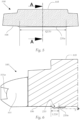
- the Figure 1, 1a and 2 show a lighting device 1 for a motor vehicle headlight for generating a light distribution LV with a cut-off line HDG, wherein the light distributions that can be generated with this lighting device 1 in Figures 7 and 8 are shown schematically, where Figure 8 shows a light distribution as a simulation result using a lighting device according to the invention.
- FIG 2a shows an alternative embodiment of a lighting device 1 according to the invention.
- the same reference numerals as in the Figures 1, 1a and 2 denote the same elements.
- a lighting device 1 according to Figure 1, 1a and 2 or according to Figure 2a comprises a light source 10, a translucent body 100, a light coupling element 101 for coupling light into the translucent body 100, which light source 10 emits, and a projection device 500, wherein the projection device 500 has a focal surface or Petzval surface P500.
- the projection device 500 is typically implemented in the form of a projection lens, but can also have a more complex structure in the form of a lens system.
- the Petzval surface P500 also contains the focal line of the projection device 500, on which - in a horizontal plane - the focal points of the projection device 500 lie.
- the light-transmissive body 100 and the light-coupling element 101 are formed integrally and preferably from the same material.
- the projection device 500 is preferably formed separately from these elements 100, 101.
- Body 100, Light coupling element 101 and projection device 500 can be formed from the same material.
- the transparent, translucent material from which the bodies 100, 101, 500 can be formed has a refractive index greater than that of air.
- the material contains, for example, PMMA (polymethyl methacrylate) or PC (polycarbonate) and is particularly preferably formed therefrom.
- the bodies can also be made of glass material, in particular inorganic glass material.
- Light S10 ( Figure 2 , 2a ), which the light source 10 emits, is coupled into the translucent body 100 via a light entry surface 101a of the translucent body 100.
- the coupling element 101 can, for example, have the form of an imaging or non-imaging collimator optic.
- the light coupling surface 101a is designed accordingly in each case; the planar light coupling surface 101a shown or indicated in the figures is merely one of several possible designs for the light coupling surface 101a, which are known per se.
- the light source or, in general, the at least one light source is, for example, one or more light-emitting elements, e.g., one or more LEDs, which are comprised by the light source or the at least one light source.
- the translucent body 100 is delimited, among other things, by an upper boundary surface 105 and a lower boundary surface 106 opposite the upper boundary surface 105, as well as by a light exit surface 102, 102" opposite the light entry surface 101a.
- the coupled-in light of the light source 10 propagates in the light-transmissive body 100 essentially in the direction of the light exit surface 102 as the first light beam S1, wherein the light coupling element 101 forms the light emitted by the light source 10 and coupled into the light coupling element 101 into the first light beam S1.
- the coupled light moves partly without deflection, partly as a result of total reflection at boundary surfaces, especially at the upper Boundary surface 105 and/or lower boundary surface 106 in the translucent body 100 as light beam S1 in the direction of the light exit surface 102.
- the light-transmissive body 100 has a diaphragm edge 104, which is arranged in the light propagation direction between the light coupling element 101 and the projection device 500, wherein the diaphragm edge 104 is imaged in the light distribution LV as a cut-off line HDG (see Figure 7 and Figure 8 ).
- the aperture edge 104 is responsible for modifying the first light beam S1 into the second light beam S2 emerging from the translucent body 100 in such a way that the light distribution LV generated by the projection device 500 from the light rays of the light beam S2 has a cut-off line HDG.
- the shape of the cut-off line in the light distribution LV is determined by the shape and contour of the aperture edge 104.
- the aperture edge 104 is formed by the light exit surface 102 and the lower boundary surface 106, i.e. the two surfaces 102, 106 converge in the aperture edge 104.
- the light coupling element 101 and the light-transmitting body 100 are shaped such that the first light beam S1 is directed in the direction of the light exit surface 102, but preferably mainly into a region P0, in particular a region, preferably just above, the diaphragm edge 104, resulting in a sharp cut-off line HDG with a high illuminance in the light distribution LV below the cut-off line.
- the diaphragm edge 104 is curved in the horizontal direction, in particular concavely curved, and preferably follows the focal point line F500 of the projection device 500 in the diaphragm edge 104.
- the aperture edge 104 is located in or approximately in the Petzval surface P500 of the projection device 500, as already explained in the introduction.
- the light exit surface 102 may be convex in the vertical direction. In this embodiment shown, the light exit surface 102 is thus inclined, starting from the diaphragm edge 104, away from the Petzval surface P500, toward the light source 10.
- the generated light distribution LV is somewhat blurred, ie, the generated light distribution is more homogeneous, and the height of the projection device 500 can be reduced.
- the light exit surface 102" is concave in the horizontal direction and preferably follows the shape of the Petzval surface P500 of the projection device 500.
- the light rays propagating to the light exit surface 102, 102" and exiting the body 100 via this surface are modified by the light-conducting body 100, in particular also by the diaphragm edge 104, into a second light beam S2, which is imaged by the projection device 500 as a light distribution LV with the cut-off line HDG.
- optical coupling-out structures 210, 220 are designed such that light of the first light beam S1, which strikes an optical coupling-out structure 210, 220, exits the light-transmissive body 100.
- the light emerging from the first optical coupling structures 210 propagates in the form of a third light beam S3 outside the light-transmissive body 100 to the projection device 500.
- the light emerging from the second optical coupling structure 220 propagates in the form of a fourth light beam S4 outside the light-transmissive body 100 to the projection device 500.
- the second optical coupling-out structure 220 is further away from the focal surface P500 than the first optical coupling-out structures 210.
- the arrangement is such that the third and fourth light beams S3, S4 impinge directly, ie without prior re-entry into the light-transmitting body 100, onto the projection device 500 and are projected by the latter as signlight light beams S3', S4' into an area B lying above the cut-off line HDG and together form a signlight light distribution SV, wherein the two signlight light beams S 3 ', S 4 ' are imaged into different sub-areas B1, B2 of the area B lying above the cut-off line HDG.
- Light S4 which originates from the coupling-out structure 220 further away from the focal surface P500, produces a blurred or less sharp image due to the (strongly) defocused position and thus a better homogeneity with approximately the same illuminance in the generated light distribution SV4 compared to the light distribution SV3 generated by the light rays S3 of the first coupling-out structures 210 arranged closer to the focal surface P500.
- the light distribution SV4 which is generated by the coupling-out structure 220 further away from the focal surface P500, forms a type of "basic" signlight distribution, which, for example, meets the requirements for a signlight light distribution according to ECE.
- the other light distribution SV3 forms a type of "additional" signlight light distribution, with which further requirements for the signlight that go beyond ECE can be met and/or allows the "basic" signlight light distribution SV4 to be modified, for example, with regard to the generated illuminance, so that certain required limit values are achieved, together with the additional signlight light distribution SV3.
- a signlight light distribution SV can be generated, in particular one that complies with laws or regulations.
- the third and fourth light beams S3, S4 impinge on the projection device 500 in different regions P1, P2 of the projection device 500, in particular below an optical axis X of the projection device 500, and pass through the projection device 500, wherein these regions of the projection device 500 project the third and fourth light beams S3, S4 as signlight light beams S3', S4' into the region B lying above the cut-off line HDG and, for example, form the signlight light distribution SV, wherein the two signlight light beams S3', S4' are imaged as described in different sub-regions B1, B2 of the region B lying above the cut-off line HDG.
- the first or the first optical output coupling structure 210 and the second optical output coupling structure 220 are preferably designed and arranged such that the third and fourth light beams S3, S4 impinge on the projection device 500 or in a region P1, P2 of the projection device 500 such that the partial regions B1, B2, into which the emerging signlight light beams S3', S4' are projected by the projection device 500, either partially overlap, or at least adjoin one another in a section, or are spaced apart from one another.
- Figure 8 shows example simulation results.
- Partial area B1 is offset to the right with respect to the vertical 0° axis just above the cut-off line and is comparatively concentrated, while the upper partial area B2 runs symmetrically to the vertical 0° axis and is significantly less concentrated than partial area B1, i.e. it extends over a significantly larger angular range in both the horizontal and vertical directions.
- the upper edge of partial area B1 merges with the lower edge of partial area B2.
- the first optical coupling-out structures 210 are formed as an elevation on the light-transmissive body 100, specifically on the underside 106, and the second optical coupling-out structure 220 is formed as an elevation on the translucent body 100, again on the underside 106.
- the Figure 7 and Figure 8 The signlight light distributions SV3, SV4 shown (with significantly different horizontal extensions) are achieved by the first and second optical coupling structures 210, 220, as shown in Figure 1a As can be seen, they have a different transverse extension Q 210 , Q 220 , wherein the first coupling-out structure 210 located closer to the light exit surface 102 has a smaller transverse extension Q 210 than the second coupling-out structure Q 220 . In this way, the amount of light emerging from the coupling-out structures can be controlled.
- the second coupling-out structure 220 is arranged symmetrically with respect to the optical axis X, while the first coupling-out structure 210 is shifted to the left with respect to the optical axis X and is preferably located completely to the left of the optical axis X.
- the second coupling-out structure 220 extends continuously from left to right over substantially the entire width of the light-transmitting or light-conducting body 100, the extension on both sides of the optical axis X is identical.
- the (partial) signlight light distribution SV4 of the light bundles S4 is symmetrical with respect to a vertical 0°-0° line (V-V line) in the light image
- the transverse direction in which the first and second optical coupling-out structures 210, 220 extend runs substantially normal to the optical axis X of the projection device 500 and substantially horizontally.
- output coupling structures 210, 220 are preferably each configured approximately in the shape of an output coupling prism, as shown.
- the output coupling prisms each have an exit surface 210a, 220a, which is inclined such that the exiting light beams S3, S4 are directed into the region(s) P1, P2 of the projection device 500, which project the third and fourth light beams S3, S4 and the signlight light beams S3', S4' into the region B located above the cut-off line HDG.
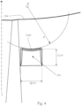
- the exit surfaces 210a, 220a are curved horizontally, ie in horizontal sections, in particular concavely curved, wherein preferably horizontal cutting curves resulting from intersecting such a curved exit surface 210a, 220a with horizontal planes each have the shape of a partial circle or follow the shape of the Petzval surface of the projection device.
- Figure 4 shows a selected section curve in a horizontal section plane, wherein the section curve represents a partial circle with center point M and radius R.
- the section curves can have identical radii, and the center points lie one above the other in a (vertical) line; however, it can also be provided that the radii are different in different horizontal section planes; in particular, it can be provided that the radii increase when moving from the outermost horizontal section plane toward the body 100.
- the center points preferably lie on a vertical line, and the partial circles in different horizontal section planes are thus, as it were, "concentric" partial circles.
- the two exit surfaces 210a, 220a are not curved.
- the intersection curves resulting from the intersection of the exit surfaces 210a, 220a with vertical planes are thus straight lines.
- the exit surfaces 210a, 220a are inclined to the optical axis X by an angle such that the passing through or exiting S 3 , S 4 run orthogonally to the flat entry surface 210a, 220a.
Landscapes
- Engineering & Computer Science (AREA)
- General Engineering & Computer Science (AREA)
- Physics & Mathematics (AREA)
- Optics & Photonics (AREA)
- Microelectronics & Electronic Packaging (AREA)
- General Physics & Mathematics (AREA)
- Non-Portable Lighting Devices Or Systems Thereof (AREA)
Priority Applications (5)
| Application Number | Priority Date | Filing Date | Title |
|---|---|---|---|
| EP23205834.7A EP4545845B1 (fr) | 2023-10-25 | 2023-10-25 | Dispositif d'éclairage pour un phare de véhicule automobile et phare de véhicule automobile |
| KR1020240140446A KR20250060098A (ko) | 2023-10-25 | 2024-10-15 | 자동차 헤드라이트용 조명 장치 및 자동차 헤드라이트 |
| JP2024181411A JP7771327B2 (ja) | 2023-10-25 | 2024-10-17 | 自動車投光器用の照射装置並びに自動車投光器 |
| US18/921,790 US12467596B2 (en) | 2023-10-25 | 2024-10-21 | Illumination device for a motor vehicle headlight and motor vehicle headlight |
| CN202411491271.1A CN119879117A (zh) | 2023-10-25 | 2024-10-24 | 用于机动车辆前照灯的照明装置以及机动车辆前照灯 |
Applications Claiming Priority (1)
| Application Number | Priority Date | Filing Date | Title |
|---|---|---|---|
| EP23205834.7A EP4545845B1 (fr) | 2023-10-25 | 2023-10-25 | Dispositif d'éclairage pour un phare de véhicule automobile et phare de véhicule automobile |
Publications (2)
| Publication Number | Publication Date |
|---|---|
| EP4545845A1 true EP4545845A1 (fr) | 2025-04-30 |
| EP4545845B1 EP4545845B1 (fr) | 2026-04-08 |
Family
ID=88510803
Family Applications (1)
| Application Number | Title | Priority Date | Filing Date |
|---|---|---|---|
| EP23205834.7A Active EP4545845B1 (fr) | 2023-10-25 | 2023-10-25 | Dispositif d'éclairage pour un phare de véhicule automobile et phare de véhicule automobile |
Country Status (5)
| Country | Link |
|---|---|
| US (1) | US12467596B2 (fr) |
| EP (1) | EP4545845B1 (fr) |
| JP (1) | JP7771327B2 (fr) |
| KR (1) | KR20250060098A (fr) |
| CN (1) | CN119879117A (fr) |
Citations (6)
| Publication number | Priority date | Publication date | Assignee | Title |
|---|---|---|---|---|
| JP2014203587A (ja) * | 2013-04-02 | 2014-10-27 | 市光工業株式会社 | 車両用灯具 |
| JP2017084556A (ja) * | 2015-10-27 | 2017-05-18 | スタンレー電気株式会社 | レンズ体、レンズ結合体及び車両用灯具 |
| WO2018023141A1 (fr) * | 2016-08-04 | 2018-02-08 | Zkw Group Gmbh | Projecteur de véhicule automobile |
| EP4067734A1 (fr) * | 2019-11-27 | 2022-10-05 | Ichikoh Industries, Ltd. | Corps de guidage de lumière de véhicule et unité de lampe de véhicule |
| CN115183196A (zh) * | 2022-05-24 | 2022-10-14 | 马瑞利汽车零部件(芜湖)有限公司 | 配光镜系统及车灯模组系统 |
| WO2023038010A1 (fr) * | 2021-09-08 | 2023-03-16 | 市光工業株式会社 | Corps de guidage de lumière de véhicule et unité d'éclairage de véhicule |
Family Cites Families (6)
| Publication number | Priority date | Publication date | Assignee | Title |
|---|---|---|---|---|
| TWI607181B (zh) | 2015-07-06 | 2017-12-01 | 隆達電子股份有限公司 | 導光柱與使用其的車用燈具 |
| CN106439672B (zh) | 2016-08-17 | 2019-01-15 | 上海小糸车灯有限公司 | 一种led光源车灯模组 |
| EP3643962A1 (fr) | 2018-10-25 | 2020-04-29 | ZKW Group GmbH | Unité d'éclairage pour un phare de véhicule automobile |
| JP7268339B2 (ja) | 2018-12-05 | 2023-05-08 | 市光工業株式会社 | 車両用導光体、光源ユニット及び車両用前照灯 |
| WO2020233297A1 (fr) | 2019-05-20 | 2020-11-26 | 华域视觉科技(上海)有限公司 | Ensemble d'éléments optiques de lampe de véhicule, module d'éclairage de véhicule, lampe de véhicule et véhicule |
| DE102021113978B4 (de) * | 2021-05-31 | 2023-03-16 | HELLA GmbH & Co. KGaA | Beleuchtungsmodul und Beleuchtungsverfahren zum Erzeugen zweier unterschiedlicher Leuchtbilder |
-
2023
- 2023-10-25 EP EP23205834.7A patent/EP4545845B1/fr active Active
-
2024
- 2024-10-15 KR KR1020240140446A patent/KR20250060098A/ko active Pending
- 2024-10-17 JP JP2024181411A patent/JP7771327B2/ja active Active
- 2024-10-21 US US18/921,790 patent/US12467596B2/en active Active
- 2024-10-24 CN CN202411491271.1A patent/CN119879117A/zh active Pending
Patent Citations (6)
| Publication number | Priority date | Publication date | Assignee | Title |
|---|---|---|---|---|
| JP2014203587A (ja) * | 2013-04-02 | 2014-10-27 | 市光工業株式会社 | 車両用灯具 |
| JP2017084556A (ja) * | 2015-10-27 | 2017-05-18 | スタンレー電気株式会社 | レンズ体、レンズ結合体及び車両用灯具 |
| WO2018023141A1 (fr) * | 2016-08-04 | 2018-02-08 | Zkw Group Gmbh | Projecteur de véhicule automobile |
| EP4067734A1 (fr) * | 2019-11-27 | 2022-10-05 | Ichikoh Industries, Ltd. | Corps de guidage de lumière de véhicule et unité de lampe de véhicule |
| WO2023038010A1 (fr) * | 2021-09-08 | 2023-03-16 | 市光工業株式会社 | Corps de guidage de lumière de véhicule et unité d'éclairage de véhicule |
| CN115183196A (zh) * | 2022-05-24 | 2022-10-14 | 马瑞利汽车零部件(芜湖)有限公司 | 配光镜系统及车灯模组系统 |
Also Published As
| Publication number | Publication date |
|---|---|
| US20250137604A1 (en) | 2025-05-01 |
| CN119879117A (zh) | 2025-04-25 |
| KR20250060098A (ko) | 2025-05-07 |
| EP4545845B1 (fr) | 2026-04-08 |
| US12467596B2 (en) | 2025-11-11 |
| JP7771327B2 (ja) | 2025-11-17 |
| JP2025073088A (ja) | 2025-05-12 |
Similar Documents
| Publication | Publication Date | Title |
|---|---|---|
| EP2799761B1 (fr) | Module d'éclairage de phare de véhicule automobile | |
| EP3449178B1 (fr) | Dispositif d'illumination pour phare de véhicule avec une distribution de lumière ayant une coupure | |
| AT518552B1 (de) | Beleuchtungseinheit für einen Kraftfahrzeugscheinwerfer zum Erzeugen von zumindest zwei Lichtverteilungen | |
| DE602004002043T2 (de) | Elliptische Beleuchtungseinheit ohne Lichtblende zur Erzeugung eines Abblendlichtbündels und Scheinwerfer mit einer derartigen Belleuchtungseinheit | |
| DE3932273C2 (de) | Fahrzeugscheinwerfer mit einem Reflektor mit mehrteilig augebildeter Reflexionsfläche | |
| DE102014205994B4 (de) | Lichtmodul mit Halbleiterlichtquelle und Vorsatzoptik und Kraftfahrzeugscheinwerfer mit einem solchen Lichtmodul | |
| DE102011078653B4 (de) | Vorsatzoptik zur Bündelung von ausgesandtem Licht mindestens einer Halbleiterlichtquelle | |
| EP3653926B1 (fr) | Dispositif d'éclairage pour un phare de véhicule automobile ainsi que phare de véhicule automobile | |
| DE102012213845A1 (de) | Lichtleitelement und Lichtmodul | |
| WO2018023141A1 (fr) | Projecteur de véhicule automobile | |
| EP3388734B1 (fr) | Unité optique primaire pour un module d'éclairage de phare de véhicule | |
| DE202014010486U1 (de) | Lichtleiter mit horizontaler Hell-Dunkel-Grenze und horizontaler Streuung | |
| DE102006033920A1 (de) | Fahrzeugleuchte | |
| EP3861242B1 (fr) | Dispositif d'éclairage pour un phare de véhicule automobile | |
| EP2984396A2 (fr) | Unité lumineuse dotée d'un cache pourvu d'au moins une fenêtre optique | |
| EP3899358A1 (fr) | Dispositif d'éclairage pour un phare de véhicule automobile ainsi que phare de véhicule automobile | |
| EP2963334A2 (fr) | Système de conducteurs lumineux utilisé dans un dispositif d'éclairage d'un véhicule automobile et dispositif d'éclairage de véhicule automobile doté d'un tel système de conducteurs lumineux | |
| EP4202289B1 (fr) | Système optique pour un phare de véhicule automobile | |
| DE102015207960A1 (de) | Plattenförmiges Lichtleiterelement zum Einsatz in einer Beleuchtungseinrichtung eines Kraftfahrzeugs und Beleuchtungseinrichtung mit einem solchen Lichtleiterelement | |
| EP4545845B1 (fr) | Dispositif d'éclairage pour un phare de véhicule automobile et phare de véhicule automobile | |
| EP4506616B1 (fr) | Dispositif d'éclairage pour un phare de véhicule automobile et phare de véhicule automobile | |
| DE69118153T2 (de) | KFZ-Scheinwerfer mit Lichtleitern | |
| EP4273440B1 (fr) | Module d'éclairage doté de plusieurs éléments optiques auxiliaires | |
| EP4621285A1 (fr) | Dispositif d'éclairage pour véhicule automobile | |
| WO2020083601A1 (fr) | Unité d'éclairage pour projecteur de véhicule automobile |
Legal Events
| Date | Code | Title | Description |
|---|---|---|---|
| PUAI | Public reference made under article 153(3) epc to a published international application that has entered the european phase |
Free format text: ORIGINAL CODE: 0009012 |
|
| STAA | Information on the status of an ep patent application or granted ep patent |
Free format text: STATUS: THE APPLICATION HAS BEEN PUBLISHED |
|
| AK | Designated contracting states |
Kind code of ref document: A1 Designated state(s): AL AT BE BG CH CY CZ DE DK EE ES FI FR GB GR HR HU IE IS IT LI LT LU LV MC ME MK MT NL NO PL PT RO RS SE SI SK SM TR |
|
| STAA | Information on the status of an ep patent application or granted ep patent |
Free format text: STATUS: REQUEST FOR EXAMINATION WAS MADE |
|
| 17P | Request for examination filed |
Effective date: 20250917 |
|
| GRAP | Despatch of communication of intention to grant a patent |
Free format text: ORIGINAL CODE: EPIDOSNIGR1 |
|
| STAA | Information on the status of an ep patent application or granted ep patent |
Free format text: STATUS: GRANT OF PATENT IS INTENDED |
|
| GRAS | Grant fee paid |
Free format text: ORIGINAL CODE: EPIDOSNIGR3 |
|
| GRAA | (expected) grant |
Free format text: ORIGINAL CODE: 0009210 |
|
| STAA | Information on the status of an ep patent application or granted ep patent |
Free format text: STATUS: THE PATENT HAS BEEN GRANTED |
|
| RIC1 | Information provided on ipc code assigned before grant |
Ipc: F21S 41/143 20180101AFI20260202BHEP Ipc: F21S 41/24 20180101ALI20260202BHEP Ipc: F21S 41/25 20180101ALI20260202BHEP Ipc: F21S 41/32 20180101ALI20260202BHEP Ipc: F21S 41/27 20180101ALI20260202BHEP |
|
| INTG | Intention to grant announced |
Effective date: 20260212 |
|
| AK | Designated contracting states |
Kind code of ref document: B1 Designated state(s): AL AT BE BG CH CY CZ DE DK EE ES FI FR GB GR HR HU IE IS IT LI LT LU LV MC ME MK MT NL NO PL PT RO RS SE SI SK SM TR |
|
| REG | Reference to a national code |
Ref country code: CH Ref legal event code: F10 Free format text: ST27 STATUS EVENT CODE: U-0-0-F10-F00 (AS PROVIDED BY THE NATIONAL OFFICE) Effective date: 20260408 Ref country code: GB Ref legal event code: FG4D Free format text: NOT ENGLISH |
|
| REG | Reference to a national code |
Ref country code: DE Ref legal event code: R096 Ref document number: 502023003666 Country of ref document: DE |