EP4545849A1 - Plaque transparente avec un dispositif de maintien pour fibres optiques - Google Patents
Plaque transparente avec un dispositif de maintien pour fibres optiques Download PDFInfo
- Publication number
- EP4545849A1 EP4545849A1 EP23205571.5A EP23205571A EP4545849A1 EP 4545849 A1 EP4545849 A1 EP 4545849A1 EP 23205571 A EP23205571 A EP 23205571A EP 4545849 A1 EP4545849 A1 EP 4545849A1
- Authority
- EP
- European Patent Office
- Prior art keywords
- recess
- optical fiber
- pane
- holding
- light
- Prior art date
- Legal status (The legal status is an assumption and is not a legal conclusion. Google has not performed a legal analysis and makes no representation as to the accuracy of the status listed.)
- Withdrawn
Links
Images


Classifications
-
- F—MECHANICAL ENGINEERING; LIGHTING; HEATING; WEAPONS; BLASTING
- F21—LIGHTING
- F21S—NON-PORTABLE LIGHTING DEVICES; SYSTEMS THEREOF; VEHICLE LIGHTING DEVICES SPECIALLY ADAPTED FOR VEHICLE EXTERIORS
- F21S41/00—Illuminating devices specially adapted for vehicle exteriors, e.g. headlamps
- F21S41/20—Illuminating devices specially adapted for vehicle exteriors, e.g. headlamps characterised by refractors, transparent cover plates, light guides or filters
- F21S41/24—Light guides
-
- G—PHYSICS
- G02—OPTICS
- G02B—OPTICAL ELEMENTS, SYSTEMS OR APPARATUS
- G02B6/00—Light guides; Structural details of arrangements comprising light guides and other optical elements, e.g. couplings
- G02B6/0001—Light guides; Structural details of arrangements comprising light guides and other optical elements, e.g. couplings specially adapted for lighting devices or systems
- G02B6/0005—Light guides; Structural details of arrangements comprising light guides and other optical elements, e.g. couplings specially adapted for lighting devices or systems the light guides being of the fibre type
- G02B6/001—Light guides; Structural details of arrangements comprising light guides and other optical elements, e.g. couplings specially adapted for lighting devices or systems the light guides being of the fibre type the light being emitted along at least a portion of the lateral surface of the fibre
-
- F—MECHANICAL ENGINEERING; LIGHTING; HEATING; WEAPONS; BLASTING
- F21—LIGHTING
- F21S—NON-PORTABLE LIGHTING DEVICES; SYSTEMS THEREOF; VEHICLE LIGHTING DEVICES SPECIALLY ADAPTED FOR VEHICLE EXTERIORS
- F21S41/00—Illuminating devices specially adapted for vehicle exteriors, e.g. headlamps
- F21S41/20—Illuminating devices specially adapted for vehicle exteriors, e.g. headlamps characterised by refractors, transparent cover plates, light guides or filters
- F21S41/2805—Cover glass
-
- F—MECHANICAL ENGINEERING; LIGHTING; HEATING; WEAPONS; BLASTING
- F21—LIGHTING
- F21S—NON-PORTABLE LIGHTING DEVICES; SYSTEMS THEREOF; VEHICLE LIGHTING DEVICES SPECIALLY ADAPTED FOR VEHICLE EXTERIORS
- F21S41/00—Illuminating devices specially adapted for vehicle exteriors, e.g. headlamps
- F21S41/20—Illuminating devices specially adapted for vehicle exteriors, e.g. headlamps characterised by refractors, transparent cover plates, light guides or filters
- F21S41/29—Attachment thereof
-
- F—MECHANICAL ENGINEERING; LIGHTING; HEATING; WEAPONS; BLASTING
- F21—LIGHTING
- F21S—NON-PORTABLE LIGHTING DEVICES; SYSTEMS THEREOF; VEHICLE LIGHTING DEVICES SPECIALLY ADAPTED FOR VEHICLE EXTERIORS
- F21S43/00—Signalling devices specially adapted for vehicle exteriors, e.g. brake lamps, direction indicator lights or reversing lights
- F21S43/20—Signalling devices specially adapted for vehicle exteriors, e.g. brake lamps, direction indicator lights or reversing lights characterised by refractors, transparent cover plates, light guides or filters
- F21S43/235—Light guides
- F21S43/236—Light guides characterised by the shape of the light guide
- F21S43/237—Light guides characterised by the shape of the light guide rod-shaped
-
- F—MECHANICAL ENGINEERING; LIGHTING; HEATING; WEAPONS; BLASTING
- F21—LIGHTING
- F21S—NON-PORTABLE LIGHTING DEVICES; SYSTEMS THEREOF; VEHICLE LIGHTING DEVICES SPECIALLY ADAPTED FOR VEHICLE EXTERIORS
- F21S43/00—Signalling devices specially adapted for vehicle exteriors, e.g. brake lamps, direction indicator lights or reversing lights
- F21S43/20—Signalling devices specially adapted for vehicle exteriors, e.g. brake lamps, direction indicator lights or reversing lights characterised by refractors, transparent cover plates, light guides or filters
- F21S43/235—Light guides
- F21S43/242—Light guides characterised by the emission area
- F21S43/245—Light guides characterised by the emission area emitting light from one or more of its major surfaces
-
- F—MECHANICAL ENGINEERING; LIGHTING; HEATING; WEAPONS; BLASTING
- F21—LIGHTING
- F21S—NON-PORTABLE LIGHTING DEVICES; SYSTEMS THEREOF; VEHICLE LIGHTING DEVICES SPECIALLY ADAPTED FOR VEHICLE EXTERIORS
- F21S43/00—Signalling devices specially adapted for vehicle exteriors, e.g. brake lamps, direction indicator lights or reversing lights
- F21S43/20—Signalling devices specially adapted for vehicle exteriors, e.g. brake lamps, direction indicator lights or reversing lights characterised by refractors, transparent cover plates, light guides or filters
- F21S43/265—Transparent cover plates, e.g. for protecting the interior of the signalling devices against environmental influences
-
- F—MECHANICAL ENGINEERING; LIGHTING; HEATING; WEAPONS; BLASTING
- F21—LIGHTING
- F21S—NON-PORTABLE LIGHTING DEVICES; SYSTEMS THEREOF; VEHICLE LIGHTING DEVICES SPECIALLY ADAPTED FOR VEHICLE EXTERIORS
- F21S43/00—Signalling devices specially adapted for vehicle exteriors, e.g. brake lamps, direction indicator lights or reversing lights
- F21S43/20—Signalling devices specially adapted for vehicle exteriors, e.g. brake lamps, direction indicator lights or reversing lights characterised by refractors, transparent cover plates, light guides or filters
- F21S43/27—Attachment thereof
-
- F—MECHANICAL ENGINEERING; LIGHTING; HEATING; WEAPONS; BLASTING
- F21—LIGHTING
- F21V—FUNCTIONAL FEATURES OR DETAILS OF LIGHTING DEVICES OR SYSTEMS THEREOF; STRUCTURAL COMBINATIONS OF LIGHTING DEVICES WITH OTHER ARTICLES, NOT OTHERWISE PROVIDED FOR
- F21V17/00—Fastening of component parts of lighting devices, e.g. shades, globes, refractors, reflectors, filters, screens, grids or protective cages
- F21V17/10—Fastening of component parts of lighting devices, e.g. shades, globes, refractors, reflectors, filters, screens, grids or protective cages characterised by specific fastening means or way of fastening
-
- G—PHYSICS
- G02—OPTICS
- G02B—OPTICAL ELEMENTS, SYSTEMS OR APPARATUS
- G02B6/00—Light guides; Structural details of arrangements comprising light guides and other optical elements, e.g. couplings
- G02B6/0001—Light guides; Structural details of arrangements comprising light guides and other optical elements, e.g. couplings specially adapted for lighting devices or systems
- G02B6/0011—Light guides; Structural details of arrangements comprising light guides and other optical elements, e.g. couplings specially adapted for lighting devices or systems the light guides being planar or of plate-like form
- G02B6/0081—Mechanical or electrical aspects of the light guide and light source in the lighting device peculiar to the adaptation to planar light guides, e.g. concerning packaging
- G02B6/0095—Light guides as housings, housing portions, shelves, doors, tiles, windows, or the like
-
- B—PERFORMING OPERATIONS; TRANSPORTING
- B60—VEHICLES IN GENERAL
- B60Q—ARRANGEMENT OF SIGNALLING OR LIGHTING DEVICES, THE MOUNTING OR SUPPORTING THEREOF OR CIRCUITS THEREFOR, FOR VEHICLES IN GENERAL
- B60Q2900/00—Features of lamps not covered by other groups in B60Q
- B60Q2900/50—Arrangements to reconfigure features of lighting or signalling devices, or to choose from a list of pre-defined settings
-
- F—MECHANICAL ENGINEERING; LIGHTING; HEATING; WEAPONS; BLASTING
- F21—LIGHTING
- F21V—FUNCTIONAL FEATURES OR DETAILS OF LIGHTING DEVICES OR SYSTEMS THEREOF; STRUCTURAL COMBINATIONS OF LIGHTING DEVICES WITH OTHER ARTICLES, NOT OTHERWISE PROVIDED FOR
- F21V2200/00—Use of light guides, e.g. fibre optic devices, in lighting devices or systems
- F21V2200/10—Use of light guides, e.g. fibre optic devices, in lighting devices or systems of light guides of the optical fibres type
-
- F—MECHANICAL ENGINEERING; LIGHTING; HEATING; WEAPONS; BLASTING
- F21—LIGHTING
- F21W—INDEXING SCHEME ASSOCIATED WITH SUBCLASSES F21K, F21L, F21S and F21V, RELATING TO USES OR APPLICATIONS OF LIGHTING DEVICES OR SYSTEMS
- F21W2102/00—Exterior vehicle lighting devices for illuminating purposes
-
- F—MECHANICAL ENGINEERING; LIGHTING; HEATING; WEAPONS; BLASTING
- F21—LIGHTING
- F21W—INDEXING SCHEME ASSOCIATED WITH SUBCLASSES F21K, F21L, F21S and F21V, RELATING TO USES OR APPLICATIONS OF LIGHTING DEVICES OR SYSTEMS
- F21W2103/00—Exterior vehicle lighting devices for signalling purposes
Definitions
- the optical fiber In general, it is desirable to position the optical fiber as close as possible to the transparent pane to achieve an optimal lighting effect, which is particularly advantageous when using the optical fiber as a design element.
- positioning is advantageous for optimally achieving so-called "linear” lighting effects, or linear lighting phenomena, which result in light patterns that are large in one direction and small in the transverse direction; narrow, line-like light impressions are created, which, for example, act as contour or design lines.
- optical fibers in conjunction with a transparent pane is not only of interest in the field of automotive lighting, but the use of optical fibers can also be of interest in conjunction with general lighting devices, e.g. lighting devices for illuminating living or working spaces, street lighting, etc., in which a translucent, transparent pane is provided which, for example, closes off a housing of the lighting device.
- general lighting devices e.g. lighting devices for illuminating living or working spaces, street lighting, etc.
- a translucent, transparent pane is provided which, for example, closes off a housing of the lighting device.
- At least one light source is typically provided to realize a basic function of the lighting device, which serves at least one optical fiber - using at least one additional light source - to realize an additional light function, for example to realize a design light.
- the holding device is attached to the inner surface of the plate body and the holding device has at least one recess which extends over a length along the inner surface and substantially parallel to the inner surface, wherein the at least one recess is open in a region facing away from the plate body, so that at least one optical fiber can be inserted into the at least one recess from a side facing away from the inner surface of the plate body, and wherein holding means are further provided with which the at least one optical fiber arranged in the at least one recess can be held.
- a holding device is provided on the inner surface of the disc body, in particular in the form of a structure protruding from the inside, which preferably projects as slightly as possible into the housing. With this holding device one or more optical fibers can be held close to the cover plate or the plate body.
- the holding device is made of the same material as the disc body.
- the holding device is formed integrally with the disc body.
- the holding device is designed to protrude from the inner surface of the disc body, in particular to protrude vertically.
- the recess is continuous over its length or has one or more interruptions.
- the recess extends continuously over almost the entire length of the optical fiber, at least over that length of the optical fiber arranged in the region of the disk body.
- the recess has one or more interruptions, in particular because no holding device is provided in the interruption regions and, accordingly, the holding device is divided into two or more separate, spaced-apart regions, each of which contains sections of the recess.
- the holding device is at least partially made of a translucent material.
- these cheeks can also be made of an opaque material, since no light needs to pass through them.
- the cheeks act as shading screens and suppress light crosstalk, especially in the case of parallel light strokes or lines arranged close together, which appear as separate lines due to these shading screens. This allows brightness contrasts or color differences to be more clearly emphasized.
- the recess base is formed by the pane body itself, light can pass through it unhindered. However, if the recess base is formed by an additional material applied to the inner surface of the pane body, this recess base is preferably made of a transparent material.
- the at least one recess is groove-shaped and has groove cheeks projecting from the inner surface of the disc body, preferably running parallel to one another in the longitudinal extent of the at least one recess, and wherein the holding means are formed by the groove cheeks in that the groove cheeks are designed and arranged relative to one another in such a way that they clamp an optical fiber inserted into the at least one groove-shaped recess in the recess.
- the holding device consists, for example, of a holding device body in which the recess is formed in the form of a groove.
- the optical fiber is coated with a transparent, optionally colored sheath, for example, in the form of a transparent tube. Two or more optical fibers can also be coated simultaneously with such a sheath.
- the sheathing can, in particular in the case of an optical fiber, completely enclose it, in particular around the entire circumference; however, it can also be provided that the sheathing is arranged only over part of the circumference of the optical fiber.
- the optical fiber or optical fiber tube embedded in the groove can be clamped directly in the groove.
- the remaining free area in the groove between the groove bottom, groove cheeks and optical fiber or tube can be filled with a filling material, which stabilizes the connection in the groove.
- the material is preferably cured in a suitable manner after insertion.
- the at least one recess is formed by cheeks which protrude from the inner surface of the disc body and preferably run parallel to one another in the longitudinal extent of the at least one recess, and wherein the holding means comprise at least one holding element in which the at least one optical fiber is arranged in a fixed manner, and wherein the at least one holding element is designed such that when the holding element is joined to the holding device, the at least one optical fiber is inserted into the recess, and wherein the holding means further comprise fixing means with which the holding element can be fixed to the holding device.
- the recess can again be groove-shaped.
- the at least one optical fiber is glued to the at least one holding element and/or the holding element has mechanical means for holding the at least one optical fiber.
- the mechanical means can be realized, for example, by providing a recess in the holding element, delimited by two cheeks, for example in the form of a groove, in which recess the optical fiber can be clamped or clipped, or alternatively or additionally is glued in this recess.
- the holding element can be transparent or at least partially made of an opaque material.
- the holding element and the fixing means are designed such that the optical fiber faces the inner surface of the disc body with an exposed optical fiber surface.
- the fixing means comprise adhesive or a mechanical connection between the at least one holding element and the holding device, e.g., a clipping of the at least one holding element to the holding device, or a welded connection between the at least one holding element and the holding device.
- the adhesive can, for example, be liquid silicone, which forms an adhesive bed into which the optical fiber is inserted and which subsequently hardens.
- the at least one recess of cheeks which protrude from the inner surface of the disc body and are preferably parallel to one another in the longitudinal extension of the at least one recess extend, and wherein at least one optical fiber can be inserted into the at least one recess, wherein a height of the cheeks measured from the inner surface of the disc body is such that the at least one optical fiber protrudes from the recess or just does not protrude, and wherein the holding means comprise a film which is foil-wrapped onto the cheeks in such a way that the at least one optical fiber is pressed into the recess, and preferably against the inner surface of the disc body.
- the film serves as an encapsulating agent for encapsulating at least one optical fiber or optical fiber tube in the recess.
- the invention relates to a cover plate system comprising a cover plate according to one of the preceding claims and one or more optical fibers which are held on the plate body by the holding device.
- the lighting device comprises one or more additional light sources which are configured to feed light into the at least one optical fiber which is held on the cover plate.
- the lighting device comprises at least one light source, wherein the lighting device is designed to realize one or more lighting functions with the at least one light source, wherein the transparent pane is in the beam path of the at least one light source such that light emitted by the at least one light source can impinge on the inner surface of the pane body and pass through it.
- the lighting device has a housing which is closed off by the pane, wherein the at least one light source and/or the at least one additional light source is/are arranged in the housing.
- the lighting device is designed as a living room or work room lighting device, for example as a ceiling light or floor lamp, or as a street light, luminous sign or facade exterior lighting device.
- the invention also relates to a motor vehicle lamp, wherein the motor vehicle lamp is designed as a motor vehicle headlight or rear light or is arranged in a motor vehicle headlight or rear light, or is designed as a vehicle interior light or as a vehicle floor projection light, wherein the motor vehicle lamp comprises at least one lighting device as described above.
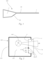
- Figure 1 shows purely schematically the transparent pane in the form of a pane 1, e.g. a cover pane of a lighting device 100 for a motor vehicle, which in this example is specifically shown in the form of a rear light, as well as a linear arrangement of two optical fibers 50 on the cover pane 1.
- a pane 1 e.g. a cover pane of a lighting device 100 for a motor vehicle, which in this example is specifically shown in the form of a rear light, as well as a linear arrangement of two optical fibers 50 on the cover pane 1.
- design effects or a special optical appearance in general or in the case of rear lights or a vehicle headlight, can be realized, which allows the manufacturers of the lighting device, e.g. vehicle manufacturers, to individualize the appearance of their vehicles.
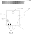
- FIG 2 shows a lighting device 100 in the form of a vehicle headlight in a roughly schematic side view.
- the lighting device 100 has at least one light source 103, which is arranged in a housing 101.
- the housing 101 encloses a housing interior 102, which is closed by a transparent pane 1, the so-called cover pane.
- the disc 1 consists of a disc body 1a, which is bordered by an inner surface 3, which faces the light source 103 or the housing interior, and an outer surface 2, which faces outwards and delimits the lighting device 100 towards the outside space.
- the optical fibers 50 and the optical fiber tube 51 are coupled into the optical fiber 50 and the optical fiber tube 51 with light from at least one additional light source 113, for example from an LED or laser light source, which can be mounted, for example, on a print in the lighting device 100 (for example, on the print on which the light source 103 is arranged).
- a coupling element is often used which connects the optical fiber to the light source like a plug, whereby the connection is typically only established when the cover plate (including the optical fiber) is mounted on the housing of the lighting device 100.
- a homogeneous contour illumination on the cover plate can be generated by the optical fibers 50 or the optical fiber tube 51.
- the pane can be a clear pane, but that the pane can also be designed, at least in some areas, but also completely, e.g. in the manner of frosted glass, in that it is, for example, roughened, colored or tinted in some areas, can have optical structures, and can also have areas that are not translucent, as well as any combination of these possibilities.
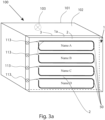
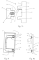
- Figure 3 shows another example of a lighting device 100, in this case a ceiling light for an interior, which is suspended from a ceiling 500 in the interior.
- the lighting device 100 has a housing 101 and a housing interior 102 in which a light source 103 is arranged to implement a desired lighting function.
- a transparent pane 1 Located in the beam path of the light source 103 is a transparent pane 1 comprising a pane body 1a, inner surface 3, and outer surface 2.
- additional light sources 113 are provided for feeding light into optical fibers 50, which are attached to the inner surface 3 of the disc body 1a.
- pane 1 is arranged in the beam path of the (or at least one of the several) light sources 103 of the lighting device 100.
- Figure 3a shows, as a final example, a lighting device 100 in the form of a display panel, in which information "Name A", “Name B”, “Name C”, “Name D” is displayed on or behind a transparent panel 1, and this information is each framed by a light strip in the form of an optical fiber 50.
- Each optical fiber 50 is supplied with light by an additional light source 113, wherein the Additional light sources 113, such as LEDs, can emit colored light, e.g. red, blue, green and amber, so that different color effects can be created.
- NAME A represent placeholder elements for information in any form, be it graphic and/or textual, in the form of pictograms, etc. These placeholder elements can be simple prints that can be applied to/on the outer surface 2 or the inner surface 3.
- the at least one light source 103 illuminates the placeholder elements from the rear, as shown in the figure.
- the lighting device "only” has one or more additional light sources as light sources.
- it can also be a display or a flat screen, so that different, even changing information is shown, in which case several, in particular a large number of, light sources are provided.
- an optical fiber 50 may be coated with a transparent, optionally colored sheath 52, or that such a sheath 52 may also cover two or more optical fibers, as in Figure 5 shown, can simultaneously enclose it, so that a transparent optical fiber tube 51 is formed.
- the enclosing 52 can, particularly in the case of an optical fiber 50, enclose it completely, in particular around the entire circumference; however, it can also be provided that the enclosing is arranged only over part of the circumference of the optical fiber 50.
- FIGS. 5a and 5b now show roughly schematic examples of a pane system 200 according to the invention, which comprises a transparent pane 1 according to the invention and one or, as shown, several optical fibers 50 arranged thereon, as is used in the lighting devices 100 described above.
- the pane 1 comprises, as already described above, a transparent pane body 1a, which has a first surface 2 - referred to as outer surface 2 - and a second surface 3 opposite the first surface 2 - referred to as inner surface 3 - through which surfaces 2, 3 light generated in the lighting device 100 by the light source 103 can escape into the outside space.
- Figures 5a and 5b a view of the inner surface 3 of the disc body 1a of the disc 1, wherein on the inner surface 3 - in this example several - holding devices 10 for holding optical fibers 50 on the disc body 1a are provided.
- the holding devices 10 each have a recess 11 in which the optical fibers 50 are arranged and held.
- the recesses 11 are open in a region facing away from the disk body 1a, so that one or more optical fibers 50 can be inserted into the respective recess 11 from this direction or side.
- the recesses 11 or holding devices 10 extend over a defined length L along the inner surface 3, as in Figure 5b indicated, and run essentially parallel to the inner surface 3.
- the recesses 11 are, as shown, continuous over their length L, but can also have one or more interruptions.
- the recess extends continuously over the entire length of the optical fiber, at least over that length of the optical fiber which is arranged in the region of the disc body.
- the recess has one or more interruptions, in particular because no holding device is provided in the interruption regions and accordingly the holding device is divided into two or several separate, spaced-apart areas, in each of which sections of the depression are located.
- Holding devices 10 can be formed from the same material as the disc body 1a, in particular from a transparent material, and it can be advantageous if the holding device 10 is formed integrally with the disc body 1a.
- the holding devices can also be formed from a non-transparent material if the holding device is designed such that it does not obstruct the light propagation direction of the light emerging from the optical fiber.
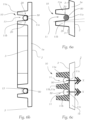
- the (at least one) recess 11 is groove-shaped and is formed or delimited by groove cheeks 11a, 11b that protrude from the inner surface 3 of the disc body 1a, in particular protrude perpendicularly, and preferably run parallel to one another in the longitudinal extension of the recess 11.
- Holding means 20 are provided, with which the optical fiber 50 arranged in the recess 11 is held.
- the holding means 20 are formed by the groove cheeks 11a, 11b, in that the groove cheeks 11a, 11b are designed and arranged relative to one another in such a way that they clamp an optical fiber 50 inserted into the groove-shaped recess 11 in the recess 11.
- the holding device 10 thus consists of a holding device body 10' in which the recess 11 is formed in the form of a groove.
- the groove cheeks 11a, 11b thus form a recess 11 tapering in the direction of the disc body 1a, so that the optical fiber 50, when inserted sufficiently deep into the recess 11, is clamped therein.
- the groove also has a groove base 11c, which faces the inner surface 3.
- the groove base 11c can be straight/flat ( Figure 6b, Figure 6c ) or the cross-sectional shape of the optical fiber 50 corresponding ( Figure 6a ). It can also be provided that the groove cheeks 11a, 11b are formed at a distance from one another on the inner surface 3, so that the groove base 11c is formed by the inner surface 3 of the cover plate itself ( Figure 6b ) so that light can pass directly and unhindered from the holder through the cover plate.
- the groove cheeks 11a, 11b can be parallel, but preferably V-shaped (for example with a draft angle of 0° -10°) or conical, or the cross section of the groove-shaped recess 11 can be dovetail-shaped.
- Figure 6c shows an embodiment in which two recesses 11 "share" a common groove cheeks 11a, 11b, the middle of the groove cheeks shown
- the optical fiber 50 embedded in the groove 11 (or an optical fiber tube 51) can be clamped directly into the groove 11.
- the remaining free area in the groove between the groove bottom, groove sides, and optical fiber 50 or tube 52 can be filled with a filling material, which is preferably transparent, to stabilize the connection in the groove.
- a filling material which is preferably transparent
- the filling material is located only on the back of the optical fiber, or on the back and the side surfaces, or on all four sides including the front side facing the cover plate.
- the filler material is designed to allow unhindered light emission from the optical fiber to the inner and outer surfaces of the cover plate. If an opaque filler material is used, for example, transparent silicone as a liquid, which is introduced into the groove and cured after the optical fiber is inserted, it is preferably provided that only the rear and/or side surfaces of the optical fiber or the light guide tube, i.e., areas facing away from the plate body 1a, are covered.
- an opaque filler material for example, transparent silicone as a liquid, which is introduced into the groove and cured after the optical fiber is inserted, it is preferably provided that only the rear and/or side surfaces of the optical fiber or the light guide tube, i.e., areas facing away from the plate body 1a, are covered.
- an air gap is preferably created between the groove bottom 11c and the optical fiber 50 or the optical fiber tube 51.
- the direction of light emission from the optical fibers is Figure 6c indicated by the direction X.
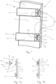
- the Figures 7 and 7a - 7c show a second specific embodiment of the invention.
- the at least one recess 11 is formed by cheeks 11a, 11b, which protrude from the inner surface 3 of the cover plate 1, in particular perpendicularly, and preferably run parallel to one another in the longitudinal extension of the recess 11.
- the recess 11 can again be designed in the form of a groove.
- the holding means 20 comprise a holding element 21 in which the optical fiber 50 is firmly arranged.
- the holding element 21 is designed such that when the holding element 21 is joined to the holding device 10, the optical fiber 50 is inserted into the recess 11. In particular, as shown, a part of the holding element 21 that holds the optical fiber 50 is inserted into the recess 11.
- Figure 7 shows a perspective view of the cover plate
- Figure 7a This shows a state in which a holding element 21 is not yet inserted into the recess 11 in the upper area, while in Figure 7b both holding elements 21 shown are inserted into their associated recesses 11.
- the holding means 20 also comprise fixing means 22 with which the holding element 21 can be fixed to the holding device 10, as will be described further below.
- the optical fiber 50 can be glued to its holding element 21 and/or the holding element 21 has mechanical means for holding the optical fiber 50.
- the mechanical means can be implemented, for example, by providing a recess 60 in the holding element 21, delimited by two cheeks 61, 62, for example in the form of a groove, into which recess 60 the optical fiber 50 can be clamped or clipped, or alternatively or additionally, is glued in this recess.
- Figure 7a and, in enlarged Depiction Figure 7c show such a recess 60 formed by cheeks 61, 62, into which an optical fiber 50 ( Figure 7a ) or an optical fiber tube 51 ( Figure 7c ) is inserted and held.
- the holding element 21 can be transparent, for example colored or non-transparent.
- the holding element 21 and the fixing means 22 are designed such that the optical fiber 50 (the optical fiber tube 51) faces the inner surface 3 of the cover plate 1 with an exposed optical fiber surface 50a (optical fiber tube surface 51a).
- “Exposed” in this context means that the surface 50a, 51a is not covered by the holding element 21.
- the fixing means comprise adhesive means or a mechanical connection between the at least one holding element 21 and the holding device 10, e.g. a clipping of the at least one holding element 21 to the holding device 10, or a welded connection between the at least one holding element 21 and the holding device 10.
- the holding element 21 itself can thus be glued, (laser) welded, or clamped to the holding device 11, for example.
- the holding element 21 can be designed to complement the holding device 10, in particular to the recess 11, so that it is held by it in a form-fitting manner.
- Figure 7c shows a further embodiment of the fixing means 22.
- the fixing means 22 comprise at least one elastically formed Include a spring element 23, which is preferably arranged in the recess 11, and which, when the holding element 21 is inserted into the recess 11, exerts a restoring force on the holding element 21 such that the holding element 21 and thus the optical fiber - or in the example shown an optical fiber tube 51 - is mechanically held in the recess 11.
- the spring element 23 is mounted in the recess 11 on the cheek 11a of the recess 11 and presses on the holding element 21 when the latter is inserted into the recess 11.
- the at least one recess 11 is formed by cheeks 11a, 11b, which protrude from the inner surface 3 of the disc body 1a, in particular perpendicularly, and preferably run parallel to one another in the longitudinal extent of the at least one recess 11, and wherein the height of the cheeks 11a, 11b, measured from the inner surface 3 of the disc body 1a, is such that the at least one optical fiber 50 inserted into the recess 11 protrudes from the recess 11 or just does not protrude, i.e. ends approximately flush with the upper boundary surface 11a', 11b' of the cheeks 11a, 11b.
- the holding means 20 can comprise, for example, a film 70 which is foil-wrapped onto the cheeks 11a, 11b, in particular onto their upper boundary surfaces 11a', 11b', in such a way that the optical fiber 50 is pressed into the recess 11, and preferably against the inner surface 3 of the disc body 1a, or is held against it.
- the film e.g. an adhesive film, is applied to the upper boundary surfaces of the cheeks ("cheek head end surfaces") in such a way that the opening of the recess 11 is closed and the optical fibers are held in the interior.
Landscapes
- Engineering & Computer Science (AREA)
- General Engineering & Computer Science (AREA)
- Physics & Mathematics (AREA)
- General Physics & Mathematics (AREA)
- Optics & Photonics (AREA)
- Optical Couplings Of Light Guides (AREA)
- Light Guides In General And Applications Therefor (AREA)
Priority Applications (2)
| Application Number | Priority Date | Filing Date | Title |
|---|---|---|---|
| EP23205571.5A EP4545849A1 (fr) | 2023-10-24 | 2023-10-24 | Plaque transparente avec un dispositif de maintien pour fibres optiques |
| CN202411478066.1A CN119879115A (zh) | 2023-10-24 | 2024-10-22 | 带有光导纤维保持装置的透明圆盘 |
Applications Claiming Priority (1)
| Application Number | Priority Date | Filing Date | Title |
|---|---|---|---|
| EP23205571.5A EP4545849A1 (fr) | 2023-10-24 | 2023-10-24 | Plaque transparente avec un dispositif de maintien pour fibres optiques |
Publications (1)
| Publication Number | Publication Date |
|---|---|
| EP4545849A1 true EP4545849A1 (fr) | 2025-04-30 |
Family
ID=88511342
Family Applications (1)
| Application Number | Title | Priority Date | Filing Date |
|---|---|---|---|
| EP23205571.5A Withdrawn EP4545849A1 (fr) | 2023-10-24 | 2023-10-24 | Plaque transparente avec un dispositif de maintien pour fibres optiques |
Country Status (2)
| Country | Link |
|---|---|
| EP (1) | EP4545849A1 (fr) |
| CN (1) | CN119879115A (fr) |
Citations (8)
| Publication number | Priority date | Publication date | Assignee | Title |
|---|---|---|---|---|
| US6594417B1 (en) * | 1999-01-14 | 2003-07-15 | Federal-Mogul World Wide, Inc. | Waveguide assembly for laterally-directed illumination in a vehicle lighting system |
| US20090027914A1 (en) * | 2007-07-26 | 2009-01-29 | Chia-Yeh Wu | Structure for a center high mounted stop lamp |
| US20150274066A1 (en) * | 2014-03-28 | 2015-10-01 | GM Global Technology Operations LLC | Vehicle trim panels with interior illumination systems |
| US20150369444A1 (en) * | 2014-06-19 | 2015-12-24 | Toyoda Gosei Co., Ltd. | Waterproof structure for vehicle lighting device |
| DE102017205628A1 (de) | 2017-04-03 | 2018-10-04 | Audi Ag | Fahrzeugaußenflächenbauteil mit darin angeordnetem, längsförmigem, seitlich emittierendem Lichtleiter und Fahrzeug mit dem Fahrzeugaußenflächenbauteil |
| US20200241189A1 (en) * | 2019-01-29 | 2020-07-30 | Schott Ag | Linear lighting device |
| DE102021121783A1 (de) * | 2021-08-23 | 2023-02-23 | Bayerische Motoren Werke Aktiengesellschaft | Bauteil für ein Verkehrsmittel, Verkehrsmittel und Verfahren zur Herstellung des Bauteils |
| DE102021129266A1 (de) * | 2021-11-10 | 2023-05-11 | HELLA GmbH & Co. KGaA | Beleuchtungsvorrichtung für Fahrzeuge |
-
2023
- 2023-10-24 EP EP23205571.5A patent/EP4545849A1/fr not_active Withdrawn
-
2024
- 2024-10-22 CN CN202411478066.1A patent/CN119879115A/zh active Pending
Patent Citations (8)
| Publication number | Priority date | Publication date | Assignee | Title |
|---|---|---|---|---|
| US6594417B1 (en) * | 1999-01-14 | 2003-07-15 | Federal-Mogul World Wide, Inc. | Waveguide assembly for laterally-directed illumination in a vehicle lighting system |
| US20090027914A1 (en) * | 2007-07-26 | 2009-01-29 | Chia-Yeh Wu | Structure for a center high mounted stop lamp |
| US20150274066A1 (en) * | 2014-03-28 | 2015-10-01 | GM Global Technology Operations LLC | Vehicle trim panels with interior illumination systems |
| US20150369444A1 (en) * | 2014-06-19 | 2015-12-24 | Toyoda Gosei Co., Ltd. | Waterproof structure for vehicle lighting device |
| DE102017205628A1 (de) | 2017-04-03 | 2018-10-04 | Audi Ag | Fahrzeugaußenflächenbauteil mit darin angeordnetem, längsförmigem, seitlich emittierendem Lichtleiter und Fahrzeug mit dem Fahrzeugaußenflächenbauteil |
| US20200241189A1 (en) * | 2019-01-29 | 2020-07-30 | Schott Ag | Linear lighting device |
| DE102021121783A1 (de) * | 2021-08-23 | 2023-02-23 | Bayerische Motoren Werke Aktiengesellschaft | Bauteil für ein Verkehrsmittel, Verkehrsmittel und Verfahren zur Herstellung des Bauteils |
| DE102021129266A1 (de) * | 2021-11-10 | 2023-05-11 | HELLA GmbH & Co. KGaA | Beleuchtungsvorrichtung für Fahrzeuge |
Also Published As
| Publication number | Publication date |
|---|---|
| CN119879115A (zh) | 2025-04-25 |
Similar Documents
| Publication | Publication Date | Title |
|---|---|---|
| EP1022187B1 (fr) | Feu de véhicule | |
| AT518118B1 (de) | Beleuchtungseinheit für ein Kraftfahrzeug | |
| DE102004054732B4 (de) | Lichtleiteranordung | |
| DE112014003091T5 (de) | Fahrzeugleuchte | |
| DE102007019688A1 (de) | Signalleuchte für Kraftfahrzeuge | |
| DE102017114476B4 (de) | Beleuchtungseinrichtung eines Kraftfahrzeugs | |
| DE102007036793A1 (de) | Leuchtenvorrichtung für ein Kraftfahrzeug | |
| DE19514424A1 (de) | Zu zwei unterschiedlichen Lichtquellen kompatible Linse für eine Leuchte für ein Fahrzeug | |
| DE20211305U1 (de) | Beleuchtungseinrichtung für ein Kraftfahrzeug mit mehreren Leuchteinheiten | |
| DE102021204889A1 (de) | Beleuchtungsvorrichtung für den Innenraum eines Kraftfahrzeugs | |
| DE102021201145A1 (de) | Kraftfahrzeugscheinwerfer und Verfahren zum Betrieb eines Kraftfahrzeugscheinwerfers | |
| DE102011110629B4 (de) | Beleuchtungsvorrichtung | |
| EP2042802B1 (fr) | Lampe dotée d'un profilé de recouvrement | |
| DE102011050422A1 (de) | Kraftfahrzeugleuchte | |
| DE102021117619A1 (de) | Beleuchtungsvorrichtung für den Außenraum eines Kraftfahrzeugs | |
| EP4545849A1 (fr) | Plaque transparente avec un dispositif de maintien pour fibres optiques | |
| EP2166276B1 (fr) | Agencement de formation d'une source lumineuse longitudinale | |
| DE102021109319A1 (de) | Außenleuchte für ein Kraftfahrzeug | |
| EP3450253B1 (fr) | Dispositif d'éclairage et / ou de signalisation pour un véhicule automobile | |
| WO2017102401A1 (fr) | Dispositif d'éclairage pour un véhicule | |
| DE202023003067U1 (de) | Transparente Scheibe mit einer Haltevorrichtung für Lichtleitfasern | |
| WO2020058236A1 (fr) | Module d'éclairage, notamment destiné à être utilisé dans un dispositif d'éclairage pour véhicule automobile | |
| WO2024083544A1 (fr) | Dispositif d'éclairage pour véhicules | |
| EP2747060B1 (fr) | Éclairage de signalisation | |
| DE102011083368A1 (de) | Fahrzeugleuchte |
Legal Events
| Date | Code | Title | Description |
|---|---|---|---|
| PUAI | Public reference made under article 153(3) epc to a published international application that has entered the european phase |
Free format text: ORIGINAL CODE: 0009012 |
|
| STAA | Information on the status of an ep patent application or granted ep patent |
Free format text: STATUS: THE APPLICATION HAS BEEN PUBLISHED |
|
| AK | Designated contracting states |
Kind code of ref document: A1 Designated state(s): AL AT BE BG CH CY CZ DE DK EE ES FI FR GB GR HR HU IE IS IT LI LT LU LV MC ME MK MT NL NO PL PT RO RS SE SI SK SM TR |
|
| STAA | Information on the status of an ep patent application or granted ep patent |
Free format text: STATUS: THE APPLICATION IS DEEMED TO BE WITHDRAWN |
|
| 18D | Application deemed to be withdrawn |
Effective date: 20251031 |