EP4545899A1 - Mikrokanalwärmetauscher - Google Patents
Mikrokanalwärmetauscher Download PDFInfo
- Publication number
- EP4545899A1 EP4545899A1 EP24205603.4A EP24205603A EP4545899A1 EP 4545899 A1 EP4545899 A1 EP 4545899A1 EP 24205603 A EP24205603 A EP 24205603A EP 4545899 A1 EP4545899 A1 EP 4545899A1
- Authority
- EP
- European Patent Office
- Prior art keywords
- compartments
- tubes
- distributor
- heat exchanger
- header
- Prior art date
- Legal status (The legal status is an assumption and is not a legal conclusion. Google has not performed a legal analysis and makes no representation as to the accuracy of the status listed.)
- Pending
Links
Images





Classifications
-
- F—MECHANICAL ENGINEERING; LIGHTING; HEATING; WEAPONS; BLASTING
- F28—HEAT EXCHANGE IN GENERAL
- F28F—DETAILS OF HEAT-EXCHANGE AND HEAT-TRANSFER APPARATUS, OF GENERAL APPLICATION
- F28F9/00—Casings; Header boxes; Auxiliary supports for elements; Auxiliary members within casings
- F28F9/02—Header boxes; End plates
- F28F9/026—Header boxes; End plates with static flow control means, e.g. with means for uniformly distributing heat exchange media into conduits
- F28F9/027—Header boxes; End plates with static flow control means, e.g. with means for uniformly distributing heat exchange media into conduits in the form of distribution pipes
- F28F9/0273—Header boxes; End plates with static flow control means, e.g. with means for uniformly distributing heat exchange media into conduits in the form of distribution pipes with multiple holes
-
- F—MECHANICAL ENGINEERING; LIGHTING; HEATING; WEAPONS; BLASTING
- F28—HEAT EXCHANGE IN GENERAL
- F28D—HEAT-EXCHANGE APPARATUS, NOT PROVIDED FOR IN ANOTHER SUBCLASS, IN WHICH THE HEAT-EXCHANGE MEDIA DO NOT COME INTO DIRECT CONTACT
- F28D21/00—Heat-exchange apparatus not covered by any of the groups F28D1/00 - F28D20/00
-
- F—MECHANICAL ENGINEERING; LIGHTING; HEATING; WEAPONS; BLASTING
- F28—HEAT EXCHANGE IN GENERAL
- F28D—HEAT-EXCHANGE APPARATUS, NOT PROVIDED FOR IN ANOTHER SUBCLASS, IN WHICH THE HEAT-EXCHANGE MEDIA DO NOT COME INTO DIRECT CONTACT
- F28D1/00—Heat-exchange apparatus having stationary conduit assemblies for one heat-exchange medium only, the media being in contact with different sides of the conduit wall, in which the other heat-exchange medium is a large body of fluid, e.g. domestic or motor car radiators
- F28D1/02—Heat-exchange apparatus having stationary conduit assemblies for one heat-exchange medium only, the media being in contact with different sides of the conduit wall, in which the other heat-exchange medium is a large body of fluid, e.g. domestic or motor car radiators with heat-exchange conduits immersed in the body of fluid
- F28D1/04—Heat-exchange apparatus having stationary conduit assemblies for one heat-exchange medium only, the media being in contact with different sides of the conduit wall, in which the other heat-exchange medium is a large body of fluid, e.g. domestic or motor car radiators with heat-exchange conduits immersed in the body of fluid with tubular conduits
- F28D1/053—Heat-exchange apparatus having stationary conduit assemblies for one heat-exchange medium only, the media being in contact with different sides of the conduit wall, in which the other heat-exchange medium is a large body of fluid, e.g. domestic or motor car radiators with heat-exchange conduits immersed in the body of fluid with tubular conduits the conduits being straight
- F28D1/0535—Heat-exchange apparatus having stationary conduit assemblies for one heat-exchange medium only, the media being in contact with different sides of the conduit wall, in which the other heat-exchange medium is a large body of fluid, e.g. domestic or motor car radiators with heat-exchange conduits immersed in the body of fluid with tubular conduits the conduits being straight the conduits having a non-circular cross-section
- F28D1/05366—Assemblies of conduits connected to common headers, e.g. core type radiators
- F28D1/05391—Assemblies of conduits connected to common headers, e.g. core type radiators with multiple rows of conduits or with multi-channel conduits combined with a particular flow pattern, e.g. multi-row multi-stage radiators
-
- F—MECHANICAL ENGINEERING; LIGHTING; HEATING; WEAPONS; BLASTING
- F25—REFRIGERATION OR COOLING; COMBINED HEATING AND REFRIGERATION SYSTEMS; HEAT PUMP SYSTEMS; MANUFACTURE OR STORAGE OF ICE; LIQUEFACTION SOLIDIFICATION OF GASES
- F25B—REFRIGERATION MACHINES, PLANTS OR SYSTEMS; COMBINED HEATING AND REFRIGERATION SYSTEMS; HEAT PUMP SYSTEMS
- F25B39/00—Evaporators; Condensers
-
- F—MECHANICAL ENGINEERING; LIGHTING; HEATING; WEAPONS; BLASTING
- F25—REFRIGERATION OR COOLING; COMBINED HEATING AND REFRIGERATION SYSTEMS; HEAT PUMP SYSTEMS; MANUFACTURE OR STORAGE OF ICE; LIQUEFACTION SOLIDIFICATION OF GASES
- F25B—REFRIGERATION MACHINES, PLANTS OR SYSTEMS; COMBINED HEATING AND REFRIGERATION SYSTEMS; HEAT PUMP SYSTEMS
- F25B39/00—Evaporators; Condensers
- F25B39/02—Evaporators
- F25B39/028—Evaporators having distributing means
-
- F—MECHANICAL ENGINEERING; LIGHTING; HEATING; WEAPONS; BLASTING
- F25—REFRIGERATION OR COOLING; COMBINED HEATING AND REFRIGERATION SYSTEMS; HEAT PUMP SYSTEMS; MANUFACTURE OR STORAGE OF ICE; LIQUEFACTION SOLIDIFICATION OF GASES
- F25B—REFRIGERATION MACHINES, PLANTS OR SYSTEMS; COMBINED HEATING AND REFRIGERATION SYSTEMS; HEAT PUMP SYSTEMS
- F25B39/00—Evaporators; Condensers
- F25B39/04—Condensers
-
- F—MECHANICAL ENGINEERING; LIGHTING; HEATING; WEAPONS; BLASTING
- F28—HEAT EXCHANGE IN GENERAL
- F28F—DETAILS OF HEAT-EXCHANGE AND HEAT-TRANSFER APPARATUS, OF GENERAL APPLICATION
- F28F9/00—Casings; Header boxes; Auxiliary supports for elements; Auxiliary members within casings
-
- F—MECHANICAL ENGINEERING; LIGHTING; HEATING; WEAPONS; BLASTING
- F28—HEAT EXCHANGE IN GENERAL
- F28F—DETAILS OF HEAT-EXCHANGE AND HEAT-TRANSFER APPARATUS, OF GENERAL APPLICATION
- F28F9/00—Casings; Header boxes; Auxiliary supports for elements; Auxiliary members within casings
- F28F9/02—Header boxes; End plates
- F28F9/0202—Header boxes having their inner space divided by partitions
-
- F—MECHANICAL ENGINEERING; LIGHTING; HEATING; WEAPONS; BLASTING
- F28—HEAT EXCHANGE IN GENERAL
- F28F—DETAILS OF HEAT-EXCHANGE AND HEAT-TRANSFER APPARATUS, OF GENERAL APPLICATION
- F28F9/00—Casings; Header boxes; Auxiliary supports for elements; Auxiliary members within casings
- F28F9/02—Header boxes; End plates
- F28F9/0202—Header boxes having their inner space divided by partitions
- F28F9/0204—Header boxes having their inner space divided by partitions for elongated header box, e.g. with transversal and longitudinal partitions
- F28F9/0209—Header boxes having their inner space divided by partitions for elongated header box, e.g. with transversal and longitudinal partitions having only transversal partitions
-
- F—MECHANICAL ENGINEERING; LIGHTING; HEATING; WEAPONS; BLASTING
- F28—HEAT EXCHANGE IN GENERAL
- F28F—DETAILS OF HEAT-EXCHANGE AND HEAT-TRANSFER APPARATUS, OF GENERAL APPLICATION
- F28F9/00—Casings; Header boxes; Auxiliary supports for elements; Auxiliary members within casings
- F28F9/02—Header boxes; End plates
- F28F9/0246—Arrangements for connecting header boxes with flow lines
-
- F—MECHANICAL ENGINEERING; LIGHTING; HEATING; WEAPONS; BLASTING
- F28—HEAT EXCHANGE IN GENERAL
- F28F—DETAILS OF HEAT-EXCHANGE AND HEAT-TRANSFER APPARATUS, OF GENERAL APPLICATION
- F28F9/00—Casings; Header boxes; Auxiliary supports for elements; Auxiliary members within casings
- F28F9/02—Header boxes; End plates
- F28F9/026—Header boxes; End plates with static flow control means, e.g. with means for uniformly distributing heat exchange media into conduits
- F28F9/027—Header boxes; End plates with static flow control means, e.g. with means for uniformly distributing heat exchange media into conduits in the form of distribution pipes
-
- F—MECHANICAL ENGINEERING; LIGHTING; HEATING; WEAPONS; BLASTING
- F28—HEAT EXCHANGE IN GENERAL
- F28F—DETAILS OF HEAT-EXCHANGE AND HEAT-TRANSFER APPARATUS, OF GENERAL APPLICATION
- F28F9/00—Casings; Header boxes; Auxiliary supports for elements; Auxiliary members within casings
- F28F9/02—Header boxes; End plates
- F28F9/026—Header boxes; End plates with static flow control means, e.g. with means for uniformly distributing heat exchange media into conduits
- F28F9/027—Header boxes; End plates with static flow control means, e.g. with means for uniformly distributing heat exchange media into conduits in the form of distribution pipes
- F28F9/0275—Header boxes; End plates with static flow control means, e.g. with means for uniformly distributing heat exchange media into conduits in the form of distribution pipes with multiple branch pipes
-
- F—MECHANICAL ENGINEERING; LIGHTING; HEATING; WEAPONS; BLASTING
- F28—HEAT EXCHANGE IN GENERAL
- F28D—HEAT-EXCHANGE APPARATUS, NOT PROVIDED FOR IN ANOTHER SUBCLASS, IN WHICH THE HEAT-EXCHANGE MEDIA DO NOT COME INTO DIRECT CONTACT
- F28D1/00—Heat-exchange apparatus having stationary conduit assemblies for one heat-exchange medium only, the media being in contact with different sides of the conduit wall, in which the other heat-exchange medium is a large body of fluid, e.g. domestic or motor car radiators
- F28D1/02—Heat-exchange apparatus having stationary conduit assemblies for one heat-exchange medium only, the media being in contact with different sides of the conduit wall, in which the other heat-exchange medium is a large body of fluid, e.g. domestic or motor car radiators with heat-exchange conduits immersed in the body of fluid
- F28D1/04—Heat-exchange apparatus having stationary conduit assemblies for one heat-exchange medium only, the media being in contact with different sides of the conduit wall, in which the other heat-exchange medium is a large body of fluid, e.g. domestic or motor car radiators with heat-exchange conduits immersed in the body of fluid with tubular conduits
- F28D1/047—Heat-exchange apparatus having stationary conduit assemblies for one heat-exchange medium only, the media being in contact with different sides of the conduit wall, in which the other heat-exchange medium is a large body of fluid, e.g. domestic or motor car radiators with heat-exchange conduits immersed in the body of fluid with tubular conduits the conduits being bent, e.g. in a serpentine or zig-zag
- F28D1/0477—Heat-exchange apparatus having stationary conduit assemblies for one heat-exchange medium only, the media being in contact with different sides of the conduit wall, in which the other heat-exchange medium is a large body of fluid, e.g. domestic or motor car radiators with heat-exchange conduits immersed in the body of fluid with tubular conduits the conduits being bent, e.g. in a serpentine or zig-zag the conduits being bent in a serpentine or zig-zag
- F28D1/0478—Heat-exchange apparatus having stationary conduit assemblies for one heat-exchange medium only, the media being in contact with different sides of the conduit wall, in which the other heat-exchange medium is a large body of fluid, e.g. domestic or motor car radiators with heat-exchange conduits immersed in the body of fluid with tubular conduits the conduits being bent, e.g. in a serpentine or zig-zag the conduits being bent in a serpentine or zig-zag the conduits having a non-circular cross-section
-
- F—MECHANICAL ENGINEERING; LIGHTING; HEATING; WEAPONS; BLASTING
- F28—HEAT EXCHANGE IN GENERAL
- F28D—HEAT-EXCHANGE APPARATUS, NOT PROVIDED FOR IN ANOTHER SUBCLASS, IN WHICH THE HEAT-EXCHANGE MEDIA DO NOT COME INTO DIRECT CONTACT
- F28D21/00—Heat-exchange apparatus not covered by any of the groups F28D1/00 - F28D20/00
- F28D2021/0019—Other heat exchangers for particular applications; Heat exchange systems not otherwise provided for
- F28D2021/0068—Other heat exchangers for particular applications; Heat exchange systems not otherwise provided for for refrigerant cycles
- F28D2021/007—Condensers
-
- F—MECHANICAL ENGINEERING; LIGHTING; HEATING; WEAPONS; BLASTING
- F28—HEAT EXCHANGE IN GENERAL
- F28D—HEAT-EXCHANGE APPARATUS, NOT PROVIDED FOR IN ANOTHER SUBCLASS, IN WHICH THE HEAT-EXCHANGE MEDIA DO NOT COME INTO DIRECT CONTACT
- F28D21/00—Heat-exchange apparatus not covered by any of the groups F28D1/00 - F28D20/00
- F28D2021/0019—Other heat exchangers for particular applications; Heat exchange systems not otherwise provided for
- F28D2021/0068—Other heat exchangers for particular applications; Heat exchange systems not otherwise provided for for refrigerant cycles
- F28D2021/0071—Evaporators
-
- F—MECHANICAL ENGINEERING; LIGHTING; HEATING; WEAPONS; BLASTING
- F28—HEAT EXCHANGE IN GENERAL
- F28F—DETAILS OF HEAT-EXCHANGE AND HEAT-TRANSFER APPARATUS, OF GENERAL APPLICATION
- F28F2260/00—Heat exchangers or heat exchange elements having special size, e.g. microstructures
- F28F2260/02—Heat exchangers or heat exchange elements having special size, e.g. microstructures having microchannels
Definitions
- This invention relates to a microchannel heat exchanger.
- a heat exchanger comprising an inlet header that comprises first compartments separated by first walls, a plurality of microchannel tubes extending between and in fluidic connection with the first compartments and an outlet header of the heat exchanger, a first distributor comprising an inlet port and a plurality of outlet ports, wherein a plurality of feeder pipes is configured between the first compartments of the inlet header and the outlet ports of the first distributor, such that each of the first compartments remains fluidically connected to one of the outlet ports of the first distributor by one of the feeder pipes to allow flow of an equal volume of fluid from the first distributor into each of the first compartments, and a second distributor configured within the inlet header or in the first compartments, the second distributor configured to mix and allow uniform flow of fluid into each of the microchannel tubes of the first compartments.
- the first distributor comprises a housing of a predefined shape that comprises the inlet port at a first end of the housing and the plurality of outlet ports at a second end of the housing, wherein the inlet port is in fluidic communication with the plurality of outlet ports via a plurality of fluidic passages extending within the housing.
- the first distributor has a solid conical shape that comprises a substantially circular base, and a curved lateral surface extending from a vortex end of the first distributor to the circular base, wherein the first distributor comprises the inlet port at the vortex end, and the plurality of outlet ports being configured circumferentially around the circular base and in fluidic communication with the inlet port via a plurality of fluidic passages.
- the inlet header is a hollow member having the first compartments
- the outlet header is a hollow member having second compartments separated by second walls, wherein a first end of the plurality of tubes is fluidically connected to at least one of the first compartments of the inlet header and a second end of the corresponding tube is fluidically connected to at least one of the second compartments of the outlet header.
- the heat exchanger comprises a fluid collector fluidically connected to the second compartments of the outlet header, wherein the collector device is configured to receive and collect the fluid from each of the second compartments.
- the inlet header and the outlet header are configured in a vertical orientation, with the plurality of tubes extending between the inlet header and the outlet header.
- the feeder tube associated with each of the first compartments is connected to a bottom end of the corresponding first compartment.
- the plurality of tubes is in a single-pass configuration.
- the plurality of tubes is in a multi-pass configuration comprising a predefined number of passes and a predefined number of turns.
- a number of tubes in a subsequent pass among the predefined number of passes is less than a number of tubes in a corresponding preceding pass.
- a number of tubes in a subsequent pass among the predefined number of passes is greater than a number of tubes in a corresponding preceding pass.
- adjacent passes among the predefined number of passes are fluidically connected by a flow-mixing device.
- the heat exchange section comprises a plurality of circuits, wherein each of the circuits comprises a group of tubes that is a subset of a total number of the plurality of tubes.
- the group of tubes associated with each of the refrigerant circuits comprises a predefined number of passes and a predefined number of turns.
- a first end of the group of tubes associated with each of the circuits is fluidically connected to one of the first compartments of the inlet header, and a second end of the group of tubes associated with each of the circuits is fluidically connected to one of the second compartments of the outlet header.
- outlet ports of the first distributor are non-uniform in size such that different volume of fluid is provided in the first compartments of the inlet header.
- the feeder tubes have non-uniform predetermined diameters and predetermined lengths such that a predetermined target pressure drop is achieved in the feeder tubes.
- the second distributor comprises a distribution tube extending longitudinally through the first compartments
- the distribution tube comprises a plurality of cavities extending longitudinally along a length of the distribution tube and configured radially around a central axis of the distribution tube, wherein each of the cavities comprises one or more ports opening in each of the first compartments.
- the second distributor comprises an elongated member extending within the inlet header through the first compartments, the elongated member comprises a plurality of fluid passages substantially parallel to each other and extending longitudinally along a length of the elongated member, and a plurality of outlet ports disposed on a face of the elongated member and fluidically connected to at least one of the outlet ports, wherein at least one of the outlet ports open in each of the first compartments.
- the second distributor comprises a plurality of distribution tubes extending longitudinally through the inlet header, such that each of the distribution tubes extends up to and remains fluidically connected to one of the first compartments of the inlet header.
- the inlet header and/or the outlet header comprises one or more orifice plates configured coaxially within the corresponding compartments.
- the heat exchanger comprises a plurality of heat-dissipating fins in thermal contact with the plurality of tubes.
- the heat exchanger is associated with one or more of a heating, ventilation, air-conditioning, and cooling (HVAC) system, and a transport refrigeration unit.
- HVAC heating, ventilation, air-conditioning, and cooling
- a fluid distributor for a header comprising compartments separated by walls.
- the fluid distributor comprises a housing of a predefined shape that comprises an inlet port, and a plurality of outlet ports in fluidic communication with the inlet port via a plurality of fluidic passages extending within the housing.
- the fluid distributor further comprises a plurality of feeder pipes, wherein a first end of the feeder pipe is fluidically connected to one of the outlet ports of the housing, wherein a second end of the corresponding feeder pipe is configured to be fluidically connected to one of the compartments of the header to allow flow of an equal volume of fluid from the distributor into each of the compartments
- the housing has a solid conical shape that comprises a substantially circular base, and a curved lateral surface extending from a vortex end of the distributor to the circular base, wherein the housing comprises the inlet port at the vortex end, and the plurality of outlet ports being configured circumferentially around the circular base and in fluidic communication with the inlet port via the plurality of fluidic passages.
- Microchannel heat exchangers also known as parallel-flow heat exchangers employing microchannel tubes are important components in many applications including heat pump systems, facilitating efficient heat transfer between different fluid streams.
- Microchannel heat exchangers use large number of parallel refrigerant flow channels configured as flat tubes, among which the refrigerant is distributed and flown in a parallel manner.
- the heat exchange tubes are oriented generally substantially perpendicular to a refrigerant direction in the inlet, intermediate, and outlet manifolds that are in flow communication with the heat exchange tubes.
- HVAC heating, ventilation, and air conditioning and refrigeration
- MCHX metal-organic chemical vapor deposition
- evaporator applications Although promising greater benefits and rewards, are more challenging and problematic.
- An important challenge in the design and operation of MCHX as evaporator is the uniform distribution of the working fluid (refrigerant) across all microchannels and tubes to ensure optimal heat transfer performance and capacity.
- the working fluid may be in two phases, vapor and liquid. When two phases are present, the two phases must be homogeneously mixed to facilitate effective distribution.
- refrigerant maldistribution in parallel-flow heat exchangers occurs because of unequal pressure fields inside the channels and in the inlet and outlet manifolds.
- the difference in length of the refrigerant paths, phase separation, and gravity are the primary factors responsible for maldistribution.
- variations in the heat transfer rate, airflow distribution, nonuniformity of channel hydraulic diameter, and gravity are the dominant factors.
- Maldistribution of the working fluid within MCHX can lead to significant imbalances in thermal characteristics and a reduction in overall heat transfer efficiency.
- One of the primary concerns associated with mal-distribution is the varying heat transfer coefficient between the vapor and liquid phases. Due to the lower heat transfer coefficient of the vapor phase, an uneven distribution can result in localized areas of reduced heat transfer, leading to decreased capacity and overall performance of the heat pump system.
- the inlet and outlet manifolds or headers usually have a conventional cylindrical shape with flat tubes inserted laterally such that the tube axis is substantially perpendicular to the header axis.
- the vapor phase is usually separated from the liquid phase due to many factors mentioned before. Since the vapor phase occupies an overwhelmingly larger space than liquid and both phases flow independently, refrigerant maldistribution tends to occur.
- the header (or manifold) forms a conduit to deliver working fluid to the heat exchange tubes.
- the header may be vertical, horizontal or some intermediate angle between vertical and horizontal.
- the header includes compartments dedicated to a group of heat exchange tubes which is a subset of the total number of heat exchange tubes.
- a distribution tube is located within the header to provide working fluid to the microchannel tubes of the compartments.
- the distribution tube may have cavities opening in the compartments to provide working fluid to the compartments of the header.
- Another embodiment of the internal distributor could be a tube with spaced ports on the body of the tube.
- the problem of mal-distribution becomes exacerbated when the header of the MCHX is in a vertical configuration.
- the influence of gravity plays a role in causing separation between the vapor and liquid phases due to the differing densities of these phases.
- This vapor-liquid separation may lead to increased mal-distribution of fluid across the microchannel tubes and compromise the overall heat transfer efficiency of the system.
- the maldistribution phenomenon may cause the two-phase (zero superheat) conditions at the exit of some tubes, promoting potential flooding of the compressor suction that may quickly lead to compressor failure.
- feeder tubes and “feeder pipe” may be used interchangeably to refer to the same feature thoughout the present application.
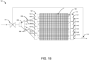
- the heat exchanger 100 can include an inlet header 102 comprising one or more hollow compartments 104-1 to 104-N (collectively designated as first compartments 104, herein) separated by one or more first walls 106-1 to 106-N (collectively referred to as first walls or first partition walls 106, herein).
- the heat exchanger can further include an outlet header 110, which may or may not include partitioned compartments.
- the heat exchanger 100 can include a heat exchange section comprising a plurality of microchannel tubes (collectively designated as MCHX tubes 108, herein) extending between and fluidically connected to at least one of the first compartments 104-1 to 104-N and the outlet header 110.
- the heat exchange section of the heat exchanger 100 can include a plurality of heat-dissipating fins (F) in thermal contact with the plurality of tubes 108 to increase the exchange/transfer area of the tubes 108 and correspondingly enhance the heat exchange.
- the heat exchanger can be associated with one or more of a heating, ventilation, air-conditioning, and cooling (HVAC) system, and a transport refrigeration unit, but is not limited to the like.
- HVAC heating, ventilation, air-conditioning, and cooling
- the inlet header 102 and the outlet header 110 may be configured in a vertical orientation, with the plurality of tubes 108 extending between the inlet header 102 and the outlet header 110.
- the inlet header 102 and the outlet header 110 may also be horizontal or some intermediate angle between vertical and horizontal.
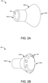
- the heat exchanger 100 can include an external fluid distributor 200 (also referred to as first distributor, herein) comprising an inlet port 202 and a plurality of outlet ports 204 (shown in FIG. 2A and 2B ), where the inlet port 202 of the first distributor 200 can be fluidically connected to an expansion valve (EV) associated with the heat exchanger 100 to receive a fluid (two-phase refrigerant).
- an external fluid distributor 200 also referred to as first distributor, herein
- EV expansion valve
- the heat exchanger assembly 100 can include a plurality of feeder pipes 206 (collectively referred to as feeder pipe 206, herein) configured between the first compartments 104 of the inlet header 102 and the outlet ports 204 of the first distributor 200, such that each of the first compartments 104 remains fluidically connected to one of the outlet ports 204 of the first distributor 200 by one of the feeder pipes 206 to allow flow of an equal volume of fluid (two-phase refrigerant supplied by the expansion valve EV) from the first distributor 200 into each of the first compartments 104.
- feeder pipe 206 collectively referred to as feeder pipe 206, herein
- the first distributor 200 can include a housing of a predefined shape that can include the inlet port 202 at a first end of the housing and the plurality of outlet ports at a second end of the housing. Further, the inlet port 202 can be in fluidic communication with the plurality of outlet ports 204 via a plurality of fluidic passages extending within the housing. In one or more embodiments, the outlet ports 204 of the first distributor 200 can be non-uniform in size such that different volume of fluid can be provided in different first compartments 104 of the inlet header 102.
- the heat exchanger 400 can include a fan 402 which may cause air flow maldistribution.
- the section 'A' of the heat exchanger 400 may receive lesser air flow compared to the section 'B' of the heat exchanger 400.
- the non-uniform size of the outlet ports 204 of the first distributor 200 may cause different volume of fluid to flow in different first compartments 104 of the inlet header 102, such that negative effects of the air flow maldistribution may be mitigated.
- the non-uniform size of the outlet ports 204 of the first distributor 200 may mitigate the negative effects of the air flow maldistribution in heat exchangers having other configurations as well.
- the first distributor 200 can have a solid conical shape that can include a substantially circular base 208-1, and a curved lateral surface 208-3 extending from a vortex end 208-2 of the first distributor 200 to the circular base 208-1.
- the conical distributor 200 can include the inlet port 202 at the vortex end 208-2, and the plurality of outlet ports 204 being configured circumferentially around the circular base 208-1 and in fluidic communication with the inlet port via a plurality of fluidic passages to form a shower-head type construction. Further, referring to FIG.
- the feeder pipes 206 can extend from the outlet ports 204 at the base 208-1 of the conical header 200 and can be further fluidically connected to the first compartments 104 of the inlet header 102 as shown in FIGs. 1A to 1C .
- the diameter and length of the feeder tube 206 can be non-uniform having predetermined diameters and predetermined lengths such that a predetermined target pressure drop is achieved in the feeder tubes 206.
- the predetermined diameters and predetermined lengths can be selected such equal pressure drop is achieved in all the feeder tubes 206 to supply equal volume of fluid through each of the feeder tubes 206.
- first distributor 200 having a conical shape or shower-head type construction
- teachings of this specification are equally applicable for the first distributor 200 having a different shape or types as far as the outlet ports of the first distributor 200 are connected to each first compartment of the inlet header via the feeder pipes to supply an equal volume of the fluid comprising of liquid-vapor mixture from the expansion valve into the first compartments, and all such embodiments are well within the scope of this invention.
- the feeder pipe 206 associated with each of the first compartment 104 can be connected to the bottom end of the corresponding first compartment 104 to prevent accumulation of the fluid or creation of standing column of the fluid within the first compartments 104 of the header 102 and further facilitate even distribution of the fluid into the tubes 108, however, the feeder pipe 206 associated with each of the first compartment 104 may also be connected to a middle end or an upper end or other position in the corresponding first compartment 104 as long as the standing column of the fluid is not created in the compartments of the inlet header 102.
- the fluid (two-phase refrigerant) supplied by the expansion valve EV can be received by the first distributor 200 at the inlet port 202 and the outlet ports 204 can further meter an equal or predetermined volume of the fluid into each of the first compartments 104 of the inlet header 102.
- the smaller volume of the first compartments 104 (compared to an inlet header of the same size and without any partition walls) can allow the fluid (received from the first distributor 200 via the feeder pipes 206) to be uniformly mixed and evenly distributed into the ports of the microchannel tubes 108 associated with the corresponding compartment 104.
- an internal flow mixer or distribution device can be present.
- the heat exchanger 100 can achieve a more uniform distribution of the fluid across all the microchannel tubes 108, thereby enhancing the overall thermal performance of the heat exchanger 100.
- the outlet header 110 can also include one or more hollow compartments 112-1 to 112-N (collectively designated as second compartments 112, herein) separated by one or more second walls 114-1 to 114-N (collectively referred to as second walls or partition walls 114, herein).
- the inlet header 102 and the outlet header 110 can be hollow members having parallelly placed walls separated by a predefined distance to create the compartments therewithin.
- the inlet header 102 and the outlet header 110 may have a cylindrical profile or a substantially curved profile with flat bases at the two opposite ends but is not limited to the like. Referring to FIG.
- the heat exchanger 100 can include a fluid collector device 116 fluidically connected to the second compartments 112 of the outlet header 110.
- the collector device 116 can be configured to receive and collect the fluid from each of the second compartments 112.
- the first compartments 104 and/or the second compartments 112 may have equal volumes or the volumes may vary.
- the heat exchange section can include a plurality of circuits 108-A to 108-N, where each circuit 108-A to 108-N can include a group of tubes 108 that can be a subset of a total number of the plurality of tubes 108 based on the volume of the corresponding compartment 104.
- the group of tubes associated with each refrigerant circuit 108-A to 108-N can include a predefined number of passes and a predefined number of turns.
- the outlet header 110 may not have any partition walls. Further, a first end of the group of tubes 108 associated with each of the circuits can be fluidically connected to one of the first compartments 104 of the inlet header 102, and a second end of the corresponding group of tubes 108 associated with each of the circuits can be fluidically connected to the outlet header 110.
- the number of the tubes 108 in a subsequent pass among the predefined number of passes can be greater than the number of the tubes 108 in a corresponding preceding pass.
- the number of tubes in the pass P1 can be greater than the number of tubes in the pass P2.
- the number of tubes in the pass P2 can be greater than the number of tubes in the pass P3.
- the number of the tubes 108 in a subsequent pass among the predefined number of passes can be less than the number of the tubes 108 in a corresponding preceding pass.
- the number of tubes 108 in the pass P1 can be less than the number of tubes 108 in the pass P2.
- the number of tubes 108 in the pass P2 can be less than the number of tubes 108 in the pass P3.
- each of the passes associated with the circuits can be fluidically connected by a flow-mixing device or an internal flow distribution device.
- An outlet end of the tubes 108 associated with a preceding pass can be connected to inlet(s) of the flow-mixing device and an inlet end of the tubes 108 associated with a subsequent pass can be connected to outlets of the flow-mixing device.
- the flow mixing device(s) can be disposed of in each of the second compartments 112 associated with the outlet header 110, however, the flow mixing device(s) can also remain outside of the outlet header 110.
- the second distributor of the inlet header 102 can include a distribution tube 118, that may or may not be partitioned, extending longitudinally through the first compartments 104-1 to 104-N over an entire length of the inlet header 102.
- the distribution tube 118 can include a plurality of cavities extending longitudinally along a length of the distribution tube 118, where the cavities can include one or more ports opening in each of the first compartments.
- the distribution tube 118 can include the plurality of cavities extending longitudinally along a length of the distribution tube 118 and configured radially around a central axis of the distribution tube, where each of the cavities can include the ports opening in each of the first compartments 104-1 to 104-N.
- the cavities of the distribution tube can be in the form of concentric rings, where the exterior of the distribution tube may have a stepped shape resulting from the termination of the ring after the ports opening in the destination compartment 104.
- the distribution tube 118 can act as an internal fluid distributor for the inlet header 102, which can receive fluid from the expansion valve (EV) and supply the fluid into each of the compartments 104 and further evenly distribute the fluid into the microchannel tubes associated with the corresponding compartment 104.
- the second distributor of the inlet header 102 can include a plurality of distribution tubes extending longitudinally through the inlet header 102, such that each of the distribution tubes extends up to and remains fluidically connected to one of the first compartments 104-1 to 104-N, thereby fluidically connecting the expansion valve (EV) to each of the first compartments 104-1 to 104-N of the inlet header 102.
- each of the distribution tubes can act as an internal fluid distributor for one of the first compartments 104 of the inlet header 102, which can receive fluid from the expansion valve (EV) and supply the fluid into the respective first compartments 104 and further evenly distribute the fluid into the microchannel tubes associated with the corresponding first compartment 104.
- each of the first compartments 104 of the inlet header 102 and the second compartments 112 of the outlet header 110 can include an orifice plate 120 having openings.
- the orifice plate 120 can be configured coaxially within the inlet header 102.
- a first end of the group of tubes 108 associated with each of the circuits can be fluidically connected to one of the first compartments 104 of the inlet header 102, and a second end of the corresponding group of tubes 108 associated with each of the circuits can be fluidically connected to one of the second compartments 112 of the outlet header 110, such that the fluid can flow between the first compartments 104 and the second compartments 112 while flowing through the orifice plates 120 and finally flowing out of the outlet header 110 into the fluid collector device 116.
- this invention overcomes the drawbacks, limitations, and shortcomings associated with existing heat exchangers and corresponding fluid distributors by providing an improved, effective, and compact solution that helps the heat exchanger supply an equal volume of the fluid into the compartments of the inlet header and further helps achieve a more uniform distribution of the fluid phases across all the microchannel tubes, thereby enhancing the overall thermal performance of the heat exchanger.
Landscapes
- Engineering & Computer Science (AREA)
- Physics & Mathematics (AREA)
- Mechanical Engineering (AREA)
- Thermal Sciences (AREA)
- General Engineering & Computer Science (AREA)
- Heat-Exchange Devices With Radiators And Conduit Assemblies (AREA)
- Details Of Heat-Exchange And Heat-Transfer (AREA)
Applications Claiming Priority (1)
| Application Number | Priority Date | Filing Date | Title |
|---|---|---|---|
| US202363593324P | 2023-10-26 | 2023-10-26 |
Publications (1)
| Publication Number | Publication Date |
|---|---|
| EP4545899A1 true EP4545899A1 (de) | 2025-04-30 |
Family
ID=93061706
Family Applications (1)
| Application Number | Title | Priority Date | Filing Date |
|---|---|---|---|
| EP24205603.4A Pending EP4545899A1 (de) | 2023-10-26 | 2024-10-09 | Mikrokanalwärmetauscher |
Country Status (3)
| Country | Link |
|---|---|
| US (1) | US20250137738A1 (de) |
| EP (1) | EP4545899A1 (de) |
| CN (1) | CN119901168A (de) |
Citations (4)
| Publication number | Priority date | Publication date | Assignee | Title |
|---|---|---|---|---|
| US20060201197A1 (en) * | 2005-03-09 | 2006-09-14 | Lg Electronics Inc. | Refrigerant distributing device for multi-type air conditioner |
| WO2013005729A1 (ja) * | 2011-07-05 | 2013-01-10 | シャープ株式会社 | 熱交換器及びそれを搭載した空気調和機 |
| US20150101363A1 (en) * | 2012-04-26 | 2015-04-16 | Mitsubishi Electric Corporation | Refrigerant distributing device and heat exchanger including the same |
| JP2015203506A (ja) * | 2014-04-11 | 2015-11-16 | パナソニックIpマネジメント株式会社 | 熱交換器 |
-
2024
- 2024-10-09 EP EP24205603.4A patent/EP4545899A1/de active Pending
- 2024-10-16 US US18/916,817 patent/US20250137738A1/en active Pending
- 2024-10-18 CN CN202411457985.0A patent/CN119901168A/zh active Pending
Patent Citations (4)
| Publication number | Priority date | Publication date | Assignee | Title |
|---|---|---|---|---|
| US20060201197A1 (en) * | 2005-03-09 | 2006-09-14 | Lg Electronics Inc. | Refrigerant distributing device for multi-type air conditioner |
| WO2013005729A1 (ja) * | 2011-07-05 | 2013-01-10 | シャープ株式会社 | 熱交換器及びそれを搭載した空気調和機 |
| US20150101363A1 (en) * | 2012-04-26 | 2015-04-16 | Mitsubishi Electric Corporation | Refrigerant distributing device and heat exchanger including the same |
| JP2015203506A (ja) * | 2014-04-11 | 2015-11-16 | パナソニックIpマネジメント株式会社 | 熱交換器 |
Also Published As
| Publication number | Publication date |
|---|---|
| CN119901168A (zh) | 2025-04-29 |
| US20250137738A1 (en) | 2025-05-01 |
Similar Documents
| Publication | Publication Date | Title |
|---|---|---|
| EP2082181B1 (de) | Parallelstromwärmetauscher | |
| EP2278246B1 (de) | Verteilerrohr mit gleichmäßiger Kühlflüssigkeitsverteilung | |
| KR100908769B1 (ko) | 병류 열교환기와, 균일한 냉매 유동을 촉진하는 방법 | |
| EP2853843B1 (de) | Kältemittelverteiler und wärmetauscher mit dem kältemittelverteiler | |
| US20080190134A1 (en) | Refrigerant flow distributor | |
| CN101520282B (zh) | 微通道换热器及换热系统 | |
| EP3779346B1 (de) | Verteiler und wärmetauscher | |
| EP3120097B1 (de) | Verdampfer für mikrokanal-wärmetauscher | |
| GB2250336A (en) | Heat exchanger | |
| WO2009139998A2 (en) | Microchannel heat exchanger with enhanced refrigerant distribution | |
| US10161685B2 (en) | Heat exchanger with partitioned inlet header for enhanced flow distribution and refrigeration system using the heat exchanger | |
| EP4246075A2 (de) | Wärmetauscher für wärmepumpenanwendungen | |
| US20250137738A1 (en) | Microchannel heat exchanger | |
| EP4589238A1 (de) | Fluidverteiler für einen wärmetauscher | |
| US20250283673A1 (en) | Laminated header for a microchannel heat exchanger | |
| EP4517247A1 (de) | Flüssigkeitsverteiler für mikrokanalwärmetauscher | |
| WO2021214849A1 (ja) | 空気調和機、冷凍機及び分配器 | |
| HK1138637B (en) | Minichannel heat exchanger header insert for distribution | |
| HK1117223B (en) | Tube inset and bi-flow arrangement for a header of a heat pump | |
| HK1138362A1 (en) | Multi-pass heat exchangers having return manifolds with distributing inserts | |
| HK1138362B (en) | Multi-pass heat exchangers having return manifolds with distributing inserts |
Legal Events
| Date | Code | Title | Description |
|---|---|---|---|
| PUAI | Public reference made under article 153(3) epc to a published international application that has entered the european phase |
Free format text: ORIGINAL CODE: 0009012 |
|
| STAA | Information on the status of an ep patent application or granted ep patent |
Free format text: STATUS: THE APPLICATION HAS BEEN PUBLISHED |
|
| AK | Designated contracting states |
Kind code of ref document: A1 Designated state(s): AL AT BE BG CH CY CZ DE DK EE ES FI FR GB GR HR HU IE IS IT LI LT LU LV MC ME MK MT NL NO PL PT RO RS SE SI SK SM TR |
|
| STAA | Information on the status of an ep patent application or granted ep patent |
Free format text: STATUS: REQUEST FOR EXAMINATION WAS MADE |
|
| 17P | Request for examination filed |
Effective date: 20251027 |
|
| GRAP | Despatch of communication of intention to grant a patent |
Free format text: ORIGINAL CODE: EPIDOSNIGR1 |
|
| STAA | Information on the status of an ep patent application or granted ep patent |
Free format text: STATUS: GRANT OF PATENT IS INTENDED |
|
| RIC1 | Information provided on ipc code assigned before grant |
Ipc: F28F 9/02 20060101AFI20260305BHEP Ipc: F28D 1/053 20060101ALI20260305BHEP |
|
| INTG | Intention to grant announced |
Effective date: 20260320 |