EP4545930A1 - Dispositif et procédé de numérisation pour échantillon liquide - Google Patents
Dispositif et procédé de numérisation pour échantillon liquide Download PDFInfo
- Publication number
- EP4545930A1 EP4545930A1 EP23829412.8A EP23829412A EP4545930A1 EP 4545930 A1 EP4545930 A1 EP 4545930A1 EP 23829412 A EP23829412 A EP 23829412A EP 4545930 A1 EP4545930 A1 EP 4545930A1
- Authority
- EP
- European Patent Office
- Prior art keywords
- digitizing
- liquid sample
- channel
- temperature
- heating assembly
- Prior art date
- Legal status (The legal status is an assumption and is not a legal conclusion. Google has not performed a legal analysis and makes no representation as to the accuracy of the status listed.)
- Pending
Links
Images


Classifications
-
- G—PHYSICS
- G01—MEASURING; TESTING
- G01N—INVESTIGATING OR ANALYSING MATERIALS BY DETERMINING THEIR CHEMICAL OR PHYSICAL PROPERTIES
- G01N1/00—Sampling; Preparing specimens for investigation
- G01N1/28—Preparing specimens for investigation including physical details of (bio-)chemical methods covered elsewhere, e.g. G01N33/50, C12Q
-
- G—PHYSICS
- G01—MEASURING; TESTING
- G01N—INVESTIGATING OR ANALYSING MATERIALS BY DETERMINING THEIR CHEMICAL OR PHYSICAL PROPERTIES
- G01N1/00—Sampling; Preparing specimens for investigation
- G01N1/28—Preparing specimens for investigation including physical details of (bio-)chemical methods covered elsewhere, e.g. G01N33/50, C12Q
- G01N1/44—Sample treatment involving radiation, e.g. heat
-
- B—PERFORMING OPERATIONS; TRANSPORTING
- B01—PHYSICAL OR CHEMICAL PROCESSES OR APPARATUS IN GENERAL
- B01L—CHEMICAL OR PHYSICAL LABORATORY APPARATUS FOR GENERAL USE
- B01L3/00—Containers or dishes for laboratory use, e.g. laboratory glassware; Droppers
- B01L3/50—Containers for the purpose of retaining a material to be analysed, e.g. test tubes
- B01L3/502—Containers for the purpose of retaining a material to be analysed, e.g. test tubes with fluid transport, e.g. in multi-compartment structures
- B01L3/5027—Containers for the purpose of retaining a material to be analysed, e.g. test tubes with fluid transport, e.g. in multi-compartment structures by integrated microfluidic structures, i.e. dimensions of channels and chambers are such that surface tension forces are important, e.g. lab-on-a-chip
- B01L3/502769—Containers for the purpose of retaining a material to be analysed, e.g. test tubes with fluid transport, e.g. in multi-compartment structures by integrated microfluidic structures, i.e. dimensions of channels and chambers are such that surface tension forces are important, e.g. lab-on-a-chip characterised by multiphase flow arrangements
- B01L3/502784—Containers for the purpose of retaining a material to be analysed, e.g. test tubes with fluid transport, e.g. in multi-compartment structures by integrated microfluidic structures, i.e. dimensions of channels and chambers are such that surface tension forces are important, e.g. lab-on-a-chip characterised by multiphase flow arrangements specially adapted for droplet or plug flow, e.g. digital microfluidics
-
- B—PERFORMING OPERATIONS; TRANSPORTING
- B01—PHYSICAL OR CHEMICAL PROCESSES OR APPARATUS IN GENERAL
- B01L—CHEMICAL OR PHYSICAL LABORATORY APPARATUS FOR GENERAL USE
- B01L7/00—Heating or cooling apparatus; Heat insulating devices
-
- B—PERFORMING OPERATIONS; TRANSPORTING
- B01—PHYSICAL OR CHEMICAL PROCESSES OR APPARATUS IN GENERAL
- B01L—CHEMICAL OR PHYSICAL LABORATORY APPARATUS FOR GENERAL USE
- B01L2200/00—Solutions for specific problems relating to chemical or physical laboratory apparatus
- B01L2200/06—Fluid handling related problems
- B01L2200/0673—Handling of plugs of fluid surrounded by immiscible fluid
-
- B—PERFORMING OPERATIONS; TRANSPORTING
- B01—PHYSICAL OR CHEMICAL PROCESSES OR APPARATUS IN GENERAL
- B01L—CHEMICAL OR PHYSICAL LABORATORY APPARATUS FOR GENERAL USE
- B01L2300/00—Additional constructional details
- B01L2300/08—Geometry, shape and general structure
- B01L2300/0809—Geometry, shape and general structure rectangular shaped
- B01L2300/0816—Cards, e.g. flat sample carriers usually with flow in two horizontal directions
-
- B—PERFORMING OPERATIONS; TRANSPORTING
- B01—PHYSICAL OR CHEMICAL PROCESSES OR APPARATUS IN GENERAL
- B01L—CHEMICAL OR PHYSICAL LABORATORY APPARATUS FOR GENERAL USE
- B01L2300/00—Additional constructional details
- B01L2300/08—Geometry, shape and general structure
- B01L2300/0832—Geometry, shape and general structure cylindrical, tube shaped
- B01L2300/0838—Capillaries
-
- B—PERFORMING OPERATIONS; TRANSPORTING
- B01—PHYSICAL OR CHEMICAL PROCESSES OR APPARATUS IN GENERAL
- B01L—CHEMICAL OR PHYSICAL LABORATORY APPARATUS FOR GENERAL USE
- B01L2300/00—Additional constructional details
- B01L2300/18—Means for temperature control
- B01L2300/1805—Conductive heating, heat from thermostatted solids is conducted to receptacles, e.g. heating plates, blocks
- B01L2300/1827—Conductive heating, heat from thermostatted solids is conducted to receptacles, e.g. heating plates, blocks using resistive heater
-
- B—PERFORMING OPERATIONS; TRANSPORTING
- B01—PHYSICAL OR CHEMICAL PROCESSES OR APPARATUS IN GENERAL
- B01L—CHEMICAL OR PHYSICAL LABORATORY APPARATUS FOR GENERAL USE
- B01L2300/00—Additional constructional details
- B01L2300/18—Means for temperature control
- B01L2300/1838—Means for temperature control using fluid heat transfer medium
- B01L2300/1844—Means for temperature control using fluid heat transfer medium using fans
-
- B—PERFORMING OPERATIONS; TRANSPORTING
- B01—PHYSICAL OR CHEMICAL PROCESSES OR APPARATUS IN GENERAL
- B01L—CHEMICAL OR PHYSICAL LABORATORY APPARATUS FOR GENERAL USE
- B01L2300/00—Additional constructional details
- B01L2300/18—Means for temperature control
- B01L2300/1838—Means for temperature control using fluid heat transfer medium
- B01L2300/185—Means for temperature control using fluid heat transfer medium using a liquid as fluid
-
- B—PERFORMING OPERATIONS; TRANSPORTING
- B01—PHYSICAL OR CHEMICAL PROCESSES OR APPARATUS IN GENERAL
- B01L—CHEMICAL OR PHYSICAL LABORATORY APPARATUS FOR GENERAL USE
- B01L2300/00—Additional constructional details
- B01L2300/18—Means for temperature control
- B01L2300/1861—Means for temperature control using radiation
-
- B—PERFORMING OPERATIONS; TRANSPORTING
- B01—PHYSICAL OR CHEMICAL PROCESSES OR APPARATUS IN GENERAL
- B01L—CHEMICAL OR PHYSICAL LABORATORY APPARATUS FOR GENERAL USE
- B01L2300/00—Additional constructional details
- B01L2300/18—Means for temperature control
- B01L2300/1894—Cooling means; Cryo cooling
Definitions
- the present application relates to the technical field of sample and reagent handling, and in particular to a device and a method for digitizing a liquid sample.
- Digitization of liquids is the distribution and analysis of liquids and entities (e.g., particles, microorganisms, cells, molecules and the like) therein.
- entities e.g., particles, microorganisms, cells, molecules and the like
- spatial distributing techniques which are used to distribute entities in a solution or suspension into different subunits.
- the main digitizing techniques commonly used in digitization of liquid are microcavity technology and micro-droplet technology.
- microcavity technology is based on an integrated fluidic pathway chip and relies on microstructures on the chip to divide the liquid into separate tiny droplet units.
- microcavity technology is used for digitizing operation, the operation is time-consuming, the reaction cost is high, and the structure of the equipment used to realize the digitizing operation is complicated.
- Micro-droplet technology is based on the principle of water-in-oil, and it utilizes shear force to disperse the liquid into the immiscible oil phase, thereby forming water-in-oil micro-droplets.
- the use of micro-droplet technology for digitizing operations requires the use of a great deal of oil phases and surfactants, which is costly.
- the present application provides a device and a method for digitizing a liquid sample, which are used to remove the defects of complicated digitizing operation, time-consuming, and high reaction cost in the prior art, and to realize digitization of a liquid sample with simple operation, low cost, and short time.
- the present application provides a device for digitizing a liquid sample, the device comprises:
- the digitizing channel comprises, in an extended direction, at least one low-temperature zone and at least one high-temperature zone, the heating assembly is provided in each of the high-temperature zones, and the high-temperature zones are arranged alternately with the low-temperature zones.
- each of the low-temperature zone is provided with a cooling assembly.
- the container comprises a microchannel chip, and a microchannel of the microchannel chip forms the digitizing channel.
- the heating assembly is a laser source or a thermal light source, and the heating assembly is located on the side of the microchannel chip where the microchannel is provided.
- the device further comprises:
- the cooling assembly is a water cooling box or a cooling substrate.
- the container comprises a microchannel tube, and the pathway of the microchannel tube forms the digitizing channel; and the heating assembly is an electric heater plate, and the electric heater plate being provided in a high temperature zone of the digitizing channel.
- the container comprises a capillary coil, and the pathway of the capillary coil forms the digitizing channel;
- the heating assembly is an electric heater bracket, the capillary coil is mounted on the electric heater bracket, and contact position of the electric heater bracket with the capillary coil is the high temperature zone of the digitizing channel.
- the present application also provides a method of digitizing a liquid sample, based on the device for digitizing a liquid sample described above, the method comprises:
- the present application provides a device and a method for digitizing a liquid sample.
- digitization of a liquid sample to be digitized can be realized by filling the liquid sample to be digitized into a digitizing channel of a preset size, and then heating the digitizing channel at a temperature exceeding the cloud point of the liquid sample.
- the present application allows digitization to be carried out directly in a container, the overall operation is simple, and the container, the heating assembly and the like used in the present application belong to conventional instruments with relatively low price, and the digitizing operation of the liquid sample to be digitized can be realized in a relatively short period of time.
- micellar phase micro-droplets 11: micellar phase micro-droplets ; 12: aqueous phase; 21: aqueous phase; 22: micellar phase; 31: small-size container; 32: aqueous phase micro-droplets; 33: micellar phase micro-droplets; 41: fan; 42: aqueous phase; 43: micellar phase; 44: microchannel tube; 45: electric heater plate; 51: light source; 52: schematic light rays; 53: mask; 54: mask slot hole; 55: microchannel chip; 56: cooling system; 61: mask with transparent effect; 62: microchannel; 71: schematic light rays; 72: micellar phase; 73: transparentized schematic mask; 74: aqueous phase; 81: capillary coil; 82: heater bracket; 83: fan; 84: fan cooling airflow; 91: micellar phase; 92: aqueous phase; 101: laser source; 102: Galvo scanning lens; 103: laser beam; 104: microchannel chip
- a device for digitizing a liquid sample of the present application is described below in combination with Figures 1-10 .
- Nonionic surfactants are surfactants whose molecules contain ether groups that do not dissociate in aqueous solution as the main hydrophilic group, and whose surface activity is embodied by neutral molecules.
- Nonionic surfactants have high surface activity, good properties of solubilization, washing, static electricity resistance, calcium soap dispersion and other properties, low irritation, as well as excellent wetting and washing function. It can be applied in a wider pH range than general ionic surfactants, and can also be used together with other ionic surfactants. Adding a small amount of nonionic surfactant to ionic surfactants can increase the surface activity of the system.
- Nonionic surfactants can be classified into polyoxyethylene type, polyol type, alkanol amide type, polyether type, oxidized amine type and so on according to the structure of hydrophilic group.
- a clear homogeneous nonionic surfactant solution (the nonionic surfactant can be of polyoxyethylene type, polyol type, polyether type, oxidized amine type and the like, or mixtures containing these surfactants) will spontaneously form two mutually incompatible phases, a micellar phase and an aqueous phase with a lower concentration of the surfactant, due to the reduction of the solubility caused by the change of temperature or other conditions, and the temperature threshold at which the phase separation starts to occur is called the cloud point, and the phase separation process is a reversible physical change. It is generally believed that this phenomenon is caused by the growth and structural change of micelles, micelles connecting into a network, and the action of H-bonds between water molecules and micelles.
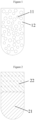
- micellar phase micro-droplets 11 and aqueous phase 12 are formed first, which is manifested superficially by the occurrence of turbidity in the solution.
- the micelle phase micro-droplets 11 gradually aggregate, eventually form two separate clear macroscopic phases - aqueous phase 21 and micelle phase 22.
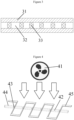
- the present application transfers the digitization process to a small-size container 31, the small-size container may be a capillary, or a microchannel, with at least one dimension of ⁇ 1 mm in its dimensions.
- the formed aqueous phase micro-droplets 32 and micellar phase micro-droplets 33 are difficult to aggregate due to obstruction of the diffusion in this small-size container, and multiple separate micellar phase zones and aqueous phase zones will be formed in the small-size container, thereby achieving uniform separation of the aqueous phase, also known as the digitization process.
- This digitization method is short in time, cost-effective, simple, and significantly better than the two current methods for digitizing aqueous solutions.
- the micellar and aqueous phases are reversibly converted back to a single phase, which facilitates other subsequent operations.
- different temperature gradients can also be applied to the small-size container so that the micellar phase is generated only in the zone where the temperature is higher than the cloud point, which allows for better control of the digitization process.
- the high temperature portion of the temperature gradient can be realized by means of resistance heating selected zones, as shown in Figure 4 , or light heating selected zones, as shown in Figure 5 ; and the low temperature portion of the temperature gradient may be realized by means of air-cooling, water-cooling, or diode-cooling.
- Examples of the present application provide a device for digitizing a liquid sample, comprising: a container and a heating assembly.
- the container is provided with at least one digitizing channel for accommodating the liquid sample, and the digitizing channel has a size less than or equal to a preset value to limit the diffusion of the digitized liquid sample within the digitizing channel.
- the heating assembly at least partially heats the digitizing channel, and a heating temperature of the heating assembly is not lower than a cloud point temperature of the liquid sample.
- the preset value may be in the range of greater than or equal to 1 micrometer and less than or equal to 1 millimeter.
- the present application can realize the digitization of the liquid sample to be digitized by filling the liquid sample to be digitized into the digitizing channel of a preset size, and then heating the digitizing channel at a temperature exceeding the cloud point of the liquid sample.
- the present invention allows digitization to be carried out directly in a container, the overall operation is simple, and the container and heating assembly used belong to relatively low-priced conventional instruments, and the present invention can realize the digitizing operation of the liquid sample to be digitized in a relatively short period of time.
- the liquid sample is a colloidal solution exceeding a critical micelle concentration (CMC), which is defined as one of the most important physical quantities characterizing the structure and performance of the surfactant, and according to the size of the CMC value of the surfactant, it is possible to design the amount of the surfactant to be added in order to obtain a solution with controllable micelle size and shape.
- CMC critical micelle concentration
- the lowest concentration of surfactant required for the formation of micelles is called the critical micelle concentration.
- Cloud point is a characteristic constant of nonionic surfactants, which is influenced by the molecular structure of surfactants and coexisting substances.
- a turbid phenomenon will appear, surfactant transforms from completely dissolved state to partially dissolved state, the temperature when the transformation occurs is the cloud point temperature.
- the cloud point is the temperature at which phase separation occurs in a homogeneous micellar solution of a nonionic surfactant.
- the cooling component is a water-cooling box, a cooling substrate, a fan, or other device that have a cooling effect
- the cooling substrate is a semiconductor cooler
- the container further comprises a microchannel tube, and the channel of the microchannel tube forms the digitizing channel, enabling the solution sample to fill the channel of the microchannel tube.
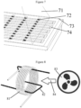
- the heating assembly is an electric heater plate 45
- the liquid sample is filled in the microchannel tube 44
- the channel of the microchannel tube 44 forms a digitizing channel
- the electric heater plate 45 is arranged in the high temperature zone of the digitizing channel
- the part where the electric heater plate 45 is in contact with the microchannel tube 44 is the high temperature zone of the microchannel tube 44
- the electric heater plate 45 heats up the liquid sample located in the microchannel tube 44 to increase the temperature to the cloud point temperature, thereby separating into aqueous phase 42 and micellar phase 43.
- a fan 41 is also configured to air-cool the low-temperature zone of the microchannel tube by rotating the air supply.
- the container in the present application includes a microchannel chip, and the microchannel of the microchannel chip form a digitizing channel.
- the heating assembly is a laser source or a thermal light source, and the heating assembly is located on the side of the microchannel chip where a microchannel is provided, to heat the high temperature zone of the digitizing channel.
- the device for digitizing a liquid sample further comprises: a light-shielding plate, which is disposed on the side of the microchannel chip where a digitizing channel is provided, and disposed between the microchannel chip and the heating assembly.
- the light-shielding plate is provided with a light-transmitting slot, and the light-transmitting slot is provided in correspondence with the digitizing channel, so that light from a thermal light source is irradiated through the light-transmitting slot to the high temperature zone of the digitizing channel.
- the microchannel chip includes a plurality of microchannels, and the diameter of the microchannels is not larger than one millimeter, which can achieve the technical effect of preventing diffusion of the digitized liquid sample in the digitizing channel.
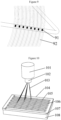
- the heating assembly in this Example is a thermal light source 51, as shown by the schematic light rays 52 in the figure.
- the container comprises a microchannel chip 55, and the microchannel 62 of the microchannel chip 55 form a digitizing channel.
- the thermal light source 51 is located on the side of the microchannel chip 55 where the microchannel 62 is provided.
- the light-shielding plate is a mask 53, the mask 53 is disposed on the side of the microchannel chip 55 where the digitized channel is provided, and disposed between the microchannel chip 55 and the thermal light source 51.
- the mask 53 is provided with a mask slot hole 54, and the mask slot hole 54 is provided in correspondence with the digitizing channel.
- the present application also provides a method for digitizing a liquid sample, the method comprises the following steps:
- the liquid sample is a colloidal solution exceeding a critical micelle concentration
- the heating assembly is heated at a temperature not lower than the cloud point temperature of the liquid sample.
- the present invention proposes a new method for digitizing liquids, namely a new method for digitizing liquid samples, by utilizing the phenomenon that a colloidal solution exceeding a critical micelle concentration generates turbidity when it is heated above the cloud point, and heating the colloidal solution in a small-size channel, which causes the colloidal solution to spontaneously separate into two phases, and due to the obstruction of diffusion in the small-size tube, the separated two phases will appear alternately, thus separating the aqueous phase into homogeneous micro-droplets to achieve digitization of the aqueous solution.
- the specific operation of digitizing a liquid sample using the device for digitizing a liquid sample as shown in Figures 5, 6 , and 7 includes: 1 g of Triton X-114 was vortexed and mixed with 5 ml of cool water sufficiently, the resultant was centrifuged on a centrifuge at 3000 G for 5 minutes, and then the resulted mixed solution was filled into a microchannel chip 55.
- the microchannel chip 55 was placed on a diode-cooled copper thermally-conductive substrate with the substrate temperature being controlled at 5-10 °C.
- microchannel chip 55 there was a slotted tin foil mask 53 covering the microchannel chip 55, and the chip mask 53 was irradiated using a high power thermal light source 51 with visible to infrared wavelength band from the above of the microchannel chip 55, and part of the light is irradiated through the mask slot holes 54 to the microchannel zone of the chip and causes the temperature of the solution in the microchannel to increase, and when the temperature of irradiated zones of the channel reaches 22°C, the micellar phases 72 were formed in these zones of the channel, and the channel was separated into a plurality of separated sections with alternating aqueous phase 74 and micellar phase 72.
- the container further comprises a capillary coil, the channel of the capillary coil forms a digitizing channel, and the liquid sample is filled into the channel formed by the capillary coil.
- the heating assembly is an electric heating bracket
- the capillary coil is mounted on the electric heating bracket
- the contact position of the electric heating bracket with the capillary coil is a high temperature zone of the digitizing channel
- the temperature of the heating bracket is controlled so as to make the temperature of the high temperature zone reach the cloud point temperature.
- the heating assembly is a heating bracket 82, and the heating bracket 82 begins to heat when it is energized.
- the container includes a capillary coil 81, and the channel of the capillary coil 81 forms a digitizing channel.
- the capillary coil 81 is mounted on the electric heating bracket 82, and the contact position between the electric heating bracket 82 and the capillary coil 81 is a high temperature zone of the digitizing channel.
- the cooling component is a fan 83, as shown in Figure 8 , it is a fan cooling airflow 84, and the fan cooling airflow 84 is blown toward the capillary coil 81, cooperating with the heating bracket 82 to form a temperature gradient of a high-temperature zone and a low-temperature zone in the digitizing channel.
- the heating bracket 82 is energized to heat different positions of the digitizing channel of the capillary coil 81, and after the temperature at the different positions rises to the cloud point temperature of the liquid sample, the liquid sample begins to undergo digitization and is separated into a micellar phase 91 and a water phase 92.
- the specific operation of digitizing a liquid sample using the device for digitizing a liquid sample as shown in Figures 8 and 9 includes: 1 g of polysorbate 80 was vortexed and mixed with 5 ml of water sufficiently, the resultant was centrifuged on a centrifuge at 3000 G for 5 minutes, and then the resulted mixed solution was filled into a quartz capillary coil 81.
- the quartz capillary coil was supported by a heater bracket 82, and a fan 83 may cool the entire quartz capillary coil.
- the heater bracket 82 was energized, the bracket generated heat to heat the quartz capillary coil in contact with the bracket, and then the fan 83 blew air onto the whole quartz capillary coil 81 to keep the temperature of the whole coil constant.
- the heating power of the bracket and the air volume of fan were controlled, so that the temperatures of the quartz capillary coil and direct contact positions increased, while the temperature of the other positions of the coil kept constant.
- the micellar phase 91 was generated at the positions of the quartz capillary tube where the temperature was raised.
- a plurality of separated sections with alternating micellar phase and water phase were regularly generated throughout the whole quartz capillary channel.
- the heating assembly is a laser source 101, on which a Galvo scanning lens 102 is provided, and a laser beam 103 for heating is emitted from the laser source 101.
- the container comprises a microchannel chip 107, and the microchannel of the microchannel chip 107 forms a digitizing channel.
- the laser source 101 is located on the side of the microchannel chip 107 where the microchannel is provided.
- the microchannel chip 107 is covered with a microchannel chip quartz cover 104, and the microchannel chip 107 is provided in a thermostatic water cooling box 108.
- the laser source 101 is modulated such that the laser beam 103 emitted from the Galvo scanning lens is irradiated at different positions of the microchannel of the microchannel chip 107, and the different positions are heated up due to being irradiated by the laser beam 103, and constitute high temperature portions of the digitizing channel, and when the temperature rises to the cloud point temperature of the liquid sample, the liquid sample begins to undergo digitization and is separate into a micellar phase 105 and a water phase 106.
- the specific operation of digitizing a liquid sample using the device for digitizing a liquid sample as shown in Figure 10 includes: 1 g of hydrogenated castor oil polyoxyethylene ether EL-30 was vortexed and mixed with 5 ml of water sufficiently, the resultant was centrifuged on a centrifuge at 3000 G for 5 minutes, and then the resulted mixed solution was filled into a microchannel chip 107. Above the microchannel chip, there was a quartz cover plate. The microchannel chip was placed on a circulating water-cooled thermostatic substrate of 25°C or a thermostatic water-cooled box 108.
- the microchannel chip there was a laser system configured with a Galvo scanning lens 102 to irradiate any point, line, or surface on the chip and produce thermal effect.
- the laser power was adjusted to irradiate a specific location on the microchannel on the chip, the laser beam 103 irradiated the microchannel chip quartz cover 104 so that the cover plate is heated, the use of different quartz cover plates or the use of the lasers of different wavelengths allows for direct heating of the solution in the channel through the cover plate, and when the temperatures of the solution in the irradiated zones of the channel reaches 95 °C, the micellar phase was formed in these zones of the channel, and the channel was separated into a plurality of separated sections with alternating water phase and micellar phase.
- the present application proposes a new method for digitizing liquids, namely a new method for digitizing liquid samples, by utilizing the phenomenon that a colloidal solution exceeding a critical micelle concentration generates turbidity when it is heated above the cloud point, and heating the colloidal solution in a small-size channel, which causes the colloidal solution to spontaneously separate into two phases, which appear alternately due to the obstruction of the diffusion in the small-size channel, thus separating the aqueous phase into homogeneous micro-droplets to achieve digitization of the aqueous solution.
Landscapes
- Chemical & Material Sciences (AREA)
- Health & Medical Sciences (AREA)
- Analytical Chemistry (AREA)
- General Health & Medical Sciences (AREA)
- Immunology (AREA)
- Physics & Mathematics (AREA)
- Life Sciences & Earth Sciences (AREA)
- Biochemistry (AREA)
- General Physics & Mathematics (AREA)
- Pathology (AREA)
- Dispersion Chemistry (AREA)
- Chemical Kinetics & Catalysis (AREA)
- Clinical Laboratory Science (AREA)
- Hematology (AREA)
- Sampling And Sample Adjustment (AREA)
- Automatic Analysis And Handling Materials Therefor (AREA)
Applications Claiming Priority (2)
| Application Number | Priority Date | Filing Date | Title |
|---|---|---|---|
| CN202210741871.3A CN115200953B (zh) | 2022-06-27 | 2022-06-27 | 一种液体样本的数字化装置及方法 |
| PCT/CN2023/076658 WO2024001219A1 (fr) | 2022-06-27 | 2023-02-17 | Dispositif et procédé de numérisation pour échantillon liquide |
Publications (2)
| Publication Number | Publication Date |
|---|---|
| EP4545930A1 true EP4545930A1 (fr) | 2025-04-30 |
| EP4545930A4 EP4545930A4 (fr) | 2025-11-05 |
Family
ID=83577252
Family Applications (1)
| Application Number | Title | Priority Date | Filing Date |
|---|---|---|---|
| EP23829412.8A Pending EP4545930A4 (fr) | 2022-06-27 | 2023-02-17 | Dispositif et procédé de numérisation pour échantillon liquide |
Country Status (4)
| Country | Link |
|---|---|
| US (1) | US20250383272A1 (fr) |
| EP (1) | EP4545930A4 (fr) |
| CN (1) | CN115200953B (fr) |
| WO (1) | WO2024001219A1 (fr) |
Families Citing this family (1)
| Publication number | Priority date | Publication date | Assignee | Title |
|---|---|---|---|---|
| CN115200953B (zh) * | 2022-06-27 | 2026-04-10 | 北京本立科技有限公司 | 一种液体样本的数字化装置及方法 |
Family Cites Families (14)
| Publication number | Priority date | Publication date | Assignee | Title |
|---|---|---|---|---|
| DE69429038T2 (de) * | 1993-07-28 | 2002-03-21 | Pe Corporation (Ny), Norwalk | Vorrichtung und Verfahren zur Nukleinsäurevervielfältigung |
| US20080153169A1 (en) * | 2004-07-14 | 2008-06-26 | Kazuya Hirata | Microchannel Chip Reaction Control System, Micro Total Reaction System Including the Control System, and Micro Total Analysis System |
| US9114399B2 (en) * | 2010-08-31 | 2015-08-25 | Canon U.S. Life Sciences, Inc. | System and method for serial processing of multiple nucleic acid assays |
| WO2013037284A1 (fr) * | 2011-09-15 | 2013-03-21 | The Chinese University Of Hong Kong | Plaque microfluidique et son procédé de régulation |
| US20140255270A1 (en) * | 2013-02-28 | 2014-09-11 | California Institute Of Technology | Removing sacrificial layer to form liquid containment structure and methods of use thereof |
| EP3178919B1 (fr) * | 2014-08-08 | 2021-01-06 | Panasonic Intellectual Property Management Co., Ltd. | Dispositif d'amplification d'acides nucléiques |
| CN104815710B (zh) * | 2015-04-10 | 2017-03-15 | 重庆医科大学附属永川医院 | 微流控芯片及其微通道内温度梯度场的建立方法和应用 |
| US10406528B1 (en) * | 2016-08-04 | 2019-09-10 | National Technology & Engineering Solutions Of Sandia, Llc | Non-contact temperature control system for microfluidic devices |
| CN109337963B (zh) * | 2018-10-24 | 2022-04-19 | 四川大学华西医院 | 一种连续体积梯度毛细管数字pcr方法和试剂盒 |
| CN109355178B (zh) * | 2018-10-24 | 2022-04-26 | 四川大学华西医院 | 一种连续体积梯度毛细管数字pcr装置及其使用方法 |
| CN109596838A (zh) * | 2018-12-17 | 2019-04-09 | 中国科学院电子学研究所 | 一种单细胞内多种蛋白同时定量检测系统及方法 |
| CN113652342B (zh) * | 2021-07-21 | 2024-08-23 | 广东省科学院健康医学研究所 | 一种数字pcr装置、制备方法、设备及介质 |
| CN113862140B (zh) * | 2021-09-27 | 2024-04-09 | 广东省科学院健康医学研究所 | 一种便携式液滴数字pcr装置 |
| CN115200953B (zh) * | 2022-06-27 | 2026-04-10 | 北京本立科技有限公司 | 一种液体样本的数字化装置及方法 |
-
2022
- 2022-06-27 CN CN202210741871.3A patent/CN115200953B/zh active Active
-
2023
- 2023-02-17 EP EP23829412.8A patent/EP4545930A4/fr active Pending
- 2023-02-17 WO PCT/CN2023/076658 patent/WO2024001219A1/fr not_active Ceased
- 2023-02-17 US US18/878,208 patent/US20250383272A1/en active Pending
Also Published As
| Publication number | Publication date |
|---|---|
| CN115200953A (zh) | 2022-10-18 |
| WO2024001219A1 (fr) | 2024-01-04 |
| EP4545930A4 (fr) | 2025-11-05 |
| CN115200953B (zh) | 2026-04-10 |
| US20250383272A1 (en) | 2025-12-18 |
Similar Documents
| Publication | Publication Date | Title |
|---|---|---|
| EP4545930A1 (fr) | Dispositif et procédé de numérisation pour échantillon liquide | |
| Sainis et al. | Electrostatic interactions of colloidal particles in nonpolar solvents: Role of surface chemistry and charge control agents | |
| Namura et al. | Direction control of quasi-stokeslet induced by thermoplasmonic heating of a water vapor microbubble | |
| Liu et al. | Droplet-based synthetic method using microflow focusing and droplet fusion | |
| US9198645B2 (en) | Controlled vesicle self-assembly in continuous two phase flow microfluidic channels | |
| WO2008094526A2 (fr) | Commande assistée par plasmon d'optofluidique | |
| Hu et al. | Aqueous droplet manipulation by optically induced Marangoni circulation | |
| Davanlou et al. | Thermally induced collision of droplets in an immiscible outer fluid | |
| Miao et al. | Localized surface plasmon assisted microfluidic mixing | |
| Li et al. | Gold nanorod-facilitated localized heating of droplets in microfluidic chips | |
| Bell et al. | Direct growth of CdSe semiconductor quantum dots in glass matrix by femtosecond laser beam | |
| Tamaki et al. | Microchannel-assisted thermal-lens spectrometry for microchip analysis | |
| Jonáš et al. | Thermal tuning of spectral emission from optically trapped liquid-crystal droplet resonators | |
| Dongre et al. | Fluorescence monitoring of microchip capillary electrophoresis separation with monolithically integrated waveguides | |
| CN111307714B (zh) | 基于光流控热毛细微流涡旋的液滴操控芯片及其操控方法 | |
| Ichikawa et al. | Extension of a DNA molecule by local heating with a laser | |
| US5318614A (en) | Method of burying optical waveguide paths | |
| US6103081A (en) | Heat sink for capillary electrophoresis | |
| Winterton et al. | A novel continuous microfluidic reactor design for the controlled production of high-quality semiconductor nanocrystals | |
| Li et al. | A self-powered microfluidic monodispersed droplet generator with capability of multi-sample introduction | |
| Hasse et al. | Influence of diluted acid mixtures on selective etching of MHz-and kHz-fs-laser inscribed structures in YAG | |
| CA1145859A (fr) | Procede de fusion par zone, par gradient de temperature photo-induite | |
| Yao et al. | Optical control of fusion of microparticles in solution and simultaneous spectrophotometric measurements | |
| Sun et al. | Enhanced electrophoretic DNA separation in photonic crystal fiber | |
| Haulot et al. | Optoelectronic reconfigurable microchannels |
Legal Events
| Date | Code | Title | Description |
|---|---|---|---|
| STAA | Information on the status of an ep patent application or granted ep patent |
Free format text: STATUS: THE INTERNATIONAL PUBLICATION HAS BEEN MADE |
|
| PUAI | Public reference made under article 153(3) epc to a published international application that has entered the european phase |
Free format text: ORIGINAL CODE: 0009012 |
|
| STAA | Information on the status of an ep patent application or granted ep patent |
Free format text: STATUS: REQUEST FOR EXAMINATION WAS MADE |
|
| 17P | Request for examination filed |
Effective date: 20241231 |
|
| AK | Designated contracting states |
Kind code of ref document: A1 Designated state(s): AL AT BE BG CH CY CZ DE DK EE ES FI FR GB GR HR HU IE IS IT LI LT LU LV MC ME MK MT NL NO PL PT RO RS SE SI SK SM TR |
|
| DAV | Request for validation of the european patent (deleted) | ||
| DAX | Request for extension of the european patent (deleted) | ||
| A4 | Supplementary search report drawn up and despatched |
Effective date: 20251006 |
|
| RIC1 | Information provided on ipc code assigned before grant |
Ipc: G01N 1/28 20060101AFI20250929BHEP Ipc: G01N 1/44 20060101ALI20250929BHEP Ipc: B01L 3/00 20060101ALI20250929BHEP Ipc: B01L 7/00 20060101ALI20250929BHEP |