EP4546013A1 - System und verfahren zur forstwirtschaftsprojektkonformität und -ausführung - Google Patents
System und verfahren zur forstwirtschaftsprojektkonformität und -ausführung Download PDFInfo
- Publication number
- EP4546013A1 EP4546013A1 EP24208708.8A EP24208708A EP4546013A1 EP 4546013 A1 EP4546013 A1 EP 4546013A1 EP 24208708 A EP24208708 A EP 24208708A EP 4546013 A1 EP4546013 A1 EP 4546013A1
- Authority
- EP
- European Patent Office
- Prior art keywords
- tree
- patches
- forestry
- patch
- lidar
- Prior art date
- Legal status (The legal status is an assumption and is not a legal conclusion. Google has not performed a legal analysis and makes no representation as to the accuracy of the status listed.)
- Pending
Links
Images


Classifications
-
- G—PHYSICS
- G01—MEASURING; TESTING
- G01S—RADIO DIRECTION-FINDING; RADIO NAVIGATION; DETERMINING DISTANCE OR VELOCITY BY USE OF RADIO WAVES; LOCATING OR PRESENCE-DETECTING BY USE OF THE REFLECTION OR RERADIATION OF RADIO WAVES; ANALOGOUS ARRANGEMENTS USING OTHER WAVES
- G01S17/00—Systems using the reflection or reradiation of electromagnetic waves other than radio waves, e.g. lidar systems
- G01S17/86—Combinations of lidar systems with systems other than lidar, radar or sonar, e.g. with direction finders
-
- G—PHYSICS
- G01—MEASURING; TESTING
- G01S—RADIO DIRECTION-FINDING; RADIO NAVIGATION; DETERMINING DISTANCE OR VELOCITY BY USE OF RADIO WAVES; LOCATING OR PRESENCE-DETECTING BY USE OF THE REFLECTION OR RERADIATION OF RADIO WAVES; ANALOGOUS ARRANGEMENTS USING OTHER WAVES
- G01S17/00—Systems using the reflection or reradiation of electromagnetic waves other than radio waves, e.g. lidar systems
- G01S17/88—Lidar systems specially adapted for specific applications
- G01S17/89—Lidar systems specially adapted for specific applications for mapping or imaging
-
- G—PHYSICS
- G01—MEASURING; TESTING
- G01S—RADIO DIRECTION-FINDING; RADIO NAVIGATION; DETERMINING DISTANCE OR VELOCITY BY USE OF RADIO WAVES; LOCATING OR PRESENCE-DETECTING BY USE OF THE REFLECTION OR RERADIATION OF RADIO WAVES; ANALOGOUS ARRANGEMENTS USING OTHER WAVES
- G01S7/00—Details of systems according to groups G01S13/00, G01S15/00, G01S17/00
- G01S7/48—Details of systems according to groups G01S13/00, G01S15/00, G01S17/00 of systems according to group G01S17/00
- G01S7/51—Display arrangements
-
- G—PHYSICS
- G06—COMPUTING OR CALCULATING; COUNTING
- G06Q—INFORMATION AND COMMUNICATION TECHNOLOGY [ICT] SPECIALLY ADAPTED FOR ADMINISTRATIVE, COMMERCIAL, FINANCIAL, MANAGERIAL OR SUPERVISORY PURPOSES; SYSTEMS OR METHODS SPECIALLY ADAPTED FOR ADMINISTRATIVE, COMMERCIAL, FINANCIAL, MANAGERIAL OR SUPERVISORY PURPOSES, NOT OTHERWISE PROVIDED FOR
- G06Q50/00—Information and communication technology [ICT] specially adapted for implementation of business processes of specific business sectors, e.g. utilities or tourism
- G06Q50/02—Agriculture; Fishing; Forestry; Mining
-
- G—PHYSICS
- G06—COMPUTING OR CALCULATING; COUNTING
- G06V—IMAGE OR VIDEO RECOGNITION OR UNDERSTANDING
- G06V20/00—Scenes; Scene-specific elements
- G06V20/10—Terrestrial scenes
- G06V20/188—Vegetation
-
- G—PHYSICS
- G06—COMPUTING OR CALCULATING; COUNTING
- G06V—IMAGE OR VIDEO RECOGNITION OR UNDERSTANDING
- G06V20/00—Scenes; Scene-specific elements
- G06V20/50—Context or environment of the image
- G06V20/56—Context or environment of the image exterior to a vehicle by using sensors mounted on the vehicle
-
- G—PHYSICS
- G06—COMPUTING OR CALCULATING; COUNTING
- G06V—IMAGE OR VIDEO RECOGNITION OR UNDERSTANDING
- G06V20/00—Scenes; Scene-specific elements
- G06V20/70—Labelling scene content, e.g. deriving syntactic or semantic representations
-
- G—PHYSICS
- G06—COMPUTING OR CALCULATING; COUNTING
- G06V—IMAGE OR VIDEO RECOGNITION OR UNDERSTANDING
- G06V2201/00—Indexing scheme relating to image or video recognition or understanding
- G06V2201/12—Acquisition of 3D measurements of objects
Definitions
- the present disclosure generally relates to forestry management. More particularly, the present disclosure related to the use of sensor data for forestry management.
- Modern forestry management often includes the combination of heavy equipment operation, cartography, ecology, silviculture, mill and timber grading, and several other specialized areas of study in order to successfully complete the land management objectives of any given project. This set of skills is often spread around dozens of experts and project participants, who all work together to achieve the shared objectives.
- a forestry vehicle data processing and management system processes various types of sensor data such as LiDAR, GPS, IMU, and video camera data.
- Two pass SLAM processing is used to generate patches, which may be referenced to landmark trees. More generally, the patch processing may take into account various factors.
- a global map generation process generated various maps, such as a unified tree map and other maps from which real time operator guidance is generated to create a variety of different real time operator outputs that are displayed on a display device. Examples include tree metrics, basal area, tree density, boundaries, next tree targe, forbidden trees, map landmarks and performance reports.
- a forestry vehicle system includes: sensors disposed on the forestry vehicle including a camera, a light detection and ranging (LiDAR) senor, an inertial management unit (IMU), and a global position system (GPS) sensor; processing system configured to generate a tree map including a catalog of landmark trees and metadata including performing LIDAR-based Simultaneous Localization and Mapping (SLAM) with patch processing of patches referenced to landmark trees to create reference patches where vehicle position within that patch is known and locking new patches to georeferenced prior patches; and wherein a real time tree map provides patch position information coordinated with real time video.
- the processing system performs tree detection and map optimization to aid in tree mapping.
- patch processing includes coalescing detection objects into a collection of landmark trees oriented with one another. In some implementations.
- visualization subsystem generates overlays of information in a video camera display. In one implementation the visualization subsystem generates overlays of tree information in a video camera display to generate an active work assessment display. In one implementation, the visualization subsystem generates virtual guidance on a next action display based on the tree map and a forestry project specification. In one implementation, the visualization subsystem is configured to generate a portion of a forest survey of tree present at an initial time and trees removed at a project completion. In one implementation, the visualization subsystem generates a visualization of tree diameter and tree density in at least one region. In one implementation, the subsystem generates a record of forestry work progress.
- large loop closures of the SLAM are prevented by resolving point cloud data into an arrangement of landmarks.
- GPS readings may be blocked or of poor accuracy, such as when a forestry vehicle is operating in densely forested regions having features such as rugged hills or valleys.
- forestry vehicle is operating in a region with reliable access to a high bandwidth, low-latency communications network signal with access to external servers or other external computing devices, the data processing could be done remotely. Also, it will be understood that in some cases a forestry vehicle may be operated remotely such that the data processing and management system 140 in some implementations is disposed in a remotely controlled forestry vehicle.
- an operator 103 in a forestry vehicle is shown in Figure 1 as having access to a visual display device, 106-a, such as a tablet computing device, to view visualizations.
- a manager 105 could use their own visual display device to view visualizations on a different visual display device 106-b, such as a tablet computing device.
- data reports may be sent to external cloud-based data storage and management portals 118 such as an audit trail or a management portal.
- network 102-a could be a LAN or WAN network at a jobsite and network 102-b could be an external network such as that of wireless Internet provider, as one of many possibilities.
- This data processing incorporates a wide variety of sources working in concert or separately to achieve one or more control ends for the forestry machine and the work it is meant to be performing. These tasks or duties include three general categories: Understanding where the vehicle is, understanding the local environment, and recommending the next action to take in order to bring the local environment closer to the desired project state.
- the intermediary steps in this data processing are performed in real time are stored in memory, files, and databases on the local machine, and coordinated between the local machines, other machines in the area, and in the cloud when networked.
- the intermediary steps can be saved or shared to continue or share the computation across machines or time and re-used by others in the project area or over the network.
- a real time video and LiDAR processing system 150 generates a tree map that includes a catalog of landmark trees and metadata 152.
- an initial set of landmark trees 154 may optionally be provided from, for example, aerial drone data.
- a two-pass tree SLAM (Simultaneous Localization and Mapping) processor 156 performs patch processing 158 of patches referenced to landmark trees.
- a two-stage algorithm (a Tree SLAM) utilizes a patch algorithm, which works in real-time to convert a local LiDAR point cloud into a small map of landmarks to serve as a map patch.
- the patches are comprised of several landmarks, with configuration and orientation of objects allowing the next patch to lock into the neighboring patches to build up a wider fabric for navigation and orientation.
- the real-time scanning places the landmarks into a location and configuration with respect to each other. Once reduced to landmarks, orientations, and sizes, the patches are much easier to manipulate and refine through connections to other patches as subsequent patches are created and better resolution on existing patches are achieved.
- Various tree calculations may be performed of tree data in a tree map vs. a management plan and specification 153. For example, there may be a specification for the size and density of trees of specific types in different sections of a worksite to be thinned. Detected basal area calculations of tree width and tree density may be compared with a management plan and associated specification.
- a visualization system 170 generates a real-time video and data overlays.
- the visualization may include virtual guidance 171, project layout 172, next action 173, active work assessment 174, tree identification overlays 175, and local area compliance 176.
- a real-time video and LiDAR processing system 150 that performs range finding and object dimensional analysis within the field of view of the LiDAR system. These analyses produce a map of distances, sizes, and when joined with the positioning system a location for each object observed in the immediate vicinity of the vehicle.
- system presents the data about the objects into a live video feed, overlaying those annotations directly into the spatial location of the video frame, of the local environment.
- the system 140 performs an assessment of the area covered by the stems of trees within a unit area of analysis, e.g. a basal area calculation generating a metric in units of area per area describing, for example, the fraction of an acre that is comprised by the wood of trees when measured at Breast Height (4'6" on the uphill side of the stem).
- the real-time LiDAR processing system 150 performs a SLAM computation to extend geolocation into heavy canopy or steep terrain where other geolocation systems have difficulty (e.g. GPS).
- This SLAM computation may leverage the static position of tree trunks or features of a detailed ground contour to refine and extend the positional accuracy well beyond the limits of GPS under the same conditions.
- This SLAM system avoids large loop closures by resolving point cloud data into an arrangement of landmarks, reducing the computational working set to support real-time operations.
- the real-time LiDAR processing system 150 observes the objects in the immediate vicinity of the vehicle, mutations in that operating environment, and produces a full map of objects (tree map) of the project area capturing the initial conditions, final conditions, and detailed data about all transformations within that project area (such as location, size, and kind of mutation).
- the real-time LiDAR processing system 150 incorporates external knowledge, such as aerial lidar, internal algorithms, such as SLAM, and real-time sensing of terrain and objects to create reference patches where vehicle position within that patch is known and locking new patches to these georeferenced prior patches to extend the region of geopositional certainty arbitrarily into the network of interlocking patches.
- external knowledge such as aerial lidar
- internal algorithms such as SLAM
- real-time sensing of terrain and objects to create reference patches where vehicle position within that patch is known and locking new patches to these georeferenced prior patches to extend the region of geopositional certainty arbitrarily into the network of interlocking patches.
- the real-time LiDAR processing system 150 performs a SLAM calculation leveraging precisely modeled trees as sentinel markers in the positional refinement (Tree Slam).
- the real-time system can be used to coordinate local observations, project progress, and project wide requirements and goals to select a sequence of steps that bring the total project closer to the desired end state.
- the system takes known project requirements and specifications and generates information and visualizations to aid operators to diligently and faithfully during the execution of the project. This may include providing:
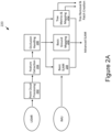
- Figures 2A , 2B , 2C , and 2D illustrate in more detail an example implementation of some of the aspects of Figure 1 .
- Figure 2A illustrates a basic SLAM process for LiDAR and IMU sensor data.
- the LiDAR data source is processed using point cloud processing 202, followed by feature extraction 204, and occlusion handling 206.
- the IMU sensor data is used to perform basic SLAM 208, basic ground mapping 210, and tree metrics & mapping 212.
- Figure 2B illustrates a continuation of Figure 2A , showing aspects of patch creation.
- the advanced SLAM processor 230 takes into account GPS data
- the Advanced SLAM processor 230 generates outputs for miscellaneous object detection 231, an advanced ground model 233, vegetation mapping 235, and removed tree detection 237.
- a patch creation sub-map 239 receives the outputs of the Advanced SLAM processor 230, miscellaneous object detection 231, advanced ground model 233, vegetation mapping 234, removed tree detection 237, and a patch creation signal from the basic SLAM 220.
- FIG. 2C shows aspects of a global mapper 255 to generate different types of maps and other information to generate real time operator guidance.
- a patch database 252 is accessed that in one implementation contains all the patched from all the machines across a forestry project lifecycle.
- 3 rd party maps 254 such as forestry project maps.
- the global map generation 256 in one implementation generated a unified tree map 258, a unified ground model 260, a unified vegetation map 262, unified miscellaneous objects 264, removed tree map 266, machine activities & paths 268, worked areas 270, and mapped areas seen/unseen 272. This mapping information is used to generate real time operator guidance.
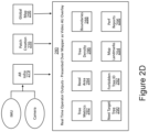
- Figure 2D illustrates an example of real time operator outputs 280 showing as an input, the camera video output and IMU data 279 for augmented reality data inputs, patch creation 220, and the global map 256.
- the real time operator outputs in one implementation are presented over mapper as a video AU overlay.
- Some examples of real time operator outputs include tree metrics 282, basal area 24, tree density 286, boundaries 288, next target tree 290, forbidden tree ID 292, map landmarks 294, and performance reports 296.
- FIG. 2A , 2B , 2C , and 2D it can be seen in Figures 2A , 2B , 2C , and 2D that various forms of map optimizations are performed, which can take into account the availability of GPS and IMU sensor data. Tree mapping is performed. Various optimization can be performed as implementation details.
- the patch generation takes into account various sources of information.For example, various optimizations may be performed for the patches to orient, overlap and lock together. Patch creation may in some implementations include storing a create patch in a database and calculating descriptors. Patches are associated with positions. Various constraints may be considered including GPU constraints and IMU odometery constraints on patch position and orientation. In one implementation, a loop closure condition is included, as discussed below in more detail.
- a scan is packed into a patch based on a threshold condition regarding a number and density of landmarks and an overlap condition with a priority patch is determined.
- a patch is linked to priority patches and known patches are adjusted to fit a new configuration of available landmarks.
- An algorithm leveraging a tree-based loop closure expedient / scan-to-map operation reduces a SLAM drift in environments where external position correction is denied (e.g., GPS denied environment and/or communications denied such that NTRIP corrections are unavailable).
- external position correction e.g., GPS denied environment and/or communications denied such that NTRIP corrections are unavailable.
- GPS accuracy may be reduced in heavily wooded areas and from hills and other obstructions.
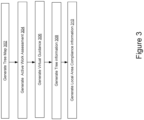
- Figure 302 is a flow chart of a general method.
- a tree map is generated.
- Various services may be provided based on the tree map. This may include generating an active work assessment in block 304 by providing information comparing what has been done versus what remains to be done in a project plan, generating virtual guidance 306 on what an operator should do, generating tree information on an individual tree 308, such as information on its size or is otherwise a candidate for removal, local are compliance information regarding a status or actions to be taken in a particular area based on the tree map and project information. More generally, a wide variety of different types of information may be generated to aid project information leveraging off the tree map.
- the real-time video and LiDAR processing system performs range finding and object dimensional analysis within the field of view of the LiDAR system. These analyses produce a map of distances, sizes, and when joined with the positioning system a location for each object observed in the immediate vicinity of the vehicle. This system presents the data about the objects into a live video feed, overlaying annotations directly into the spatial location of the video frame, of the local environment.
- LiDAR returns provide a direction and a distance (via time of flight) to all objects in the return radius of the active forestry machine. These returns are clustered into objects where subsequent scans improve the modelled form in two ways: increased confidence in the physical shape and increased perspective as the object moves relative to the LiDAR unit. This provides additional information to fill in all 3 dimensions of the identified objects such that better decisions can be made in the future while enabling immediate decisions to be made several times per second.
- a forestry management plan may specify either or both minimum and maximum tree sizes to harvest.
- a bucketing method iteratively refines the diameter at breast height of that tree in order to improve the confidence in the height above ground for the DBH (Diameter Breast Height) measurement. Refining the diameter estimate is important due to consideration like the shape of the tree, which may be out-of-round. Also, the diameter as observed via edge finding in the LiDAR returns.
- the earliest scans begin by identifying a candidate tree, improve with additional observations to resolve the diameter (e.g., into a 2" variance bucket as an example), then as more information removes uncertainty on either or both of the height to make the measurement and the diameter at that point of measurement the likely range in the measured size is reduced to +-0.5", +-0.25" and eventually to 0.1".
- the bucketing size may be implemented as a configurable parameter.
- Empirical tests demonstrated a capability to find the 2" bucket at 50-80' and usually refining down to 0.1" uncertainty as the vehicle passes by the tree (leaving the camera's 120-degree field of view, although the diameter refinement continues outside the field of view of the camera, although the LiDAR has a 360 degree field of view).
- These are example buckets and other buckets could be used if desired.
- This approach allows the operator to triage which trees are worth learning more about as candidates for harvesting without holding back information until final certainty is achieved. This has impacts on operator decision making and speed in performance of the work.
- the real-time LiDAR processing system preforms an assessment of the area covered by the stems of trees within a unit area of analysis, e.g. a basal area calculation generating a metric in units of area per area describing, for example, the fraction of an acre that is comprised by the wood of trees when measured at Breast Height (4'6" on the uphill side of the stem).
- Direct digitalization of the traditional practices does not result in a full stand measurement of basal area, rather than performing samples of the underlying stand inventory.
- the diameter measurement in one implementation is based on an algorithm for finding correct height for diameter measurements based on ground points from lidar and a ground point under machine.
- the ground points may be occluded, sloped, or otherwise difficult to distinguish.
- the measurement height can be any number of traditional forestry heights such as Diameter at Breast Height (4'6" above ground on the uphill side of the tree) or Diameter at Stump Height (4" above the ground).
- a method of measuring from different directions includes a statistical estimation per direction, and statistical combination of visible and invisible directions to arrive at an accurate estimation of the true diameter at the given height, and over the height of the stem a measure of the volume.
- the conventional approach includes selection of radii for sample plots, kind, and size.
- the conventional approach picks which trees to include or exclude from the sample plots.
- the computed basal area for a stand is sensitive to systematic inclusions or exclusions, which are decisions different survey teams make using different standards.
- a LiDAR based survey performed by the system 150 is not a sampling technique. It is a full measurement of the stand referenced to a fixed georeferenced partition.
- the direct assessment of trees is a complete census of the underlying stand inventory.
- the outputs of the various manual measurement techniques can be reproduced from the full stand census, but with a digitalized system we need not discard information in order to make the computations more tractable.
- LiDAR unit as mounted on the machine, surveys every part of the stand where work is performed. During this survey everything within range of the LIDAR's laser is counted and modeled to create a full census of the stand.
- the range may vary by density of the forest and performance of the laser unit, but usually sits in the range from 20-150m.
- the scanning occurs at least 5 times per second, building up a real time model of the landscape as the vehicle moves through it, providing census level stand information for all places where work may be performed (without spending effort in places where work will not be performed, as per other broadcast LiDAR techniques like backpack, drone, or aerial scans performed as part of the pre-project planning process).
- This full survey approach avoids the great cost of making multiple trips through the project area in order to characterize, plan, and summarize the work later performed, but collects those data at the point of change as the work is being performed.
- the initial information is collected as the machine approaches and the post-work state is characterized as the machine moves on into the stand.
- This repeatability resolves one dimension of the field survey practices question, leaving only uncertainty in the alignment of the location to the globe (e.g. GPS uncertainty).
- a real-time LiDAR processing system that performs a SLAM computation to extend geolocation into heavy canopy or steep terrain where other geolocation systems have difficulty (e.g. GPS).
- This SLAM computation may leverage the static position of the tree or features of a detailed ground contour to refine and extend the positional accuracy well beyond the limits of GPS under the same conditions.
- This SLAM system uses a combination of point cloud processing and landmark position processing in a way that optimizes computational power and scalability.
- Two stage algorithm depends on the patch algorithm which works in real-time to convert a local point cloud into a small map of landmarks to serve as a map patch.
- These patches are comprised of several features and landmarks, the configuration and orientation of objects allow the next patch to lock into the neighboring patches to build up a wider fabric for navigation and orientation.
- the real-time scanning places the landmarks into a location and configuration with respect to each other. Once reduced to landmarks, orientations, and sizes, the patches are much easier to manipulate and refine through connections to other patches as subsequent patches are created and better resolution on existing patches are achieved.
- the following computation runs 5 times per second:
- Lidar scans returned from objects are received.
- the detected objects are coalesced into a collection of landmarks oriented with one another.
- the scan is packed into a patch if a sufficient number of and density of landmark is achieved and a desired overlap with a prior patch is reached. This corresponds to a set of threshold conditions for packaging a scan into a patch.
- the patch is linked to prior patches and known patches are adjusted to fit the new configuration of available landmarks.
- new data for existing patches is incorporated.
- n memory is cleared for new LIDAR object returns.
- the real-time LiDAR processing system performs a SLAM calculation that leverages precisely compressed modeling of feature and landmarks in the positional refinement.
- SLAM Simultaneous Localization and Mapping
- SLAM Simultaneous Localization and Mapping
- Tree SLAM algorithm computes patches quickly, such that long running loop closures are unnecessary, compresses those landmark maps into patches, links patches to one another, and then orients the LiDAR's position to the reference framework of landmarks built up in the fabric of patches to perform a real-time SLAM that does not rely on exhaustive point cloud processing or loop closure as per conventional SLAM algorithms.
- the objects identified happen to be trees in our context, but any recognizable objects that move slowly or in known ways with respect to the LiDAR unit are suitable for this short range iterative positional refinement.
- the memory working set is guarded through the use of abstract patches, simplifications of the point cloud, rather than full fidelity point clouds.
- the cycle cadence for the algorithm is fast, which avoids managing large working sets for point cloud data, tearing, or streaking in laser returns, and the need for more intensive computations like conventional loop closure.
- the tree SLAM uses the Iterative closest point (ICP) algorithm for minimizing the difference between two sets of points.
- ICP Iterative closest point
- detected objects are added from the most recent last LIDAR scan to the map.
- Objects e.g., trees
- New detections are matched to the local tree map using ICP in block 514.
- decision block 516 a decision is made whether the match is good. If not, the process either trees again in block 518 or makes a determination to stop (e.g., stopping after a certain number of tries). If the results are yes, a constraint is added to the factor graph to represent the movement that was just recorded in block 520.
- the local tree map is updated in block 522. Information on existing trees is updated in block 524.
- the real-time LiDAR processing system observes the objects in the immediate vicinity of the vehicle, mutations in that operating environment, and produces a full map of objects (tree map) of the project area capturing the initial conditions, final conditions, and detailed data about all transformations within that project area (such as location, size, and kind of mutation).
- the tree map (a catalog of landmark objects that happen to be trees) contains physical metadata about the landmark, e.g. location, height, diameter, species, health, age, and other relevant data attached to a stand inventory, as well as a temporal view of the project area. In one implementation, this is used to construct a before and after catalog and census of all objects (trees) in the project area.
- a real-time LiDAR processing system that incorporates external knowledge, such as aerial lidar, internal algorithms, such as SLAM, and real-time sensing of terrain and objects to create reference patches where vehicle position within that patch is known and locking new patches to these georeferenced prior patches to extend the region of geopositional certainty arbitrarily into the network of interlocking patches.
- the position initialization leverages external information like aerial LiDAR to geolocate landmarks within the operating area or ground contour information collected before the project as well as real-time observations from within the project area, such as locations and configurations of objects (landmarks like trees), GPS information from satellite systems, IMU (inertial measurement unit) data to help contextualize bulk vehicle movements, and our SLAM implementations to cross-validate the vehicle's actual position through weaknesses or outages of the various contributing features for the true position.
- external information like aerial LiDAR to geolocate landmarks within the operating area or ground contour information collected before the project as well as real-time observations from within the project area, such as locations and configurations of objects (landmarks like trees), GPS information from satellite systems, IMU (inertial measurement unit) data to help contextualize bulk vehicle movements, and our SLAM implementations to cross-validate the vehicle's actual position through weaknesses or outages of the various contributing features for the true position.
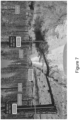
- Figure 7 is an illustration of the system of real-time video and data overlay in real-world testing.
- Two landmark trees are shown with an overlay showing the DBH for each tree as a horizontal line.
- selecting two trees e.g., ID 25014 and ID 25016 causes the system to display the distance between them (in this example, 27.0 feet).
- magenta labels note the positions and sizes of identified trees and selecting any two causes the system to present the computed distance between those selected objects.
- the LiDAR object identification is translated into annotations into the live video feed.
- This user experience involves the combination of interaction, experience, synthesis, observation, and analysis to put in front of the operator the required context to make sense of the immediate surroundings, bringing lacking expertise and awareness to the forestry machine operator such that they may more easily achieve their project goals.
- Figures 9 , 10 , and 11 illustrate an implementation of a user interface presenting the operator of the forestry machine with important context relating to the real time evaluation of the work remaining to be done, the location of the machine with respect to the work, and an interactive view of the immediate environment augmented through the on-machine sensing that this system interacts with.
- This display updates as the machine moves through the project area, interacting with boundaries for instance.
- This display updates the colors of the hexagons located around the machine to reflect ongoing work performed by the machine evaluated against the management goals of the project, for instance.
- these visualizations are color coded and scaled to the distance and position of the machine, supporting first person and overhead orienting views.
- the real time local area compliance assessment combines sensing data about the operational environment with expectations given the planning and design of the work being performed to evaluate the current state of compliance with the end-goals and objectives for the project.
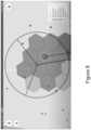
- Figure 8 illustrates a compliance grading with several colored levels allowing real time, graduated, feedback to the operator to assess the approach to target for the work being performed.
- red hexagons have a basal area above 110 ft 2 /acre and are far above the target for the final project basal area.
- Blue hexagons have a basal area below 50 ft 2 /acre and are far below the target for the final project basal area.
- Green and yellow hexagons are on the low and high sides of the target basal area for the project representing the ranges 50-80 and 80-110 ft 2 /acre. These ranges support the operator reaching the target without being overly constrained such that the operator cannot swiftly complete the work.
- the scaling coincides with a 30' radius sample plot. The size of the circles corresponds to individual tree diameters.
- each noted tree diameter is proportional and scaled to the measured diameter for those trees in the observed environment around the forestry vehicle.
- Figure 8 is based on a methodology of taking the real time mapping data in combination with the work plan in order to generate a visualization that shows where the vehicle is, where it has been, and what state of completeness was last observed for each of those areas.
- the scale of evaluation is basal area, the area of the trees per unit area divided by the unit area, and is evaluated over a variety of unit scales such as 1 hexagon, 7 hexagons, 1 acre, etc. This real-time evaluation allows an operator to work against an inspection target that is non-trivial for a human to assess while controlling a forestry vehicle.
- a sensor kit may be suitable for a variety of kinds of data collection, or they may work separately or together across time to build up a deeper understanding of the forest environment.
- the data collected may be purely observational, or combined with real-time analysis to produce judgements meant to favor specific project outcomes, such as the evaluation of the current state against the desired state in order to provide timely feedback to the operator of the forestry vehicle as it executes work across the project area.
- Figure 9 illustrates an example of a screen capture from an active forestry project from the operator guidance tablet from inside the cab of the vehicle with an overlay of trees to scale (brown dots) providing a visual indication of their size and density, and in this example, reference unit hexagons color coded to highlight regions where trees are too close to one another as reflected through the project requirements and representative of the project objectives.
- same sensor kit could be mounted on a variety of human, machine, or animal-based platforms, including backpack versions, drone, UTV, and unconventional platforms (donkeys, snowmobiles).
- these area appraisals are recorded and reported as the forestry work advances through the project area, providing planning guidance for subsequent physical inspection as well as replayability for subsequent remote assessment of project compliance against project objectives.
- a camera video view is overlayed by relevant metadata to provide the forestry equipment operator in the immediate environment and optionally contrast those observations against the project objectives and requirements.
- a bulk measurement of trees within the field of view and near the machine toolhead is displayed over in the video. This presentation can include a color coding for trees that do not qualify for the project requirements, such as a directive to "cut no tree over 21" in diameter," or simply as shown the bulk diameter measurement of the identified trees in range.
- the assessment here includes factors such as species identification, size, health, spacing, volume, position, etc. but is concentrated on visual confirmation of qualification or intent prior to the performance of each forestry action.
- Each identified activity is recorded and logged via the system including the video feed, so that stakeholders outside the project execution environment can review and assess the work as it was performed.
- a tablet display is mounted near the forestry vehicle controller's chair.
- Alternative implementations may include a heads-up display or overlay and integration into the visual feed for a remote teleops control system.
- the example of a user interface includes metadata and metrics assessed from the sensed environment in real time.
- the labels for notable objects, trees here, include an identifier for that object, distance from the machine, and diameter at breast height for that object. Interacting with one of the objects allows the operator to select another object and perform various relevant measurements, the results of which are presented in the user interface.
- the labels in the user interface may display observed physical characteristics assessed by the onboard sensors and alternatively may show the determination of judgements on which work ought to be performed or avoided to achieve the expectations given the known project requirements and desired outcomes.
- the unique tree identifier assessed and recorded by the hardware sensors connect observed characteristics of the project before, during, and after completion of the work to a 3rd party record of that work that may be queried offline and audited for compliance without mandating physical detection of all anomalies in the field.
- the tree-by-tree accountability outlined here extends to the operator as automatic work tracking, saving a regular manual progress reporting task, and supports an in-line inspection facilitating a single pass of execution to reach compliance on the forestry project.
- This real-time feedback links the initial project execution to the corrective action, avoiding long and contentious feedback cycles.
- the system records the position and identity of each notable object within the project area including locations where the kinds of work were performed, such as the removal of trees.
- the automated data collection records physical measurements, analyzes operator and forestry vehicle behaviors to attribute working activity, and automatically reports these metadata to local supervisors, the cloud, and a management portal accessible over the internet.
- visualization of virtual boundaries in combination with in-cab feedback are combined to provide the operator with awareness of the project layout.
- the visualization may make use of a tablet facing the operator, audio tones, and vibratory alerts to convey proximity, coincidence, and violation of project boundaries.
- Different kinds of boundary for instance watercourse buffers, project boundaries, and wildlife or ecology zones, may convey their presence through a different combination of the elements in part or together.
- a user interface display shows a dot with an arrow indicating the facing of a forestry vehicle just inside the boundary of an exclusion zone defined as part of the project layout definition.
- a colorful notification is displayed warning the operator that the forestry vehicle is in a place where no forestry vehicle should be.
- the path leading to this location crosses an open area and starts from the bottom of the screen on the outside of this project area, demonstrating the elements of virtual project layout and real time operator guidance.
- a process can generally be considered a self-consistent sequence of steps leading to a result.
- the steps may involve physical manipulations of physical quantities. These quantities take the form of electrical or magnetic signals capable of being stored, transferred, combined, compared, and otherwise manipulated. These signals may be referred to as being in the form of bits, values, elements, symbols, characters, terms, numbers, or the like.
- the disclosed technologies may also relate to an apparatus for performing the operations herein.
- This apparatus may be specially constructed for the required purposes, or it may include a general-purpose computer selectively activated or reconfigured by a computer program stored in the computer.
- the disclosed technologies can take the form of an entirely hardware implementation, an entirely software implementation or an implementation containing both software and hardware elements.
- the technology is implemented in software, which includes, but is not limited to, firmware, resident software, microcode, etc.
- a computer-usable or computer-readable medium can be any apparatus that can contain, store, communicate, propagate, or transport the program for use by or in connection with the instruction execution system, apparatus, or device.
- a computing system or data processing system suitable for storing and/or executing program code will include at least one processor (e.g., a hardware processor) coupled directly or indirectly to memory elements through a system bus.
- the memory elements can include local memory employed during actual execution of the program code, bulk storage, and cache memories which provide temporary storage of at least some program code in order to reduce the number of times code must be retrieved from bulk storage during execution.
- I/O devices including, but not limited to, keyboards, displays, pointing devices, etc.
- I/O controllers can be coupled to the system either directly or through intervening I/O controllers.
- modules, routines, features, attributes, methodologies, and other aspects of the present technology can be implemented as software, hardware, firmware, or any combination of the three.
- a component an example of which is a module
- the component can be implemented as a standalone program, as part of a larger program, as a plurality of separate programs, as a statically or dynamically linked library, as a kernel loadable module, as a device driver, and/or in every and any other way known now or in the future in computer programming.
- the present techniques and technologies are in no way limited to implementation in any specific programming language, or for any specific operating system or environment. Accordingly, the disclosure of the present techniques and technologies is intended to be illustrative, but not limiting.
Landscapes
- Engineering & Computer Science (AREA)
- Physics & Mathematics (AREA)
- General Physics & Mathematics (AREA)
- Remote Sensing (AREA)
- Radar, Positioning & Navigation (AREA)
- Computer Networks & Wireless Communication (AREA)
- Theoretical Computer Science (AREA)
- Electromagnetism (AREA)
- Multimedia (AREA)
- Health & Medical Sciences (AREA)
- General Health & Medical Sciences (AREA)
- Business, Economics & Management (AREA)
- Life Sciences & Earth Sciences (AREA)
- Marketing (AREA)
- Tourism & Hospitality (AREA)
- Primary Health Care (AREA)
- General Business, Economics & Management (AREA)
- Economics (AREA)
- Human Resources & Organizations (AREA)
- Strategic Management (AREA)
- Mining & Mineral Resources (AREA)
- Marine Sciences & Fisheries (AREA)
- Animal Husbandry (AREA)
- Computational Linguistics (AREA)
- Agronomy & Crop Science (AREA)
- Navigation (AREA)
- Instructional Devices (AREA)
- Processing Or Creating Images (AREA)
Applications Claiming Priority (1)
| Application Number | Priority Date | Filing Date | Title |
|---|---|---|---|
| US202363592853P | 2023-10-24 | 2023-10-24 |
Publications (1)
| Publication Number | Publication Date |
|---|---|
| EP4546013A1 true EP4546013A1 (de) | 2025-04-30 |
Family
ID=93283912
Family Applications (1)
| Application Number | Title | Priority Date | Filing Date |
|---|---|---|---|
| EP24208708.8A Pending EP4546013A1 (de) | 2023-10-24 | 2024-10-24 | System und verfahren zur forstwirtschaftsprojektkonformität und -ausführung |
Country Status (3)
| Country | Link |
|---|---|
| US (1) | US20250130331A1 (de) |
| EP (1) | EP4546013A1 (de) |
| CA (1) | CA3256576A1 (de) |
Families Citing this family (1)
| Publication number | Priority date | Publication date | Assignee | Title |
|---|---|---|---|---|
| CN120949255A (zh) * | 2025-10-17 | 2025-11-14 | 西北农林科技大学深圳研究院 | 手持式林区样地标定测绘装置及方法 |
Citations (3)
| Publication number | Priority date | Publication date | Assignee | Title |
|---|---|---|---|---|
| US20150269438A1 (en) * | 2014-03-18 | 2015-09-24 | Sri International | Real-time system for multi-modal 3d geospatial mapping, object recognition, scene annotation and analytics |
| US20200066034A1 (en) * | 2017-02-27 | 2020-02-27 | Katam Technologies Ab | Improved forest surveying |
| US20220117215A1 (en) * | 2020-10-16 | 2022-04-21 | Verdant Robotics, Inc. | Autonomous detection and treatment of agricultural objects via precision treatment delivery system |
-
2024
- 2024-10-24 EP EP24208708.8A patent/EP4546013A1/de active Pending
- 2024-10-24 CA CA3256576A patent/CA3256576A1/en active Pending
- 2024-10-24 US US18/925,866 patent/US20250130331A1/en active Pending
Patent Citations (3)
| Publication number | Priority date | Publication date | Assignee | Title |
|---|---|---|---|---|
| US20150269438A1 (en) * | 2014-03-18 | 2015-09-24 | Sri International | Real-time system for multi-modal 3d geospatial mapping, object recognition, scene annotation and analytics |
| US20200066034A1 (en) * | 2017-02-27 | 2020-02-27 | Katam Technologies Ab | Improved forest surveying |
| US20220117215A1 (en) * | 2020-10-16 | 2022-04-21 | Verdant Robotics, Inc. | Autonomous detection and treatment of agricultural objects via precision treatment delivery system |
Non-Patent Citations (1)
| Title |
|---|
| JIAN TANG ET AL: "SLAM-Aided Stem Mapping for Forest Inventory with Small-Footprint Mobile LiDAR", FORESTS, vol. 6, no. 12, 17 December 2015 (2015-12-17), pages 4588 - 4606, XP055402717, DOI: 10.3390/f6124390 * |
Also Published As
| Publication number | Publication date |
|---|---|
| US20250130331A1 (en) | 2025-04-24 |
| CA3256576A1 (en) | 2025-05-21 |
Similar Documents
| Publication | Publication Date | Title |
|---|---|---|
| Fassnacht et al. | Remote sensing in forestry: current challenges, considerations and directions | |
| US20240331072A1 (en) | Vegetation management system and vegetation management method | |
| Hermosilla et al. | Regional detection, characterization, and attribution of annual forest change from 1984 to 2012 using Landsat-derived time-series metrics | |
| US11676375B2 (en) | System and process for integrative computational soil mapping | |
| CN118887767B (zh) | 一种基于卫星物联网的森林火灾预警方法、系统及设备 | |
| Herrero-Huerta et al. | Automatic tree parameter extraction by a Mobile LiDAR System in an urban context | |
| CN117272191B (zh) | 一种城市地下空间智能测绘方法及系统 | |
| US8818031B1 (en) | Utility pole geotagger | |
| KR102239393B1 (ko) | 원격탐사 기반 수종 분류 시스템 및 방법 | |
| US12480922B2 (en) | Methods and systems for characterizing methane emission employing mobile methane emission detection | |
| Vatandaşlar et al. | Assessing the potential of mobile laser scanning for stand-level forest inventories in near-natural forests | |
| Sumnall et al. | Analysis of a lidar voxel-derived vertical profile at the plot and individual tree scales for the estimation of forest canopy layer characteristics | |
| EP4546013A1 (de) | System und verfahren zur forstwirtschaftsprojektkonformität und -ausführung | |
| Prendes et al. | An algorithm for the automatic parametrization of wood volume equations from Terrestrial Laser Scanning point clouds: application in Pinus pinaster | |
| Hosseini et al. | Influence of plot and sample sizes on aboveground biomass estimations in plantation forests using very high resolution stereo satellite imagery | |
| Jing et al. | Efficient point cloud corrections for mobile monitoring applications using road/rail-side infrastructure | |
| Puletti et al. | Enhancing wall-to-wall forest structure mapping through detailed co-registration of airborne and terrestrial laser scanning data in Mediterranean forests | |
| CN119942366A (zh) | 荒漠草原灌木地上生物量卫星遥感估算方法 | |
| Cosgrove et al. | Using the full potential of Airborne Laser Scanning (aerial LiDAR) in wildlife research | |
| CN117152532A (zh) | 输电线路区段标注方法、装置、计算机设备和存储介质 | |
| To et al. | Carbon stock estimation at scale from aerial and satellite imagery | |
| Sanchez | Automated unmanned systems and data analytics for In-field digital crop phenotyping | |
| Capobianco et al. | Assessing the Accuracy of Global Tree Loss Products Using Dual-Date Airborne LiDAR in Estonia | |
| CN119672548B (zh) | 一种基于激光slam的仓储特征学习方法及系统 | |
| Olson et al. | The application of intra-canopy photogrammetry for assessing crown health attributes in sugar maple (Acer saccharum Marsh.) |
Legal Events
| Date | Code | Title | Description |
|---|---|---|---|
| PUAI | Public reference made under article 153(3) epc to a published international application that has entered the european phase |
Free format text: ORIGINAL CODE: 0009012 |
|
| STAA | Information on the status of an ep patent application or granted ep patent |
Free format text: STATUS: THE APPLICATION HAS BEEN PUBLISHED |
|
| AK | Designated contracting states |
Kind code of ref document: A1 Designated state(s): AL AT BE BG CH CY CZ DE DK EE ES FI FR GB GR HR HU IE IS IT LI LT LU LV MC ME MK MT NL NO PL PT RO RS SE SI SK SM TR |
|
| STAA | Information on the status of an ep patent application or granted ep patent |
Free format text: STATUS: REQUEST FOR EXAMINATION WAS MADE |
|
| 17P | Request for examination filed |
Effective date: 20251029 |