EP4546127A1 - Procédé de génération d'interface et dispositif électronique - Google Patents
Procédé de génération d'interface et dispositif électronique Download PDFInfo
- Publication number
- EP4546127A1 EP4546127A1 EP23879000.0A EP23879000A EP4546127A1 EP 4546127 A1 EP4546127 A1 EP 4546127A1 EP 23879000 A EP23879000 A EP 23879000A EP 4546127 A1 EP4546127 A1 EP 4546127A1
- Authority
- EP
- European Patent Office
- Prior art keywords
- bitmap
- interface
- animation
- electronic device
- application
- Prior art date
- Legal status (The legal status is an assumption and is not a legal conclusion. Google has not performed a legal analysis and makes no representation as to the accuracy of the status listed.)
- Pending
Links
Images















Classifications
-
- G—PHYSICS
- G06—COMPUTING OR CALCULATING; COUNTING
- G06F—ELECTRIC DIGITAL DATA PROCESSING
- G06F3/00—Input arrangements for transferring data to be processed into a form capable of being handled by the computer; Output arrangements for transferring data from processing unit to output unit, e.g. interface arrangements
- G06F3/01—Input arrangements or combined input and output arrangements for interaction between user and computer
- G06F3/048—Interaction techniques based on graphical user interfaces [GUI]
- G06F3/0487—Interaction techniques based on graphical user interfaces [GUI] using specific features provided by the input device, e.g. functions controlled by the rotation of a mouse with dual sensing arrangements, or of the nature of the input device, e.g. tap gestures based on pressure sensed by a digitiser
- G06F3/0488—Interaction techniques based on graphical user interfaces [GUI] using specific features provided by the input device, e.g. functions controlled by the rotation of a mouse with dual sensing arrangements, or of the nature of the input device, e.g. tap gestures based on pressure sensed by a digitiser using a touch-screen or digitiser, e.g. input of commands through traced gestures
- G06F3/04883—Interaction techniques based on graphical user interfaces [GUI] using specific features provided by the input device, e.g. functions controlled by the rotation of a mouse with dual sensing arrangements, or of the nature of the input device, e.g. tap gestures based on pressure sensed by a digitiser using a touch-screen or digitiser, e.g. input of commands through traced gestures for inputting data by handwriting, e.g. gesture or text
-
- G—PHYSICS
- G06—COMPUTING OR CALCULATING; COUNTING
- G06T—IMAGE DATA PROCESSING OR GENERATION, IN GENERAL
- G06T13/00—Animation
-
- G—PHYSICS
- G06—COMPUTING OR CALCULATING; COUNTING
- G06F—ELECTRIC DIGITAL DATA PROCESSING
- G06F3/00—Input arrangements for transferring data to be processed into a form capable of being handled by the computer; Output arrangements for transferring data from processing unit to output unit, e.g. interface arrangements
- G06F3/01—Input arrangements or combined input and output arrangements for interaction between user and computer
- G06F3/048—Interaction techniques based on graphical user interfaces [GUI]
- G06F3/0481—Interaction techniques based on graphical user interfaces [GUI] based on specific properties of the displayed interaction object or a metaphor-based environment, e.g. interaction with desktop elements like windows or icons, or assisted by a cursor's changing behaviour or appearance
-
- G—PHYSICS
- G06—COMPUTING OR CALCULATING; COUNTING
- G06F—ELECTRIC DIGITAL DATA PROCESSING
- G06F3/00—Input arrangements for transferring data to be processed into a form capable of being handled by the computer; Output arrangements for transferring data from processing unit to output unit, e.g. interface arrangements
- G06F3/01—Input arrangements or combined input and output arrangements for interaction between user and computer
- G06F3/048—Interaction techniques based on graphical user interfaces [GUI]
- G06F3/0481—Interaction techniques based on graphical user interfaces [GUI] based on specific properties of the displayed interaction object or a metaphor-based environment, e.g. interaction with desktop elements like windows or icons, or assisted by a cursor's changing behaviour or appearance
- G06F3/0482—Interaction with lists of selectable items, e.g. menus
-
- G—PHYSICS
- G06—COMPUTING OR CALCULATING; COUNTING
- G06F—ELECTRIC DIGITAL DATA PROCESSING
- G06F3/00—Input arrangements for transferring data to be processed into a form capable of being handled by the computer; Output arrangements for transferring data from processing unit to output unit, e.g. interface arrangements
- G06F3/01—Input arrangements or combined input and output arrangements for interaction between user and computer
- G06F3/048—Interaction techniques based on graphical user interfaces [GUI]
- G06F3/0484—Interaction techniques based on graphical user interfaces [GUI] for the control of specific functions or operations, e.g. selecting or manipulating an object, an image or a displayed text element, setting a parameter value or selecting a range
-
- G—PHYSICS
- G06—COMPUTING OR CALCULATING; COUNTING
- G06F—ELECTRIC DIGITAL DATA PROCESSING
- G06F3/00—Input arrangements for transferring data to be processed into a form capable of being handled by the computer; Output arrangements for transferring data from processing unit to output unit, e.g. interface arrangements
- G06F3/01—Input arrangements or combined input and output arrangements for interaction between user and computer
- G06F3/048—Interaction techniques based on graphical user interfaces [GUI]
- G06F3/0484—Interaction techniques based on graphical user interfaces [GUI] for the control of specific functions or operations, e.g. selecting or manipulating an object, an image or a displayed text element, setting a parameter value or selecting a range
- G06F3/04845—Interaction techniques based on graphical user interfaces [GUI] for the control of specific functions or operations, e.g. selecting or manipulating an object, an image or a displayed text element, setting a parameter value or selecting a range for image manipulation, e.g. dragging, rotation, expansion or change of colour
-
- G—PHYSICS
- G06—COMPUTING OR CALCULATING; COUNTING
- G06F—ELECTRIC DIGITAL DATA PROCESSING
- G06F3/00—Input arrangements for transferring data to be processed into a form capable of being handled by the computer; Output arrangements for transferring data from processing unit to output unit, e.g. interface arrangements
- G06F3/01—Input arrangements or combined input and output arrangements for interaction between user and computer
- G06F3/048—Interaction techniques based on graphical user interfaces [GUI]
- G06F3/0484—Interaction techniques based on graphical user interfaces [GUI] for the control of specific functions or operations, e.g. selecting or manipulating an object, an image or a displayed text element, setting a parameter value or selecting a range
- G06F3/0485—Scrolling or panning
-
- G—PHYSICS
- G06—COMPUTING OR CALCULATING; COUNTING
- G06T—IMAGE DATA PROCESSING OR GENERATION, IN GENERAL
- G06T3/00—Geometric image transformations in the plane of the image
- G06T3/40—Scaling of whole images or parts thereof, e.g. expanding or contracting
-
- G—PHYSICS
- G06—COMPUTING OR CALCULATING; COUNTING
- G06F—ELECTRIC DIGITAL DATA PROCESSING
- G06F2203/00—Indexing scheme relating to G06F3/00 - G06F3/048
- G06F2203/048—Indexing scheme relating to G06F3/048
- G06F2203/04803—Split screen, i.e. subdividing the display area or the window area into separate subareas
-
- G—PHYSICS
- G06—COMPUTING OR CALCULATING; COUNTING
- G06F—ELECTRIC DIGITAL DATA PROCESSING
- G06F9/00—Arrangements for program control, e.g. control units
- G06F9/06—Arrangements for program control, e.g. control units using stored programs, i.e. using an internal store of processing equipment to receive or retain programs
- G06F9/44—Arrangements for executing specific programs
- G06F9/451—Execution arrangements for user interfaces
-
- G—PHYSICS
- G06—COMPUTING OR CALCULATING; COUNTING
- G06T—IMAGE DATA PROCESSING OR GENERATION, IN GENERAL
- G06T2200/00—Indexing scheme for image data processing or generation, in general
- G06T2200/24—Indexing scheme for image data processing or generation, in general involving graphical user interfaces [GUIs]
Definitions
- This application relates to the technical field, and in particular, to an interface generation method and an electronic device.
- resolution and a refresh rate of a screen of an electronic device are increasingly high.
- the resolution of the screen affects pixels included in one frame of interface, and the refresh rate affects time for generating one frame of interface.
- the electronic device Before the electronic device displays a 1 st frame of interface, the electronic device needs to spend a computing resource to generate the 1 st frame of interface. Before the electronic device displays a 2 nd frame of interface, the electronic device needs to spend a computing resource again to generate the 2 nd frame of interface.
- This application discloses an interface generation method and an electronic device, and relates to the field of electronic technologies.
- embodiments of this application provide an interface generation method and an electronic device.
- an extended bitmap is generated in advance, and a plurality of frames of interfaces in the animation process is generated by performing operations such as capturing and/or splicing.
- the electronic device does not need to traverse a view and generate a bitmap for a plurality of times.
- embodiments of this application provide an interface generation method, applied to an electronic device, where a first application runs on the electronic device, and the method includes: The electronic device generates a first bitmap by using the first application after receiving a first operation, where the first bitmap includes display data corresponding to at least two frames of interfaces of the first application in a first animation, and the first operation is used to trigger the electronic device to display the first animation by using the first application; the electronic device obtains the at least two frames of interfaces of the first animation through capturing performed on the first bitmap; and the electronic device displays the first animation.
- a bitmap including display data of a plurality of frames of interfaces for example, the first bitmap
- the first bitmap is generated in advance based on continuity of the interface in an animation.
- the electronic device does not need to perform operations such as view traversal and bitmap generation by using a UI thread and a render thread, so that load of the application is reduced and an energy efficiency ratio of interface generation is improved.
- the first animation is a sliding animation
- that the electronic device generates the first bitmap by using the first application after receiving the first operation specifically includes: after the electronic device receives the first operation and determines that the first animation is the sliding animation, the electronic device modifies a size of a window of the first application, so that the size of the window of the first application changes from a first size to a second size, where the second size is greater than the first size; and the application generates the first bitmap based on the second size.
- a manner of generating the first bitmap is to modify the size of the window of the application, where a modified size is greater than the unmodified size.
- the window of the application becomes larger, and therefore, more content can be displayed, where the more content is content required by the first bitmap.
- the view related to the first animation includes a list view; when the size of the window of the first application is the first size, the list view includes a first list entry, and when the size of the window of the first application is the second size, the list view includes the first list entry and a second list entry; and on an M th frame of interface of the first animation, the first list entry is displayed and the second list entry is not displayed, and on an N th frame of interface of the first animation effect, the second list entry is displayed and the first list entry is not displayed, where M is not equal to N, and the M th frame of interface and the N th frame of interface belong to the at least two frames of interfaces.
- the list view when an interface of the first application includes the list view and the list view changes in the sliding animation, before the size of the window of the application is modified, the list view includes the first list entry but does not include the second list entry due to a limitation of a size of the list view; and after the size of the window of the application is changed, the size of the list view changes accordingly, and the list view includes the second list entry and the first list entry.
- an animation display process when it is determined, based on animation logic, that the second list entry needs to be displayed, the second list entry only needs to be captured from the first bitmap for being sent for display.
- the first animation is a sliding animation
- that the electronic device generates the first bitmap by using the first application after receiving the first operation specifically includes: The application modifies a size of a first view, where the first view is a view whose display content in the first animation changes, and a modified size of the first view is greater than the unmodified size of the first view; and the application generates the first bitmap based on the modified first view.
- a manner of generating the first bitmap is to modify a size of a view related to the sliding animation. After the size of the view is modified, the view includes content that needs to be displayed in the view on a plurality of frames of interfaces, to generate the first bitmap.
- the first view is a list view; before the first view is modified, the first view includes a first list entry, and after the first view is modified, the first view includes the first list entry and a second list entry; and on an M th frame of interface of the first animation effect, the first list entry is displayed and the second list entry is not displayed, and on an N th frame of interface of the first animation effect, the second list entry is displayed and the first list entry is not displayed, where M is not equal to N, and the M th frame of interface and the N th frame of interface belong to the at least two frames of interfaces.
- the list view includes the first list entry but does not include the second list entry due to a limitation of a size of the list view; when the size of the list view is modified, the list view may include more list entries, for example, the second list entry; and in the animation display process, when it is determined, based on animation logic, that the second list entry needs to be displayed, the second list entry only needs to be captured from the first bitmap for being sent for display.
- the first bitmap is generated by using the application specifically includes: The application extends a first view, where the first view is a view whose display content changes within duration of the first animation effect, and one or more sub-views are added to the extended first view; and the application generates the first bitmap based on the extended first view
- a manner of generating the first bitmap is to add a sub-view to a view related to the animation, where display content corresponding to the sub-view is content that is not displayed on an interface other than a current frame in the animation process, for example, content displayed on a next frame of interface.
- the method before the first bitmap is generated by using the first application, and after the electronic device receives the first operation, the method further includes: The electronic device determines a dynamic area of an interface of the first animation by using the first application, where the first bitmap includes display data corresponding to a dynamic area of the at least two frames of interfaces of the first animation; and that the electronic device obtains the at least two frames of interfaces of the first animation through capturing performed on the first bitmap specifically includes: The electronic device captures a second bitmap from the first bitmap, where the second bitmap includes display data of a dynamic area on a first interface, and the first interface belongs to the at least two frames of interfaces of the first animation; and the electronic device generates the first interface based on the second bitmap.
- a dynamic area and a static area may be obtained through division, where the dynamic area is an area in which display content changes, and the dynamic area may be the same as or different from a dirty area.
- the first bitmap needs to include at least display data of the dynamic area on the plurality of frames of interfaces in the animation process, so that splicing and/or capturing are/is performed on the first bitmap to generate the plurality of frames of interfaces in the animation process.
- the method further includes: The electronic device generates a third bitmap by using the first application, where the third bitmap is a static area in the first animation, and the static area is an area in which display content on an interface of the first application in the first animation does not change; and that the electronic device generates the first interface based on the second bitmap specifically includes: The electronic device generates the first interface based on the second bitmap and the third bitmap.
- the static area and the dynamic area on the current frame of interface need to be spliced together, to generate one frame of interface in the animation process.
- the first bitmap further includes display data of a static area in the first animation, and the static area is an area in which display content on an interface of the first application in the first animation does not change.
- the static area may be in the first bitmap, or may not be in the first bitmap, but is obtained from another place, for example, captured from a previous frame of interface.
- display content of different interfaces in the animation process is different. Therefore, capturing needs to be performed on different areas in the extended bitmap, to obtain display data used to generate the different interfaces in the animation process.
- the method further includes: In the process of generating the J th frame of interface of the first animation, the electronic device captures a fourth bitmap from the first bitmap, where the fourth bitmap is display data of a third area in the first bitmap; the electronic device splices the fourth bitmap and the third bitmap to generate a fifth bitmap, where the fifth bitmap corresponds to the J th frame of interface; and the electronic device displays the J th frame of interface of the first animation based on the fifth bitmap.
- one frame of interface in the animation process may be obtained by splicing display content in a plurality of different areas in the first bitmap.
- the method further includes: The electronic device obtains, by using an application server, content carried on a view in the first area in the first bitmap, where the content carried on the view is a text, an image, and/or a video.
- the first bitmap includes display content of a next frame of interface to be displayed in the animation process, and display content of another frame of interface in the animation process, content carried on all views may not be loaded when the first bitmap is generated. Further, to reduce load of generating the first bitmap, content carried on all the views is not loaded, to improve a speed of generating the first bitmap.
- the first bitmap is used to generate a 1 st frame of interface to a K th frame of interface of the first animation, and K is an integer greater than 1; and after the application generates the first bitmap, and before the electronic device displays the K th frame of interface, the method further includes: The application generates a sixth bitmap, where the sixth bitmap is used to generate a (K+1) th frame of interface to an L th frame of interface of the first animation, and L is an integer greater than (K+1).
- the sixth bitmap is the 2 nd extended bitmap, that is, the interface in the animation process may be displayed by using a plurality of extended bitmaps. In this way, a size of the first bitmap can be reduced, and load of generating the first bitmap can be reduced; and the animation may be interrupted by another operation of the user, and extended bitmaps of all interfaces in the corresponding animation process may not be generated.
- the first operation is a sliding operation.
- embodiments of this application provide an interface generation method, where the method is applied to an electronic device, and the method includes: A UI thread of an application generates a first render tree after receiving a trigger event of a sliding animation and after receiving a vertical synchronizing signal, where the first render tree includes a drawing instruction used to generate a plurality of frames of images in a first animation; a first process or a render thread of the application generates a first bitmap based on the first render tree after receiving the first render tree, where the first process is different from a process of the application; the first process or the render thread of the application captures a first area in the first bitmap to obtain a 1 st frame of image in a first animation process; the 1 st frame of image in the first animation process is displayed; the first process or the render thread of the application captures a second area in the first bitmap to obtain a 2 nd frame of image in the first animation process, where the second area is different from the first area; and the 2 nd frame of image in
- the electronic device after determining that an animation needs to be displayed, the electronic device generates an extended bitmap, and different areas in the extended bitmap are captured to display different interfaces, so that quantities of times that the UI thread of the application performs traversal view and the render thread performs rendering can be reduced, to improve an energy efficiency ratio of an interface.
- that the UI thread of the application generates the first render tree specifically includes: The UI thread of the application determines that the animation is the sliding animation; and the UI thread of the application modifies a property of a view and/or a view hierarchy of the view based on the sliding animation, so that display content corresponding to the modified view includes display content corresponding to the view of the 1 st frame of interface and the view of the 2 nd frame of interface in a display process of the sliding animation; and the UI thread of the application generates the first render tree after executing measurement method invocation, layout method invocation, and drawing and recording method invocation.
- the extended bitmap may be generated in a plurality of manners. For example, the property of the view and/or the view hierarchy of the view are/is modified, to generate the first render tree, where the first render tree is content corresponding to the extended bitmap.
- the method further includes: The application loads display content in the first area in the first bitmap from an application server, where the display content in the first area is a text, a video, or an image, the first area is located in the third bitmap, and the first area is not located in the second bitmap.
- the electronic device may load only content carried on a view in a display area that needs to be displayed, to reduce a delay of generating the extended bitmap.
- embodiments of this application provide an electronic device, where the electronic device includes one or more processors and a memory, the memory is coupled to the one or more processors, the memory is configured to store computer program code, the computer program code includes computer instructions, and the one or more processors call the computer instructions to enable the electronic device to perform the following content:
- the electronic device generates a first bitmap by using the first application after receiving a first operation, where the first bitmap includes display data corresponding to at least two frames of interfaces of the first application in a first animation, and the first operation is used to trigger the electronic device to display the first animation by using the first application; the electronic device obtains the at least two frames of interfaces of the first animation through capturing performed on the first bitmap; and the electronic device displays the first animation.
- the one or more processors are specifically configured to call the computer instructions to enable the electronic device to perform the following content:
- the first animation is a sliding animation; after the electronic device receives the first operation and determines that the first animation is the sliding animation, the electronic device modifies a size of a window of the first application, so that the size of the window of the first application changes from a first size to a second size, where the second size is greater than the first size; and the application generates the first bitmap based on the second size.
- the view related to the first animation includes a list view; when the size of the window of the first application is the first size, the list view includes a first list entry, and when the size of the window of the first application is the second size, the list view includes the first list entry and a second list entry; and on an M th frame of interface of the first animation, the first list entry is displayed and the second list entry is not displayed, and on an N th frame of interface of the first animation effect, the second list entry is displayed and the first list entry is not displayed, where M is not equal to N, and the M th frame of interface and the N th frame of interface belong to the at least two frames of interfaces.
- the one or more processors are specifically configured to call the computer instructions to enable the electronic device to perform the following content:
- the first animation is a sliding animation;
- the application modifies a size of a first view, where the first view is a view whose display content in the first animation changes, and a modified size of the first view is greater than the unmodified size of the first view; and the application generates the first bitmap based on the modified first view.
- the first view is a list view; before the first view is modified, the first view includes a first list entry, and after the first view is modified, the first view includes the first list entry and a second list entry; and on an M th frame of interface of the first animation effect, the first list entry is displayed and the second list entry is not displayed, and on an N th frame of interface of the first animation effect, the second list entry is displayed and the first list entry is not displayed, where M is not equal to N, and the M th frame of interface and the N th frame of interface belong to the at least two frames of interfaces.
- the one or more processors are specifically configured to call the computer instructions to enable the electronic device to perform the following content:
- the application extends a first view, where the first view is a view whose display content changes within duration of the first animation effect, and one or more sub-views are added to the extended first view; and the application generates the first bitmap based on the extended first view
- the one or more processors are specifically configured to call the computer instruction to enable the electronic device to perform the following content:
- the electronic device determines a dynamic area of an interface of the first animation by using the first application, and the first bitmap includes display data corresponding to a dynamic area of the at least two frames of interfaces of the first animation; and the one or more processors are further configured to call the computer instructions to enable the electronic device to perform the following content:
- the electronic device captures a second bitmap from the first bitmap, where the second bitmap includes display data of a dynamic area on a first interface, and the first interface belongs to the at least two frames of interfaces of the first animation; and the electronic device generates the first interface based on the second bitmap.
- the one or more processors are further configured to call the computer instructions to enable the electronic device to perform the following content:
- the electronic device generates a third bitmap by using the first application, where the third bitmap is a static area in the first animation, and the static area is an area in which display content on an interface of the first application in the first animation does not change; and the one or more processors are specifically configured to call the computer instructions to enable the electronic device to perform the following content:
- the electronic device generates the first interface based on the second bitmap and the third bitmap.
- the first bitmap further includes display data of a static area in the first animation, and the static area is an area in which display content on an interface of the first application in the first animation does not change.
- the one or more processors are further configured to call the computer instructions to enable the electronic device to perform the following content:
- the electronic device captures a fourth bitmap from the first bitmap, where the fourth bitmap is display data of a third area in the first bitmap; the electronic device splices the fourth bitmap and the third bitmap to generate a fifth bitmap, where the fifth bitmap corresponds to the J th frame of interface; and the electronic device displays the J th frame of interface of the first animation based on the fifth bitmap.
- the one or more processors are further configured to call the computer instructions to enable the electronic device to perform the following content:
- the electronic device obtains, by using an application server, content carried on a view in the first area in the first bitmap, where the content carried on the view is a text, an image, and/or a video.
- the one or more processors are further configured to call the computer instructions to enable the electronic device to perform the following content:
- the first bitmap is used to generate a 1 st frame of interface to a K th frame of interface of the first animation, and K is an integer greater than 1; and the application generates a sixth bitmap, where the sixth bitmap is used to generate a (K+1) th frame of interface to an L th frame of interface of the first animation, and L is an integer greater than (K+1).
- the first operation is a sliding operation.
- embodiments of this application provide an electronic device, where the electronic device includes one or more processors and a memory, the memory is coupled to the one or more processors, the memory is configured to store computer program code, the computer program code includes computer instructions, and the one or more processors call the computer instructions to enable the electronic device to perform the following content:
- a UI thread of an application generates a first render tree after receiving a trigger event of a sliding animation and after receiving a vertical synchronizing signal, where the first render tree includes a drawing instruction used to generate a plurality of frames of images in a first animation;
- a first process or a render thread of the application generates a first bitmap based on the first render tree after receiving the first render tree, where the first process is different from a process of the application;
- the first process or the render thread of the application captures a first area in the first bitmap to obtain a 1 st frame of image in a first animation process; the 1 st frame of image in the first animation process is displayed;
- the one or more processors are specifically configured to call the computer instructions to enable the electronic device to perform the following content:
- a UI thread of the application modifies a property of a view and/or a view hierarchy of the view based on the sliding animation, so that display content corresponding to the modified view includes display content corresponding to a view on the 1 st frame of interface and a view on the 2 nd frame of interface in a display process of the sliding animation; and the UI thread of the application generates the first render tree after executing measurement method invocation, layout method invocation, and drawing and recording method invocation.
- the one or more processors are further configured to call the computer instruction to enable the electronic device to perform the following content:
- the application loads display content in the first area in the first bitmap from an application server, where the display content in the first area is a text, a video, or an image, the first area is located in a third bitmap, and the first area is not located in a second bitmap.
- embodiments of this application provide a chip system, where the chip system is used for an electronic device, the chip system includes one or more processors, and the processor is configured to call computer instructions to enable the electronic device to perform the method according to any one of the first aspect, the second aspect, the possible implementations of the first aspect, and the possible implementations of the second aspect.
- embodiments of this application provide a computer program product including instructions, where when the computer program product runs on an electronic device, the electronic device is enabled to perform the method described in any one of the first aspect, the second aspect, the possible implementations of the first aspect, and the possible implementations of the second aspect.
- embodiments of this application provide a computer-readable storage medium, including instructions, where when the instructions are run on an electronic device, the electronic device is enabled to perform the method described in any one of the first aspect, the second aspect, the possible implementations of the first aspect, and the possible implementations of the second aspect.
- the electronic device provided in the third aspect or the fourth aspect, the chip system provided in the fifth aspect, the computer program product provided in the sixth aspect, and the computer storage medium provided in the seventh aspect are all configured to perform the method provided in embodiments of this application. Therefore, for beneficial effect that can be achieved, refer to beneficial effect in the corresponding method. Details are not described herein again.
- first and second are merely intended for a purpose of description, and shall not be understood as an indication or implication of relative importance or implicit indication of a quantity of indicated technical features. Therefore, a feature limited by “first” or “second” may explicitly or implicitly include one or more features. In the descriptions of embodiments of this application, unless otherwise specified, "a plurality of" means two or more than two.
- a term "user interface (user interface, UI)" in the following embodiments of this application is a medium interface for interaction and information exchange between an application or an operating system and a user, and implements conversion between an internal form of information and a form that can be accepted by the user.
- the user interface is source code written in a specific computer language like Java or an extensible markup language (extensible markup language, XML). Interface source code is parsed and rendered on an electronic device, and is finally presented as content that can be identified by the user.
- the user interface is usually represented in a form of graphical user interface (graphical user interface, GUI), and is a user interface that is related to a computer operation and that is displayed in a graphic manner.
- GUI graphical user interface
- the user interface may be a visual interface element, for example, a text, an icon, a button, a menu, a tab, a text box, a dialog box, a status bar, a navigation bar, or a Widget that is displayed on a display of an electronic device.
- a visual interface element for example, a text, an icon, a button, a menu, a tab, a text box, a dialog box, a status bar, a navigation bar, or a Widget that is displayed on a display of an electronic device.
- the interface is used as the medium interface for interaction and information exchange between the application and the user.
- the electronic device needs to generate an interface (or an image) of an application for the foreground application.
- a frequency of the vertical synchronizing signal is related to a refresh rate of a screen of the electronic device. For example, the frequency of the vertical synchronizing signal is the same as the refresh rate of the screen of the electronic device.
- the electronic device needs to generate an interface of the application for the foreground application, to present the newly generated interface of the application to the user when the screen is refreshed.
- the application When the electronic device generates an interface of an application, the application needs to perform rendering to generate a bitmap (bitmap), and transfer the bitmap of the application to a surface flinger (SurfaceFlinger).
- bitmap bitmap
- SurfaceFlinger a surface flinger
- the application acts as a producer to draw and generate a bitmap, and stores the bitmap in a buffer queue (BufferQueue) provided by the surface flinger.
- BufferQueue a buffer queue
- the surface flinger acts as a consumer to continuously obtain, from the buffer queue, the bitmap generated by the application.
- the bitmap is located on a surface generated by the application. The surface is filled in the buffer queue.
- the surface flinger After the surface flinger obtains a bitmap of a visible application, the surface flinger and a hardware composer (Hardware Composer, HWC) determine a layer compositing manner in which a bitmap is used as a layer (layer).
- HWC Hardware Composer
- the surface flinger and/or the hardware composer After the surface flinger and/or the hardware composer perform/performs bitmap composition, the surface flinger and/or the hardware composer fill/fills, into a frame buffer (Frame Buffer), a bitmap obtained through composition and transfers the bitmap to a display subsystem (Display Subsystem, DSS). After obtaining the bitmap obtained through composition, the DSS may display the bitmap on the screen.
- the frame buffer may be an on-screen buffer (on-screen buffer).
- the bitmap may also be referred to as a layer on the surface flinger.
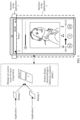
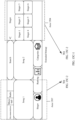
- FIG. 1 is a diagram of an example of generating an electronic device interface according to an embodiment of this application.
- an interface of an application 1 and an interface of an application 2 are displayed on a screen of an electronic device.
- the interface of the application 1 may be referred to as a status bar.
- the application 1 may be an operating system
- the application 2 may be a music application.
- the electronic device Before displaying the interface shown in FIG. 1 , the electronic device needs to separately and independently generate a bitmap of an application.
- the interface of the status bar is maintained by the operating system, that is, it may be considered that the application that generates a bitmap of the status bar is the operating system.
- the operating system transfers the bitmap 1 to a surface flinger; and after generating a bitmap 2, the music application transfers the bitmap 2 to the surface flinger.
- the bitmap 1 carries image information of the status bar
- the bitmap 2 carries image information of the music application.
- the surface flinger and/or a hardware composer After receiving the bitmap 1 and the bitmap 2, the surface flinger and/or a hardware composer perform/performs layer composition by using the bitmap 1 and the bitmap 2 as layers. Unless otherwise specified, a process in which the interface of the status bar or the like is generated and a process in which the interface of the status bar or the like participates in layer composition are not described in detail again in the following.
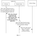
- FIG. 2 A process of generating a bitmap by an application is shown in FIG. 2 .
- FIG. 2 is a diagram of an example of generating a bitmap by an application according to an embodiment of this application.
- a UI thread traverses a view of an application, and stores a drawing operation of each view to a newly generated render tree.
- the UI thread (UI thread, UI Thread) makes a view hierarchy (view hierarchy) invalid.
- the UI thread traverses the view (view) of the application through measurement method invocation (measure()), layout method invocation (layout()), and drawing method invocation (draw()), determines and stores the drawing operation of each view, and records, into a drawing instruction list (displaylist) of a render node (RenderNode) of the render tree, the view and the drawing operation (for example, drawline) related to the view.
- Data stored in the drawing instruction list may be a drawing operation (DrawOP or DrawListOP) structure.
- the view (view) is a basic element that forms an application interface, and one control on the interface may correspond to one or more views.
- the UI thread of the application may further read, into a memory, content carried on the view, for example, an image carried on an image view (imageview), and a text carried on a text view (textview).
- the UI thread of the application determines an operation of reading, into the memory, the content carried on the view, and records the operation into the drawing instruction list.
- the drawing operation structure in the drawing instruction list may also be referred to as a drawing instruction.
- the drawing operation structure is a data structure, and is used to draw a graph, for example, draw a line, draw a rectangle, or draw a text.
- the drawing operation structure may be converted, by using a rendering engine, into API invocation of the image processing library, for example, interface invocation of an OpenGL ES library, a Vulkan library, or a Metal library.
- the drawline may be encapsulated as a DrawLineOp.
- the DrawLineOp is a data structure, and the data structure includes information about drawing data such as a length and a width of a line.
- the DrawLineOp may be further encapsulated as interface invocation of the OpenGL ES library, the Vulkan library, or the Metal library, to obtain a GPU instruction.
- the OpenGL ES library, the Vulkan library, and the Metal library may be collectively referred to as the image processing library or a graphics rendering library.
- the electronic device In a process of generating a frame of interface, the electronic device generates a rendering instruction by using the OpenGL ES library, the Vulkan library, or the Metal library.
- the image processing library provides a graphics rendering API, driver support, and the like.
- the DrawOP may be stored in a stack of the application in a chained data structure.
- the drawing instruction list may be a buffer.
- the buffer records all drawing operation structures included in a frame of interface of the application or identifiers, such as, an address and a sequence number of all drawing operations included in a frame of interface of the application.
- a plurality of render trees corresponding to the plurality of windows need to be generated independently.
- the render tree is generated by the UI thread and is used to generate a data structure on the application interface.
- the render tree may include a plurality of render nodes, and each render node includes a render property and a drawing instruction list.
- the render tree records a part or all of information about generating a frame of interface of the application.
- the UI thread may traverse only a view of a dirty area (which may also be referred to as an area that needs to be redrawn), to generate a differential render tree.
- the render thread may determine, based on the differential render tree and a render tree used for rendering of a previous frame, a render tree that needs to be used for rendering an interface of a current frame.
- S202 The UI thread synchronizes the render tree to the render thread, where the render tree is located in the stack of the application.
- the UI thread transfers/synchronizes the render tree to the render thread (Render Thread), where the render tree is located in the stack (stack) of a process corresponding to the application.
- S203 The render thread executes a drawing instruction in the render tree, to generate the bitmap.
- the render thread first obtains a hardware canvas (HardwareCanvas) and performs the drawing operation in the render tree on the hardware canvas, to generate the bitmap.
- the hardware canvas is located on a surface of the application, and the surface carries the bitmap or data that is in another format and that is used to store image information.
- the render thread sends the generated bitmap to the surface flinger through the surface for participating in layer composition.
- Step S201 may be considered as a construction phase, and is mainly responsible for determining properties such as a size, a location, and transparency of each view in the application.
- the drawline in the view may be encapsulated into a DrawLineOp during construction.
- the DrawLineOp includes the drawing data such as the length and the width of the line, may further include interface invocation corresponding to the DrawLineOp of an underlying graphics processing library, and is used to call the underlying graphics library for generation of the bitmap in a rendering phase.
- step S203 is the rendering phase, and is mainly responsible for traversing the render node of the render tree, and performing the drawing operation on each render node, to generate the bitmap on the hardware canvas.
- the render thread calls the underlying graphics processing library like the OpenGL ES library, the Vulkan library, or the Metal library, to call a GPU to complete rendering, so as to generate the bitmap.
- content displayed by the application usually changes continuously rather than discontinuously, that is, same display content may generally appear on a plurality of consecutive frames of interfaces, for example, as shown in FIG. 3A-1 to FIG. 3B in the following.
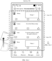
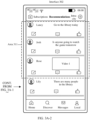
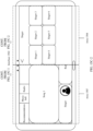
- FIG. 3A-1 to FIG. 3B are diagrams of an example of interfaces according to an embodiment of this application.
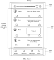
- an interface displayed by the electronic device changes from an interface 301 to an interface 302.
- the interface 301 By comparing the interface 301 with the interface 302, it can be learned that, after the electronic device receives the sliding operation, in a process in which the interface displayed by the electronic device changes, content displayed in an area 312 changes, and therefore, the area 312 is a dirty area.
- display content in an area 310 on the interface 301 and display content in an area 311 on the interface 302 are the same display content, that is, only a location of a part of the display content in the dirty area changes, but a view hierarchy of the part of the display content and content such as an image and a text carried on a view do not change.
- an area 313 and an area 314 other than the area 312 do not change, and therefore, the area 313 and the area 314 are not dirty areas.
- FIG. 4 is a diagram of an example of a process in which an electronic device generates the interfaces shown in FIG. 3A-1 to FIG. 3B according to an embodiment of this application.
- a process of generating the A th frame of interface by the electronic device is shown as 1, 2, 3, and 4 in FIG. 4 ; and a process of generating the (A+B) th frame of interface by the electronic device is shown as 5, 6, 7, and 8 in FIG. 4 .
- the A th frame of interface may be the interface 301 in FIG. 3A-1 and FIG. 3A-2
- 1 and 5 in FIG. 4 both indicate that a UI thread of an application traverses the dirty area, to generate a differential render tree (alternatively, the UI thread of the application traverses all the areas, to generate a new render tree); 2 and 6 in FIG. 4 indicate that a render thread of the application generates a new render tree based on the differential render tree and a render tree corresponding to a previous frame of interface, and then calls a GPU to perform rendering to generate a bitmap (if the render thread receives the new render tree, the new render tree is directly used to perform rendering); 3 and 7 in FIG. 4 indicate that a surface flinger and/or a hardware composer perform/performs layer composition by using the bitmap as a layer; and 4 and 8 in FIG. 4 indicate a process of sending and display performed by a display subsystem.
- the UI thread of the application may also traverse the dirty area, to generate the differential render tree, resulting in wasting of a resource of the UI thread and increasing of power consumption of the electronic device; and in the sliding process, in 2 and 4 in FIG. 4 , display content in the area 314 and display content in the area 313 do not change, and the bitmap generated by the render thread includes the same display content (namely, the display content in the area 314 and the area 313), resulting in wasting of a resource of the render thread and increasing of power consumption of the electronic device.
- embodiments of this application provide an interface generation method and an electronic device, so that an energy efficiency ratio of generating the plurality of consecutive frames of interfaces by the electronic device can be improved.
- an extended bitmap is generated in advance, and in an animation duration process, the UI thread does not need to traverse the dirty area or all the areas, the UI thread may not synchronize the render tree to the render thread, the render thread may not perform rendering to generate the bitmap, and the surface flinger and/or the hardware composer perform/performs operations such as cropping and/or splicing on the extended bitmap, to generate a next frame of interface.
- the extended bitmap includes image information or display content in a dirty area on a plurality of frames of interfaces in the animation duration process, and the extended bitmap does not have redundancy.
- the extended bitmap may also be referred to as a first bitmap.
- the animation may include sliding.
- the animation duration process is at least two frames of interfaces.
- a new extended bitmap is generated.
- the extended bitmap is generated in advance, and in the animation duration process, the UI thread no longer traverses the dirty area, the render thread no longer performs corresponding rendering, and the surface flinger and/or the hardware composer perform/performs operations such as capturing and/or splicing on the extended bitmap, to generate the plurality of frames of interfaces in the animation duration process.
- the interface of the application includes a dirty area and a non-dirty area, and content in the non-dirty area is generated by the render thread at least once in an entire animation process.
- the surface flinger and/or the hardware composer may further perform operation like splicing on the bitmap that carries the content in the non-dirty area.
- the electronic device may generate one or more frames of extended bitmaps.
- a static area (for example, the area 313 and the area 314 in FIG. 3B ) bitmap and the extended bitmap are generated in advance, and in the animation duration process, the UI thread does not perform traversal, the render thread does not perform corresponding rendering, and the surface flinger and/or the hardware composer perform/performs operations such as capturing and/or splicing on the extended bitmap and the static area bitmap, to generate the plurality of frames of interfaces in the animation duration process.
- a static area is an area includes a view that does not change on the plurality of frames of interfaces in the animation duration process.
- the UI thread no longer traverses same display content in the dirty area of the previous frame and the dirty area of the current frame
- the render thread no longer render the same content in the dirty area of the previous frame and the dirty area of the current frame
- the surface flinger and/or the hardware composer perform/performs operations such as capturing and/or splicing on a dirty area bitmap, to generate the plurality of frames of interfaces in the animation duration process.
- the UI thread traverses only a differential dirty area, the render thread renders the differential dirty area, and the surface flinger and/or the hardware composer perform/performs operations such as splicing and/or cropping on a bitmap corresponding to the differential dirty area and a bitmap corresponding to the previous frame of interface, to generate the plurality of frames of interfaces in the animation duration process.
- the differential dirty area is an area in which display content in the dirty area of the current frame is different from display content in the dirty area of the previous frame.
- the UI thread transfers, to the render thread, one or more parameters used to determine change logic of the animation.
- the render thread updates the render tree, and then performs corresponding rendering.
- the bitmap corresponding to the interface of the application is not generated by the render thread of the application, but is generated by a render process independent of the application.
- the render process may be referred to as a unified render process (UniRender).
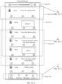
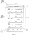
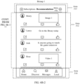
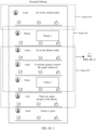
- FIG. 5A to FIG. 5C-2 are diagrams of an example of generating a plurality of frames of interfaces in an animation process based on an extended bitmap according to an embodiment of this application.
- the UI thread of the application may generate a render tree corresponding to the extended bitmap, and transfer or synchronize the render tree to the render thread or the render process to generate the extended bitmap, where the extended bitmap is shown in FIG. 5A .
- the extended bitmap includes the area 312, the area 313, the area 314, and an area 315.
- the generated extended bitmap does not include an otiose area.
- the extended bitmap may not include an area 316, that is, the extended bitmap is extended in the sliding direction instead of a non-sliding direction relative to a bitmap that is generated by the application render thread and that corresponds to one frame of interface.
- bitmap 1 corresponding to the interface 301 is shown in FIG. 5B-1 and FIG. 5B-2 , where the bitmap 1 includes the area 312, the area 313, and the area 314 of the extended bitmap.
- bitmap 2 corresponding to the interface 302 is shown in FIG. 5C-1 and FIG. 5C-2 , where the bitmap 2 includes the area 315, the area 313, and the area 314 of the extended bitmap.
- the UI thread of the application does not need to traverse the view to generate the render tree or the differential render tree, and the render thread or the render process does not need to generate a bitmap, so that a calculation amount of the electronic device in the animation process is reduced; and the UI thread and the render thread or the render process do not need to participate in generation of the plurality of frames of interfaces in the animation process, and only the surface flinger and/or the hardware composer need/needs to perform cropping and splicing on the extended bitmap, so that a probability of animation freezing is reduced, and an energy efficiency ratio of interface generation is improved.
- FIG. 6A to FIG. 6C-2 are diagrams of another example of generating a plurality of frames of interfaces in an animation process based on an extended bitmap according to an embodiment of this application.
- the UI thread of the application may generate the extended bitmap, where the extended bitmap is shown in FIG. 6A .
- the extended bitmap includes the area 316, the area 312, and the area 315.
- the generated extended bitmap does not include an otiose area.
- the extended bitmap may not include the area 316, that is, the extended bitmap is extended in the sliding direction instead of a non-sliding direction relative to a bitmap that is generated by the normal application render thread and that corresponds to one frame of interface.
- bitmap 1 corresponding to the interface 301 is shown in FIG. 6B-1 and FIG. 6B-2 , where the bitmap 1 includes the area 312 of the extended bitmap.
- bitmap 2 corresponding to the interface 302 is shown in FIG. 6C-1 and FIG. 6C-2 , where the bitmap 2 includes the area 315 of the extended bitmap.
- the surface flinger and/or the hardware composer may receive a static bitmap that is generated by the render thread or the render process and that corresponds to the area 313 and the area 314, and then perform operations such as cropping and/or splicing on the static bitmap and the extended bitmap, to generate the bitmap 1 or the bitmap 2.
- the UI thread may declare the static area (namely, the area 313 and the area 314), so that the render thread or the render process, and the surface flinger and/or the hardware composer retain image information such as a bitmap corresponding to the area.
- the surface flinger and/or the hardware composer may generate the bitmap 1 or the bitmap 2 based on the extended bitmap and the static bitmap.
- the display content of the render tree or the differential render tree generated by the UI thread of the application is in the extended bitmap, and in this way, the UI thread of the application does not need to perform traversal to generate the render tree or the differential render tree, so that a calculation amount of the electronic device in the animation process is reduced; and the UI thread does not need to participate in generation of the plurality of frames of interfaces in the animation process, and only the surface flinger and/or the hardware composer need/needs to perform cropping and splicing on the bitmap, so that a probability of animation freezing is reduced.
- the bitmap corresponding to the static area is generated and stored for reuse, and therefore, the render thread or the render process does not need to generate a same bitmap in each frame. In this way, the calculation amount is reduced, the probability of animation freezing is reduced, and an energy efficiency ratio of interface generation is improved.
- the extended bitmap in FIG. 5A to FIG. 5C-2 is extension of the interface of the application
- the extended bitmap in FIG. 6A to FIG. 6C-2 is extension of the dirty area of the interface of the application. It is clear that, if only the dirty area is extended, a calculation amount and a delay of generating the extended bitmap can be reduced, and when a view hierarchy of the interface of the application is complex, a manner of generating a bitmap through capturing and/or splicing performed on the extended bitmap shown in FIG. 6A to FIG. 6C-2, is more convenient.
- FIG. 7A and FIG. 7B are a diagram of another example of generating a plurality of frames of interfaces in an animation process based on a bitmap corresponding to a differential dirty area according to an embodiment of this application.
- the UI thread of the application traverses only the differential dirty area to generate the differential render tree; and the render thread generates, based on the differential render tree, the bitmap corresponding to the differential dirty area.
- the bitmap corresponding to the differential dirty area is an area 317
- the bitmap corresponding to the interface 301 is a bitmap 1.
- the bitmap 1 includes the area 312, the area 313, and the area 314, where the area 312 includes an area 3121.
- the surface flinger and/or the hardware composer may perform operations such as splicing and/or cropping on the bitmap corresponding to the differential dirty area and the bitmap 1 corresponding to the previous frame of interface, to generate a bitmap 2, where the bitmap 2 is the bitmap corresponding to the interface 302.
- the bitmap 2 includes the area 313, the area 3121, the area 317, and the area 314.
- the area 3121, the area 313, and the area 314 are content captured from the bitmap 1 by the surface flinger and/or the hardware composer.
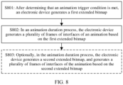
- FIG. 8 is a diagram of an example of a procedure of an interface generation method according to an embodiment of this application.
- the electronic device may send the input to an application, and the application determines whether the animation trigger condition is met.
- a trigger condition may be whether a sliding operation of the user is received.
- the sliding operation may be referred to as a first operation, and the sliding animation may be referred to as a first animation.
- an animation trigger event may be used by the application to determine whether the animation trigger condition is met.
- the application In a process of receiving the sliding operation of the user, or after the sliding operation of the user is received, or after the sliding operation of the user is received and a hand of the user has left a screen, for example, when an interface enters a habitual sliding state, the application generates the first extended bitmap.
- An extended bitmap is a bitmap whose size is larger than that of an original bitmap, or the extended bitmap is a bitmap whose coverage area is larger than that of the original bitmap, or the extended bitmap is a bitmap that covers more display content than the original bitmap.
- the extended bitmap includes only a dirty area
- the original bitmap means a part that corresponds to the dirty area and that is in the bitmap.
- the original bitmap is a bitmap corresponding to an interface before an animation starts, or a bitmap corresponding to the 1 st frame of interface displayed when the animation starts, or a bitmap corresponding to content that can be currently viewed by the user on the screen.
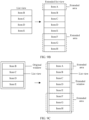
- FIG. 9A to FIG. 9C each are a diagram of an example of generating an extended bitmap according to an embodiment of this application.
- FIG. 9A A relationship between the extended bitmap and an original bitmap is shown in FIG. 9A , where the extended bitmap may include a part or all of the original bitmap and an extended area.
- the extended area may be an extension, in any direction, of the original bitmap.
- the extended area extends in a periphery direction; or as shown in (B) in FIG. 9A , the extended area extends in a top-down direction; or as shown in (B) in FIG. 9A , the extended area extends in a downward direction.
- the application may determine an extension direction of the extended area based on change logic of the animation, an identifier of the animation, or the like. For example, when the operation received by the application is an operation of sliding downward, it is determined that a sliding direction of the sliding animation is a direction of sliding downward, and then it is determined that the extended area is an extension, in the downward direction, of the original bitmap, as shown in (C) in FIG. 9A . In other words, the extended bitmap varies based on different triggered animations.
- the operation of sliding downward may also be referred to as a slide-up operation, that is, the sliding direction is from up to down.
- a relationship between a start location and an end location of the operation of sliding downward is as follows: On the screen, the start location is below the end location. For example, the start location of the operation of sliding downward is the bottom of the screen, and the end location of the operation of sliding downward is the top of the screen.
- the electronic device has a plurality of methods for generating an extended bitmap.
- the following uses a list view (listview) as an example to describe examples of two methods for generating an extended bitmap.
- the method for generating an extended bitmap is also applicable to other views such as a recyclerview, a grid view (gridview), and a customized view. This is not limited herein.
- the list view includes four sub-items (Item): Item B, Item C, Item D, and Item E.
- the list view may enable the extended area.
- the list view includes eight items: Item A, Item B, Item C, Item D, Item E, Item F, Item G, and Item H, where Item A, Item F, Item G, and Item H are items corresponding to the extended area.
- the list view may enable the extended area in a plurality of manners, for example, determine whether to enable the extended area based on a preview property or parameter.
- the UI thread may generate a drawing operation structure corresponding to each of Item A, Item F, Item G, and Item H to a render node of a render tree.
- a render thread may call a GPU to execute the drawing operation structure in the render tree, to generate the extended bitmap.
- source code of the list view may be modified at an application framework layer, to add the preview property or parameter to the list view, so as to enable the extended area.
- the application Before the animation starts or after the animation starts, the application enables the extended area based on the preview property or parameter. After the animation ends or a condition for generating an interface based on the extended bitmap is not met, the application invalidates the extended area based on the preview property or parameter.
- an extended list view may be implemented by modifying a height or a width of the list view.
- a property or a parameter of the view needs to be modified, for example, the preview property or parameter mentioned above, or the height or width of the view described above.
- a manner of extending a bitmap shown in FIG. 9C is to modify a size of a window of the application.
- a window management server notifies the application that a window used by the current application to present an interface changes from an original window to an extended window.
- the UI thread of the application performs traversal in a size of an extended window. Because the size of the extended window is greater than that of an original window, correspondingly, an absolute size occupied by the list view increases, and the list view may include more items.
- Added Items form the extended area, and the added Items are Item A, Item F, Item G, and Item H.
- the unmodified size of the window may be referred to as a first size, and the modified size of the window may be referred to as a second size.
- the animation ends or the condition for generating the interface based on the extended bitmap is not met, if the extended bitmap is implemented by using the extended window, the size of the window needs to be restored.
- the application may determine a size of the extended area, or configure a quantity of items included in the extended area.
- an operating system notifies the application of the size of the extended area, or the operating system configures a quantity of items included in the extended area of the application.
- the operating system may determine, based on a calculation amount for generating the 1 st frame of interface, current GPU load, current CPU load, an animation type, and/or the like, the size of the extended area and/or the quantity of items included in the extended area.
- the electronic device may generate the first extended bitmap in the manners shown in FIG. 9A to FIG. 9C .
- S802 In an animation duration process, the electronic device generates a plurality of frames of interfaces of the animation based on the first extended bitmap.
- the electronic device may perform operations such as splicing and/or cropping on the first extended bitmap, to generate the plurality of frames of interfaces of the animation, for example, as shown in FIG. 6B-1 and FIG. 6B-2 or FIG. 6C-1 and FIG. 6C-2 in the foregoing.
- the UI thread of the application may determine, based on animation logic, an area, in the first extended bitmap, of an interface that needs to be currently displayed, and notify a surface flinger and/or a hardware composer of the area.
- the UI thread of the application may further determine an area, in the first extended bitmap, of each frame of interface in the animation process.
- the parameters such as the sliding distance and/or the sliding speed of the sliding operation are located in the animation trigger event, and further are obtained by the UI thread.
- FIG. 10A and FIG. 10B are diagrams of an example of generating a plurality of frames of interfaces of an animation based on a first extended bitmap according to an embodiment of this application.
- the operating system transfers the operation to the application.
- the UI thread of the application receives the sliding operation, it is determined that the animation trigger condition is met.
- Generating the 1 st frame of interface in the animation process is , 2, 3, and 4 in FIG. 10A ; generating the 2 nd frame of interface in the animation process is 5 and 6 in FIG. 10A ; and generating the 3 rd frame of interface in the animation process is 7 and 8 in FIG. 10A .
- a process of generating the 1 st frame of interface in the animation process is as follows: After the UI thread of the application receives a vertical synchronizing signal, the UI thread of the application generates a render tree (or a differential render tree) corresponding to the first extended bitmap, as shown in 1 in FIG. 10A , and then transfers or synchronizes the render tree to the render thread or a render process. After the render thread or the render process receives the render tree, the first extended bitmap is generated, as shown in 2 in FIG. 10A , and then transfers the first extended bitmap to the surface flinger and/or the hardware composer.
- the surface flinger and/or the hardware composer perform/performs operations such as cropping and/or splicing on the first extended bitmap to generate a first captured bitmap, as shown in 3 in FIG. 10A , and then transfers the first captured bitmap to a display subsystem.
- the display subsystem may send the first captured bitmap for display, and display one frame of interface of the animation on the screen, as shown in 4 in FIG. 10A .
- a process of generating the 2 nd frame of interface in the animation process is as follows:
- the surface flinger and/or the hardware composer perform/performs operations such as cropping and/or splicing on the first extended bitmap to generate a second captured bitmap, as shown in 5 in FIG. 10A , and then transfers the second captured bitmap to the display subsystem.
- the display subsystem may send the second captured bitmap for display, and display one frame of interface of the animation on the screen, as shown in 6 in FIG. 10A .
- a process of generating the 3 rd frame of interface in the animation process is as follows:
- the surface flinger and/or the hardware composer perform/performs operations such as cropping and/or splicing on the first extended bitmap to generate a third captured bitmap, as shown in 7 in FIG. 10A , and then transfers the third captured bitmap to the display subsystem.
- the display subsystem may send the third captured bitmap for display, and display one frame of interface of the animation on the screen, as shown in 8 in FIG. 10A .
- an unchanged area may also participate in the operations such as cropping and/or splicing for generation of a captured bitmap in 3, 5, and 7, for example, the area 313 and the area 314 of the interface 301.
- the area 313 and the area 314 of the interface 301 may be captured from the extended bitmap in another captured area.
- deformation, blurring, and transparency adjustment may be performed on all or a part of the captured bitmap, to implement more complex animation effect.
- the application may send a message to the surface flinger and/or the hardware composer to indicate the surface flinger and/or the hardware composer to determine a relative location relationship between a captured area and the first extended bitmap, so as to determine the captured bitmap.
- the application may send a message to the surface flinger and/or the hardware composer each time after receiving the vertical synchronizing signal, where the message is used to determine a relative location relationship between the first extended bitmap and the captured area of a current frame of interface.
- the application may send a message to the surface flinger and/or the hardware composer when the animation starts or before the animation starts, where the message indicates a relative location relationship between the first extended bitmap and the captured area in the animation process.
- the message may include duration and a total variation of the animation, where a variation of each frame is determined by the surface flinger and/or the hardware composer, and the surface flinger and/or the hardware composer determine/determines the relative location relationship between the captured area and the first extended bitmap based on the variation of each frame.
- the message may include a variation of each frame and a total variation of the animation.
- the surface flinger and/or the hardware composer may also determine the relative location relationship between the captured area and the first extended bitmap based on the message.
- the view is a list view and the animation is the sliding animation to describe an example of a process in which the surface flinger and/or the hardware composer perform/performs operations such as cropping and/or splicing on the first extended bitmap to generate a captured bitmap like the first captured bitmap or the second captured bitmap.
- the surface flinger and/or the hardware composer determine/determines that the sliding distance is 0, and directly perform/performs capturing on the first extended bitmap based on the captured area to obtain the first captured bitmap.
- the surface flinger and/or the hardware composer adjust/adjusts a relative location between the captured area and the first extended bitmap, and perform/performs capturing on the first extended bitmap based on the captured area to obtain the second captured bitmap.
- the area 313 and the area 314 may be captured from the first extended bitmap, and then participate in a splicing process of the captured bitmap like the first captured bitmap or the second captured bitmap. A cropping process and splicing process of the area 313 or the area 314 are not shown in FIG. 10B .
- a captured bitmap in the animation duration process may be obtained through capturing performed on a plurality of captured areas and through splicing, or a captured bitmap may be obtained capturing is performed on a plurality of captured areas and then deformation, blurring, or the like is performed.
- the electronic device In the animation duration process, the electronic device generates a second extended bitmap, and generates a plurality of frames of interfaces of the animation based on the second extended bitmap.
- the electronic device may generate the second extended bitmap before the display content of the first extended bitmap cannot meet the animation requirement; or the electronic device may generate the second extended bitmap when determining that the display content of the first extended bitmap cannot meet the animation requirement.
- the second extended bitmap may also be referred to as a sixth bitmap.
- the application determines that the display content of the first extended bitmap cannot meet the animation requirement after first duration since the animation starts, and in this case, the UI thread of the application may generate the second extended bitmap within the first duration since the animation starts.
- the surface flinger and/or the hardware composer when the captured area is close to the bottom of the first extended bitmap (for example, when the operation is the operation of sliding downward, an area between a lower edge of the captured area and a lower edge of the first extended bitmap is less than X pixels) due to a change of the relative location of the first extended bitmap and the captured area, the surface flinger and/or the hardware composer sends a message to the UI thread of the application, where the message indicates the UI thread of the application to generate the second extended bitmap.
- the surface flinger and/or the hardware composer when the captured area exceeds the first extended bitmap, the surface flinger and/or the hardware composer sends a message to the UI thread of the application, where the message indicates the UI thread of the application to generate the second extended bitmap.
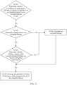
- FIG. 11 is a diagram of another example of a procedure of an interface generation method according to an embodiment of this application.
- S1101 Determine whether a condition for generating a plurality of frames of interfaces of an animation based on an extended bitmap is met.
- step S1102 is performed.
- the condition for generating the plurality of frames of interfaces of the animation based on the extended bitmap is met.
- generating the plurality of frames of interfaces of the animation based on the extended bitmap is supported, when it is determined that a triggered animation belongs to the some animation types, it is determined that the condition for generating the plurality of frames of interfaces of the animation based on the extended bitmap is met.
- step S1103 is performed; or if there is no extended bitmap, step S1104 is performed.
- S1103 Determine whether display content of the current extended bitmap can meet an animation requirement.
- step S1105 is performed; or if the display content of the current extended bitmap cannot meet the animation requirement, step S1104 is performed.
- S1104 Generate an extended bitmap.
- S1105 Generate the plurality of frames of interfaces of the animation based on the extended bitmap.
- an operating system may further provide an interface for an application, and the interface is used by the application to declare a static area and a dynamic area of an interface in an animation duration process.
- a bitmap corresponding to the static area is generated at most once in the animation duration process, that is, the static area is traversed and rendered at most once.
- an extended bitmap is generated according to the interface generation method shown in FIG. 8 or FIG. 10B in the animation duration process. In this case, the extended bitmap corresponds to the dynamic area and excludes the static area.
- FIG. 12A and FIG. 12B are diagrams of an example of generating a plurality of frames of interfaces of an animation based on an extended bitmap and a bitmap corresponding to a static area according to an embodiment of this application.
- the dynamic area is the same as a dirty area, that is, coverage areas are the same, and covered views are the same.
- the dynamic area is different from the dirty area.
- the area 313 and the area 314 form the static area.
- the area 313, the area 314, and a control 118 form the static area.
- a difference between FIG. 12A and FIG. 3B lies in that, an interface 104 and the interface 301 are different in that a display interface of the application further includes the control 118.
- the control 118 is a control used to return to the top of a list view, and during the sliding animation, the control 118 does not change. For example, returning to the top of the list view may also be referred to as resetting a focus to the top of the list view.
- FIG. 12A and FIG. 12B are diagrams of an example of generating a plurality of frames of interfaces of an animation based on an extended bitmap and a bitmap corresponding to a static area according to an embodiment of this application.
- a render process or a render thread generates the bitmap of the static area and a first extended bitmap. Then, after capturing a first captured bitmap from the first extended bitmap, a surface flinger and/or a hardware composer perform/performs splicing or layer composition on the first captured bitmap and the static area bitmap to generate a bitmap for being sent for display.
- the surface flinger and/or the hardware composer perform/performs splicing or layer composition on the second captured bitmap and the static area bitmap to generate a bitmap for being sent for display.
- a size of the static area bitmap may be the same as a size of a window of the application, where the bitmap corresponding to the static area has a blank area.
- the surface flinger and/or the hardware composer may perform layer composition on the captured bitmap and the static area bitmap to generate a bitmap for being sent for display.
- the size of the static area bitmap may be the same as a range of display content in the static area.
- the surface flinger and/or the hardware composer may perform splicing on the captured bitmap and the static area bitmap to generate a bitmap for being sent for display.
- the static area bitmap may be captured from one frame of interface before the animation starts.
- a location of the static area may be notified by the application to the surface flinger and/or the hardware composer.
- the static area is obtained through division in advance, so that the static area can be reused in the animation duration process, and repeated content does not need to be generated each time an extended bitmap is generated; and further, when there is a floating view on the interface of the application and content shielded by the floating view is the dirty area, the floating view falls into the static area, so that complexity of a splicing and/or cropping process performed by the surface flinger and/or the hardware composer can be reduced.
- a UI thread traverses only a differential dirty area
- the render thread or the render process performs corresponding rendering
- the surface flinger and/or the hardware composer perform/performs operations such as splicing and/or cropping on a bitmap corresponding to the differential dirty area and a bitmap corresponding to a previous frame of interface, to generate the plurality of frames of interfaces in the animation duration process, as shown in FIG. 13 .
- FIG. 13 is a diagram of an example of generating a plurality of frames of interfaces of an animation based on a bitmap corresponding to a differential dirty area according to an embodiment of this application.
- the render process or the render thread in a process of generating the A th frame of interface of the animation, the render process or the render thread generates the bitmap corresponding to the differential dirty area; and the render process or the render thread transfers the bitmap corresponding to the differential dirty area to the surface flinger and/or the hardware composer.
- the surface flinger and/or the hardware composer may obtain the first captured bitmap through captured area cropping from the bitmap corresponding to the previous frame of interface or a bitmap corresponding to a dirty area of the previous frame of interface, and then splice the first captured bitmap and the bitmap corresponding to the differential dirty area, and a bitmap obtained through splicing is a first splicing bitmap.
- the render process or the render thread of the application In a process of generating the (A+1) th frame of interface of the animation, the render process or the render thread of the application generates the bitmap corresponding to the differential dirty area; and the render process or the render thread transfers the bitmap corresponding to the differential dirty area to the surface flinger and/or the hardware composer.
- the surface flinger and/or the hardware composer may obtain the second captured bitmap through captured area cropping from the first splicing bitmap, and then splice the second captured bitmap and the bitmap corresponding to the differential dirty area, and a bitmap obtained through splicing is a second splicing bitmap.
- the first splicing bitmap and the second splicing bitmap are bitmaps for being sent for display, and are respectively a bitmap corresponding to the A th frame of interface of the animation and a bitmap corresponding to the (A+1) th frame of interface of the animation.
- the A th frame of interface of the animation is the interface 301, and a bitmap corresponding to the interface 301 is the bitmap 1 in FIG. 7A and FIG. 7B ; and the (A+1) th frame of interface of the animation is the interface 302, and a bitmap corresponding to the interface 302 is the bitmap 2 in FIG. 7A and FIG. 7B .
- the render thread or the render process may generate the bitmap corresponding to the differential dirty area, namely, the area 317 in FIG. 7A and FIG. 7B .
- the first splicing bitmap includes the area 312.
- the surface flinger and/or the hardware composer may obtain the second captured bitmap through captured area cropping from the first splicing bitmap, where the second captured bitmap includes the area 3 121.
- the surface flinger and/or the hardware composer splice/splices the second captured bitmap and the bitmap corresponding to the differential dirty area, and a bitmap obtained through splicing is the second splicing bitmap, where the second splicing bitmap includes the area 3121 and the area 317.
- the area 3121 and the area 317 form the area 312 in FIG. 3B , that is, the second splicing bitmap is the bitmap corresponding to the dirty area of the (A+1) th frame of interface of the animation.
- a bitmap corresponding to the non-dirty area may be obtained through cropping, or may be generated by the render thread or the render process.
- the differential dirty area is always less than or equal to the dirty area, so that a calculation amount and a delay of traversing a view by the application can be reduced, a calculation amount and a delay of the render thread or the render process can be reduced, and further, an energy efficiency ratio of interface generation can be improved.
- a calculation amount required for generating the extended bitmap needs to be greater than a calculation amount required for generating the original bitmap, and time required for generating the extended bitmap is also longer than time required for generating the original bitmap. Further, the calculation amount and the time for generating the extended bitmap may be reduced in a manner provided below.
- Delay loading means that when the extended bitmap is generated, the content carried on the view may not be loaded, loading of the content carried on the view may be delayed, and the content needs to be loaded at latest before the content is displayed.
- delay loading and/or pre-loading may be performed on the content carried on a view in all area of the extended bitmap.
- the pre-loading means that before the extended bitmap is generated, the content carried on the view in the extended bitmap may be obtained from an application server in advance and loaded to a cache.
- the delay loading means that content carried on a view may not be filled in a part of the view in the generated extended bitmap in a rendering phase. Because not all content in the extended bitmap may be displayed on one frame of interface, corresponding content may be filled in the view before the content of the view in the extended bitmap needs to be displayed.
- FIG. 14A and FIG. 14B are diagrams of an example of delay loading of an extended bitmap according to an embodiment of this application.
- the extended area of the extended bitmap includes a plurality of controls such as a control 1402, a control 1403, and a control 1404.
- the control 1402 is an image view
- the control 1403 is a text view
- the control 1404 is a text view.
- An image carried on the control 1402 needs to be obtained from the application server, and texts carried on the control 1403 and the control 1404 need to be obtained from the application server.
- the extended bitmap When the extended bitmap is generated, content carried on the control 1402, the control 1403, and/or the control 1404 is not downloaded from the application server first; and before the control 1402, the control 1403, and/or the control 1404 need/needs to be displayed, and after the UI thread (a sub-thread created by the UI thread) of the application initiates a request to the application server to obtain corresponding display content, the surface flinger and/or the hardware composer are/is used to fill the corresponding display content in the extended bitmap or in a corresponding location of the bitmap for being sent for display.
- the UI thread a sub-thread created by the UI thread
- the render thread or the render process may participate in loading of the content carried on the control, or may not participate in loading of the content carried on the control.
- a GPU may participate in loading of the content carried on the control, or may not participate in loading of the content carried on the control.
- Delay loading is shown in FIG. 14B .
- content of 1 to 8 refer to the foregoing text description in FIG. 10A . Details are not described herein again.
- content carried on a control in a non-extended area of the extended bitmap (content carried on a control on the 1 st frame of interface of the animation) needs to be obtained before t2.
- content carried on a control displayed on the 2 nd frame of interface of the animation in the extended area of the extended bitmap needs to be obtained before t3.
- content carried on a control displayed on the 3 rd frame of interface of the animation in the extended area of the extended bitmap needs to be obtained before t4.
- 4, 6, and 8 respectively indicate that a display subsystem sends the 1 st frame of interface of the animation for display, the display subsystem sends the 2 nd frame of interface of the animation for display, and the display subsystem sends the 3 rd frame of interface of the animation for display.
- the application may request, at any moment before t3, the application server to obtain images obtained on the control 1402, the control 1403, and/or the control 1404.
- t2, t3, and t4 are moments at which the application sequentially receives vertical synchronizing signals.
- an extended bitmap other than the first extended bitmap for example, a second extended bitmap, before the second extended bitmap is generated
- content carried on a control located in the second extended bitmap may be obtained in advance.
- delay loading and/or pre-loading are/is performed on an object like a media file that needs to be obtained from the application server, for example, an image or a text.
- the UI thread may determine, based on time and animation logic, whether a control is visible, to perform a further operation. For example, when a video view is invisible, playing of a multimedia data stream carried on the video view is paused.
- the control 1401 is a video view.
- the UI thread of the application determines whether the control 1401 is visible. After determining that the control 1401 is invisible, the application may pause a multimedia data stream corresponding to the control 1401, for example, pause video playing.
- the UI thread of the application may determine a location of the control 1401 on each frame of interface of the animation based on time and animation logic.
- the animation is a downward sliding animation.
- the animation logic includes a downward sliding height of each frame of interface.
- the UI thread may determine the location of the control 1401 in a process of performing view traversal, so that the UI thread can determine the location of the control 1401 on each frame of interface, and fill the multimedia data stream in the location of the control 1401 on each frame of interface.
- each frame of image data of the dynamic image is filled in a location of the image view on each frame of interface.
- interface generation in a switching animation process may also be implemented, as shown in FIG. 15A-1 to FIG. 15C-2 .
- FIG. 15A-1 to FIG. 15C-2 are diagrams of another example of generating a plurality of frames of interfaces in an animation process based on an extended bitmap according to an embodiment of this application.
- the electronic device displays an interface of a music application, as shown on an interface 1500.
- the interface 1500 includes a control 1503. After an operation of tapping the control 1503 by the user is received, an interface displayed by the electronic device changes from the interface 1500 to an interface 1501, and then changes from the interface 1501 to an interface 1502.
- a fragment (Fragment) is displayed in a floating manner on the interface, and the fragment is not completely displayed.
- the fragment is completely displayed, and is displayed on the interface in a floating manner.
- a display size of the fragment gradually increases.
- the electronic device may generate an extended bitmap, as shown in FIG. 15B-1 and FIG. 15B-2 .
- the extended bitmap includes an original bitmap and an area 1504, where the area 1504 is the extended area, and content displayed in the area 1504 is content displayed in the fragment.
- the area 1504 includes an area 1506, the original bitmap includes an area 1505, and the area 1505 and the area 1506 form the interface 1501.
- the surface flinger and/or the hardware composer may perform cropping on the extended bitmap to obtain the area 1505 and the area 1506 separately, and then perform splicing on the area 1505 and the area 1506 to obtain a bitmap corresponding to the interface 1501.
- the surface flinger and/or the hardware composer may perform cropping on the extended bitmap to obtain an area 1507 and the area 1504 separately, and then perform splicing on the area 1507 and the area 1504 to obtain a bitmap corresponding to the interface 1502.
- the interface 1500 is a static area, and the fragment is a dynamic area.
- a plurality of frames of interfaces in the switching animation are generated according to the foregoing interface generation method.
- content carried on a control in the fragment may be requested from the application server after it is determined that the extended bitmap needs to be generated.
- FIG. 16 is a diagram of an example of a software structure of an electronic device according to an embodiment of this application.
- a software system of the electronic device may use a layered architecture, an event-driven architecture, a microkernel architecture, a micro service architecture, or a cloud architecture.
- an Android system of the layered architecture is used as an example to illustrate the software structure of the electronic device.
- the layered architecture software is divided into several layers, and each layer has a clear role and task.
- the layers communicate with each other through a software interface.
- the Android system is divided into four layers: an application layer, an application framework layer, an Android runtime (Android runtime) and system library, and a kernel layer from top to bottom.
- the application layer may include a series of application packages.
- the application packages may include applications such as Camera, Gallery, Calendar, Phone, Map, Navigation, WLAN, Bluetooth, Music, Video, and Messages.
- the application framework layer provides an application programming interface (application programming interface, API) and a programming framework for an application at the application layer.
- the application framework layer includes some predefined functions.
- the application framework layer may include a window manager, a content provider, a view system, a phone manager, a resource manager, a notification manager, and the like.
- the window manager is configured to manage a window program.
- the window manager may obtain a size of a display, determine whether there is a status bar, perform screen locking, take a screenshot, or the like.
- the content provider is configured to: store and obtain data, and enable the data to be accessible to an application.
- the data may include a video, an image, an audio, calls that are made and answered, a browsing history and bookmarks, an address book, and the like.
- the view system includes visual controls such as a control for displaying a text and a control for displaying an image.
- the view system may be configured to construct an application.
- a display interface may include one or more views.
- a display interface including a notification icon of Messages may include a view for displaying a text and a view for displaying an image.
- the phone manager is configured to provide a communication function of the electronic device, for example, management of a call status (including answering, declining, or the like).
- the resource manager provides various resources such as a localized character string, an icon, an image, a layout file, and a video file for an application.
- the notification manager enables an application to display notification information in a status bar, and may be configured to convey a notification message, which may automatically disappear after a short pause without requiring a user interaction.
- the notification manager is configured to notify download completion, give a message notification, and the like.
- the notification manager may alternatively be a notification that appears in a top status bar of the system in a form of graph or scroll bar text, for example, a notification of an application running on a background, or may be a notification that appears on the screen in a form of dialog window. For example, text information is prompted in the status bar, an alert tone is played, the electronic device vibrates, or the indicator light blinks.
- the view system may be responsible for performing view extension.
- the view extension is a manner to implement an extended area.
- view extension provides a solid data basis for implementing an extended bitmap. For example, for a list view, a preview property or parameter may be added, to enable the extended area.
- the view system when an animation is sliding, may be further responsible for sliding detection of the list view and pipeline (pipeline) drawing management.
- the sliding detection of the list view includes whether sliding stops, determining of a sliding distance, and the like.
- the pipeline drawing management includes a generation occasion of the extended bitmap, a size of the extended area of the extended bitmap, a direction of the extended area, and the like.
- the window manager may be responsible for performing window extension.
- the window extension is a manner to implement an extended area.
- window extension provides a solid data basis for implementing an extended bitmap. For example, after the window manager performs window extension on a window of the application, the window of the application changes from an original window to an extended window, and content displayed in the extended window includes the extended bitmap.
- the Android runtime includes a kernel library and a virtual machine.
- the Android runtime is responsible for scheduling and management of the Android system.
- the kernel library includes two parts: a function that needs to be called in Java language and a kernel library of Android.
- the application layer and the application framework layer run on the virtual machine.
- the virtual machine executes java files at the application layer and the application framework layer as binary files.
- the virtual machine is configured to implement functions such as object lifecycle management, stack management, thread management, security and exception management, and garbage collection.
- the system library may include a plurality of functional modules, for example, a browser engine (webkit), a rendering engine, a surface flinger, a hardware composer, a media library (Media Library), an image processing library (for example, OpenGL ES), and a rendering engine (for example, Skia library).
- a browser engine webkit
- a rendering engine for example, a surface flinger
- a hardware composer for example, a media library (Media Library), an image processing library (for example, OpenGL ES), and a rendering engine (for example, Skia library).
- the media library supports playback and recording of a plurality of commonly used audio and video formats, static image files, and the like.
- the media library may support a plurality of audio and video encoding formats such as MPEG-4, H.264, MP3, AAC, AMR, JPG, and PNG.
- the image processing library is configured to implement three-dimensional graphics drawing, image rendering, and the like.
- the rendering engine is a drawing engine for 2D drawing.
- the rendering engine is responsible for rendering the extended bitmap.
- the rendering engine may receive a render tree, and based on the render tree, call a GPU to perform rendering to generate the extended bitmap.
- the surface flinger is configured to manage the extended bitmap, for example, a storage location of the extended bitmap and a destruction occasion of the extended bitmap.
- the surface flinger is further configured to determine a relative location of a captured area and the extended bitmap.
- the surface flinger may determine the relative location between the captured area and the extended bitmap based on a sliding distance (sliding offset).
- the hardware composer may perform cropping and/or splicing on one or more bitmaps.
- the kernel layer is a layer between hardware and software.
- the kernel layer includes a display driver, a camera driver, an audio driver, and a sensor driver.
- FIG. 17 is a diagram of an example of a hardware structure of an electronic device according to an embodiment of this application.
- the electronic device may be a mobile phone, a tablet computer, a desktop computer, a laptop computer, a handheld computer, a notebook computer, an ultra-mobile personal computer (ultra-mobile personal computer, UMPC), a netbook, a cellular phone, a personal digital assistant (personal digital assistant, PDA), an augmented reality (augmented reality, AR) device, a virtual reality (virtual reality, VR) device, an artificial intelligence (artificial intelligence, AI) device, a wearable device, a vehicle-mounted device, a smart home device, and/or a smart city device.
- PDA personal digital assistant
- AR augmented reality
- VR virtual reality
- AI artificial intelligence
- a specific type of the electronic device is not limited in embodiments of this application.
- the electronic device may include a processor 110, an external memory interface 120, an internal memory 121, a universal serial bus (universal serial bus, USB) interface 130, a charging management module 140, a power management module 141, a battery 142, an antenna 1, an antenna 2, a mobile communication module 150, a wireless communication module 160, an audio module 170, a speaker 170A, a receiver 170B, a microphone 170C, a headset jack 170D, a sensor module 180, a button 190, a motor 191, an indicator 192, a camera 193, a display 194, a subscriber identity module (subscriber identity module, SIM) card interface 195, and the like.
- a processor 110 an external memory interface 120, an internal memory 121, a universal serial bus (universal serial bus, USB) interface 130, a charging management module 140, a power management module 141, a battery 142, an antenna 1, an antenna 2, a mobile communication module 150, a wireless communication module 160, an audio module 170, a
- the sensor module 180 may include a pressure sensor 180A, a gyroscope sensor 180B, a barometric pressure sensor 180C, a magnetic sensor 180D, an acceleration sensor 180E, a distance sensor 180F, an optical proximity sensor 180G, a fingerprint sensor 180H, a temperature sensor 180J, a touch sensor 180K, an ambient light sensor 180L, a bone conduction sensor 180M, and the like.
- the structure illustrated in embodiments of the present invention does not constitute a specific limitation on the electronic device.
- the electronic device may include more or fewer components than those shown in the figure, or a combination of a part of the components, or splits from a part of the components, or an arrangement of different components.
- the components shown in the figure may be implemented by hardware, software, or a combination of software and hardware.
- the processor 110 may include one or more processing units.
- the processor 110 may include an application processor (application processor, AP), a modem processor, a graphics processing unit (graphics processing unit, GPU), an image signal processor (image signal processor, ISP), a controller, a video codec, a digital signal processor (digital signal processor, DSP), a baseband processor, and/or a neural-network processing unit (neural-network processing unit, NPU).
- application processor application processor, AP
- modem processor graphics processing unit
- image signal processor image signal processor
- ISP image signal processor
- controller a video codec
- DSP digital signal processor
- baseband processor baseband processor
- neural-network processing unit neural-network processing unit
- Different processing units may be independent components, or may be integrated into one or more processors.
- the controller may generate an operation control signal based on instruction operation code and a time sequence signal, to complete control of instruction reading and instruction execution.
- a memory may also be disposed in the processor 110, and is configured to store instructions and data.
- the memory in the processor 110 is a cache memory.
- the memory may store the instructions or the data that have/has been used or cyclically used by the processor 110. If the processor 110 needs to use the instructions or the data again, the processor may directly call the instructions or the data from the memory. This avoids repeated access, reduces waiting time of the processor 110, and improves system efficiency.
- the processor 110 may include one or more interfaces.
- the interface may include an inter-integrated circuit (inter-integrated circuit, I2C) interface, an inter-integrated circuit sound (inter-integrated circuit sound, I2S) interface, a pulse code modulation (pulse code modulation, PCM) interface, a universal asynchronous receiver/transmitter (universal asynchronous receiver/transmitter, UART) interface, a mobile industry processor interface (mobile industry processor interface, MIPI), a general-purpose input/output (general-purpose input/output, GPIO) interface, a subscriber identity module (subscriber identity module, SIM) interface, a universal serial bus (universal serial bus, USB) interface, and/or the like.
- I2C inter-integrated circuit
- I2S inter-integrated circuit sound
- PCM pulse code modulation
- PCM pulse code modulation
- UART universal asynchronous receiver/transmitter
- MIPI mobile industry processor interface
- GPIO general-purpose input/output
- the I2S interface may be configured to perform audio communication.
- the processor 110 may include a plurality of groups of I2S buses.
- the processor 110 may be coupled to the audio module 170 through the I2S bus, to implement communication between the processor 110 and the audio module 170.
- the audio module 170 may transmit an audio signal to the wireless communication module 160 through the I2S interface, to implement a function of answering a call through a Bluetooth headset.
- the PCM interface may also be used to perform audio communication, and sample, quantize, and encode an analog signal.
- the audio module 170 may be coupled to the wireless communication module 160 through a PCM bus interface.
- the audio module 170 may alternatively transmit an audio signal to the wireless communication module 160 through the PCM interface, to implement a function of answering a call through a Bluetooth headset. Both the I2S interface and the PCM interface may be used for audio communication.
- the UART interface is a universal serial data bus, and is configured to perform asynchronous communication.
- the bus may be a bidirectional communication bus.
- the bus converts to-be-transmitted data between serial communication and parallel communication.
- the UART interface is usually configured to connect the processor 110 and the wireless communication module 160.
- the processor 110 communicates with a Bluetooth module in the wireless communication module 160 through the UART interface, to implement a Bluetooth function.
- the audio module 170 may transmit an audio signal to the wireless communication module 160 through the UART interface, to implement a function of playing music through a Bluetooth headset.
- the MIPI interface may be configured to connect the processor 110 and a peripheral component like the display 194 or the camera 193.
- the MIPI interface includes a camera serial interface (camera serial interface, CSI), a display serial interface (display serial interface, DSI), and the like.
- the processor 110 communicates with the camera 193 through the CSI interface, to implement a photographing function of the electronic device.
- the processor 110 communicates with the display 194 through the DSI interface, to implement a display function of the electronic device.
- the GPIO interface may be configured by using software.
- the GPIO interface may be configured as a control signal or a data signal.
- the GPIO interface may be configured to connect the processor 110 and the camera 193, the display 194, the wireless communication module 160, the audio module 170, the sensor module 180, or the like.
- the GPIO interface may alternatively be configured as the I2C interface, the I2S interface, the UART interface, the MIPI interface, or the like.
- the USB interface 130 is an interface that conforms to a USB standard specification, and may be specifically a mini USB interface, a micro USB interface, a USB type-C interface, or the like.
- the USB interface 130 may be configured to connect to the charger to charge the electronic device, or may be configured to transmit data between the electronic device and the peripheral device, or may be configured to connect to a headset for playing an audio through the headset.
- the interface may be further configured to connect to another electronic device like an AR device.
- an interface connection relationship between the modules illustrated in embodiments of the present invention is merely an example for description, and does not constitute a limitation on the structure of the electronic device.
- the electronic device may alternatively use an interface connection manner different from that in the foregoing embodiment, or use a combination of a plurality of interface connection manners.
- the charging management module 140 is configured to receive a charging input from the charger.
- the charger may be a wireless charger or a wired charger.
- the charging management module 140 may receive a charging input of a wired charger through the USB interface 130.
- the charging management module 140 may receive a wireless charging input through a wireless charging coil of the electronic device.
- the charging management module 140 may further supply power to the electronic device through the power management module 141 while charging the battery 142.
- the power management module 141 is configured to connect the battery 142, the charging management module 140, and the processor 110.
- the power management module 141 receives an input from the battery 142 and/or the charging management module 140, and supplies power to the processor 110, the internal memory 121, the display 194, the camera 193, the wireless communication module 160, and the like.
- the power management module 141 may be further configured to monitor parameters such as a battery capacity, a battery cycle count, and a battery health status (electric leakage or impedance).
- the power management module 141 may alternatively be disposed in the processor 110.
- the power management module 141 and the charging management module 140 may alternatively be disposed in a same device.
- a wireless communication function of the electronic device may be implemented by using the antenna 1, the antenna 2, the mobile communication module 150, the wireless communication module 160, the modem processor, the baseband processor, and the like.
- the antenna 1 and the antenna 2 are configured to: transmit and receive electromagnetic wave signals.
- Each antenna of the electronic device may be configured to cover one or more communication frequency bands. Different antennas may be further multiplexed, to improve antenna utilization.
- the antenna 1 may be multiplexed as a diversity antenna of a wireless local area network. In some other embodiments, the antenna may be used in combination with a tuning switch.
- the mobile communication module 150 may provide a wireless communication solution that includes 2G/3G/4G/5G or the like and that is applied to the electronic device.
- the mobile communication module 150 may include at least one filter, a switch, a power amplifier, a low noise amplifier (low noise amplifier, LNA), and the like.
- the mobile communication module 150 may receive an electromagnetic wave through the antenna 1, perform processing such as filtering or amplification on the received electromagnetic wave, and transmit a processed electromagnetic wave to the modem processor for demodulation.
- the mobile communication module 150 may further amplify a signal modulated by the modem processor, and convert an amplified signal into an electromagnetic wave for radiation through the antenna 1.
- at least some functional modules of the mobile communication module 150 may be disposed in the processor 110.
- at least some functional modules of the mobile communication module 150 may be disposed in a same device as at least some modules of the processor 110.
- the modem processor may include a modulator and a demodulator.
- the modulator is configured to modulate a to-be-sent low-frequency baseband signal into a medium-high frequency signal.
- the demodulator is configured to demodulate a received electromagnetic wave signal into a low-frequency baseband signal. Then, the demodulator transmits the low-frequency baseband signal obtained through demodulation to the baseband processor for processing.
- the low-frequency baseband signal is processed by the baseband processor and then transferred to the application processor.
- the application processor outputs a sound signal by using an audio device (which is not limited to the speaker 170A, or the receiver 170B), or displays an image or a video on the display 194.
- the modem processor may be an independent component.
- the modem processor may be independent of the processor 110, and is disposed in a same device as the mobile communication module 150 or another functional module.
- the wireless communication module 160 may provide a wireless communication solution that is applied to the electronic device and that includes a wireless local area network (wireless local area network, WLAN) (for example, a wireless fidelity (wireless fidelity, Wi-Fi) network), Bluetooth (Bluetooth, BT), a global navigation satellite system (global navigation satellite system, GNSS), frequency modulation (frequency modulation, FM), a near field communication (near field communication, NFC) technology, an infrared (infrared, IR) technology, or the like.
- the wireless communication module 160 may be one or more components integrating at least one communication processor module.
- the wireless communication module 160 receives an electromagnetic wave through the antenna 2, performs frequency modulation and filtering processing on the electromagnetic wave signal, and sends a processed signal to the processor 110.
- the wireless communication module 160 may further receive a to-be-sent signal from the processor 110, perform frequency modulation and amplification on the signal, and convert a processed signal into an electromagnetic wave for radiation through the antenna 2.
- the antenna 1 is coupled to the mobile communication module 150, and the antenna 2 is coupled to the wireless communication module 160, so that the electronic device can communicate with a network and another device by using a wireless communication technology.
- the wireless communication technology may include a global system for mobile communications (global system for mobile communications, GSM), a general packet radio service (general packet radio service, GPRS), code division multiple access (code division multiple access, CDMA), wideband code division multiple access (wideband code division multiple access, WCDMA), time-division code division multiple access (time-division code division multiple access, TD-CDMA), long term evolution (long term evolution, LTE), BT, a GNSS, a WLAN, NFC, FM, an IR technology, and/or the like.
- GSM global system for mobile communications
- GPRS general packet radio service
- code division multiple access code division multiple access
- CDMA wideband code division multiple access
- WCDMA wideband code division multiple access
- time-division code division multiple access time-division code division multiple
- the GNSS may include a global positioning system (global positioning system, GPS), a global navigation satellite system (global navigation satellite system, GLONASS), a BeiDou navigation satellite system (BeiDou navigation satellite system, BDS), a quasi-zenith satellite system (quasi-zenith satellite system, QZSS), and/or a satellite based augmentation system (satellite based augmentation system, SBAS).
- GPS global positioning system
- GLONASS global navigation satellite system
- BeiDou navigation satellite system BeiDou navigation satellite system
- BDS BeiDou navigation satellite system
- QZSS quasi-zenith satellite system
- SBAS satellite based augmentation system
- the electronic device may implement a display function by using the GPU, the display 194, the application processor, and the like.
- the GPU is a microprocessor for image processing, and connects the display 194 and the application processor.
- the GPU is configured to: perform mathematical and geometric computation for graphic rendering.
- the processor 110 may include one or more GPUs, which execute program instructions to generate or change display information.
- the display 194 is configured to display an image, a video, and the like.
- the display 194 includes a display panel.
- the display panel may be a liquid crystal display (liquid crystal display, LCD), an organic light-emitting diode (organic light-emitting diode, OLED), an active-matrix organic light-emitting diode (active-matrix organic light-emitting diode, AMOLED), a flexible light-emitting diode (flexible light-emitting diode, FLED), a mini-LED, a micro-LED, a micro-OLED, a quantum dot light-emitting diode (quantum dot light-emitting diode, QLED), or the like.
- the electronic device may include one or N displays 194, where N is a positive integer greater than 1.
- the electronic device may implement a photographing function through the ISP, the camera 193, the video codec, the GPU, the display 194, the application processor, and the like.
- the ISP is configured to process data fed back by the camera 193. For example, during image shooting, a shutter is pressed, and light is emitted to a photosensitive element of the camera through a lens. An optical signal is converted into an electrical signal, and the photosensitive element of the camera transmits the electrical signal to the ISP for processing, to convert the electrical signal into a visible image.
- the ISP may further perform algorithm optimization on noise, and brightness of the image.
- the ISP may further optimize parameters such as exposure and a color temperature of an image shooting scene.
- the ISP may be disposed in the camera 193.
- the camera 193 is configured to capture a static image or a video. An optical image of an object is generated through the lens, and is projected onto the photosensitive element.
- the photosensitive element may be a charge-coupled device (charge-coupled device, CCD) or a complementary metal-oxide-semiconductor (complementary metal-oxide-semiconductor, CMOS) phototransistor.
- CCD charge-coupled device
- CMOS complementary metal-oxide-semiconductor
- the photosensitive element converts an optical signal into an electrical signal, and then transmits the electrical signal to the ISP to convert the electrical signal into a digital image signal.
- the ISP outputs the digital image signal to the DSP for processing.
- the DSP converts the digital image signal into an image signal in a standard format like RGB or YUV.
- the electronic device may include one or N cameras 193, where N is a positive integer greater than 1.
- the digital signal processor is configured to process a digital signal, and may process another digital signal in addition to the digital image signal. For example, when the electronic device selects a frequency, the digital signal processor is configured to perform Fourier transformation on frequency energy.
- the video codec is configured to compress or decompress a digital video.
- the electronic device may support one or more types of video codecs. In this way, the electronic device may play or record videos in a plurality of encoding formats, for example, moving picture experts group (moving picture experts group, MPEG)-1, MPEG-2, MPEG-3, and MPEG-4.
- MPEG moving picture experts group
- the NPU is a neural-network (neural-network, NN) computing processor, quickly processes input information by referring to a structure of a biological neural network, for example, a transfer mode between human brain neurons, and may further continuously perform self-learning.
- Applications such as intelligent cognition of the electronic device, for example, image recognition, facial recognition, speech recognition, and text understanding, may be implemented through the NPU.
- the internal memory 121 may include one or more random access memories (random access memory, RAM) and one or more non-volatile memories (non-volatile memory, NVM).
- RAM random access memory
- NVM non-volatile memory
- the random access memory may include a static random access memory (static random access memory, SRAM), a dynamic random access memory (dynamic random access memory, DRAM), a synchronous dynamic random access memory (synchronous dynamic random access memory, SDRAM), a double data rate synchronous dynamic random access memory (double data rate synchronous dynamic random access memory, DDR SDRAM, for example, a fifth generation DDR SDRAM is generally referred to as a DDR5 SDRAM), and the like.
- SRAM static random access memory
- DRAM dynamic random access memory
- DRAM synchronous dynamic random access memory
- SDRAM synchronous dynamic random access memory
- double data rate synchronous dynamic random access memory double data rate synchronous dynamic random access memory
- DDR SDRAM double data rate synchronous dynamic random access memory
- a fifth generation DDR SDRAM is generally referred to as a DDR5 SDRAM
- the non-volatile memory may include a magnetic disk storage device and a flash memory (flash memory).
- the flash memory may be classified into an NOR flash, an NAND flash, a 3D NAND flash, and the like according to an operation principle; may be classified into a single-level cell (single-level cell, SLC), a multi-level cell (multi-level cell, MLC), a triple-level cell (triple-level cell, TLC), a quad-level cell (quad-level cell, QLC), and the like based on a quantity of electric potential levels of a cell; or may be classified into a universal flash storage (English: universal flash storage, UFS), an embedded multi media card (embedded multi media Card, eMMC), and the like according to storage specifications.
- UFS universal flash storage
- eMMC embedded multi media Card
- the random access memory may be directly read and written by using the processor 110.
- the random access memory may be configured to store an executable program (for example, machine instructions) in an operating system or another running program, and may be further configured to store data of a user, data of an application, and the like.
- the non-volatile memory may also store an executable program, data of a user, data of an application, and the like, which may be loaded into the random access memory in advance for directly reading and writing by using the processor 110.
- the external memory interface 120 may be configured to connect to an external non-volatile memory, to expand a storage capability of the electronic device.
- the external non-volatile memory communicates with the processor 110 through the external memory interface 120, to implement a data storage function. For example, files such as music and videos are stored in the external non-volatile memory.
- the electronic device may implement an audio function, for example, music playing and recording, by using the audio module 170, the speaker 170A, the receiver 170B, the microphone 170C, the headset jack 170D, the application processor, and the like.
- an audio function for example, music playing and recording
- the audio module 170 is configured to convert digital audio information into an analog audio signal for output, and is also configured to convert an analog audio input into a digital audio signal.
- the audio module 170 may be further configured to encode and decode an audio signal.
- the audio module 170 may be disposed in the processor 110, or some functional modules in the audio module 170 are disposed in the processor 110.
- the speaker 170A also referred to as a "loudspeaker" is configured to convert an audio electrical signal into a sound signal.
- the electronic device may listen to music or answer a hands-free call by using the speaker 170A.
- the receiver 170B also referred to as an "earpiece", is configured to convert an audio electrical signal into a sound signal.
- the receiver 170B may be put close to a human ear to listen to a speech.
- the microphone 170C also referred to as a "mike” or a “mic”, is configured to convert a sound signal into an electrical signal.
- the user may place the mouth of the user near the microphone 170C to make a sound, to input a sound signal to the microphone 170C.
- At least one microphone 170C may be disposed in the electronic device.
- two microphones 170C may be disposed in the electronic device, to collect a sound signal and implement a noise reduction function.
- three, four, or more microphones 170C may alternatively be disposed in the electronic device, to collect a sound signal, implement noise reduction, and identify a sound source, so as to implement a directional recording function and the like.
- the headset jack 170D is configured to connect to a wired headset.
- the headset jack 170D may be a USB interface 130, or may be a 3.5 mm open mobile terminal platform (open mobile terminal platform, OMTP) standard interface or cellular telecommunications industry association of the USA (cellular telecommunications industry association of the USA, CTIA) standard interface.
- the pressure sensor 180A is configured to sense a pressure signal, and can convert the pressure signal into an electrical signal.
- the pressure sensor 180A may be disposed on the display 194.
- the capacitive pressure sensor may include at least two parallel plates made of conductive materials.
- the electronic device may also calculate a touch location based on a detection signal of the pressure sensor 180A.
- touch operations that are performed in a same touch location but have different touch operation intensity may correspond to different operation instructions. For example, when a touch operation whose touch operation intensity is less than a first pressure threshold is performed on a Messages application icon, an instruction for viewing an SMS message is performed. When a touch operation whose touch operation intensity is greater than or equal to the first pressure threshold is performed on the Message application icon, an instruction for creating a new message is performed.
- the gyroscope sensor 180B may be configured to determine a motion posture of the electronic device. In some embodiments, an angular velocity of the electronic device around three axes (axes x, y, and z) may be determined by using the gyroscope sensor 180B.
- the gyroscope sensor 180B may be configured to implement image shooting stabilization during image shooting. For example, when the shutter is pressed, the gyroscope sensor 180B detects an angle at which the electronic device jitters, calculates, based on the angle, a distance for which a lens module needs to compensate, and allows the lens to cancel the jitter of the electronic device through reverse motion, to implement stabilization.
- the gyroscope sensor 180B may also be used in a navigation scenario and a somatic game scenario.
- the barometric pressure sensor 180C is configured to measure barometric pressure.
- the electronic device calculates an altitude based on a barometric pressure value measured by the barometric pressure sensor 180C, to assist in positioning and navigation.
- the magnetic sensor 180D includes a Hall effect sensor.
- the electronic device may detect opening and closing of a flip cover by using the magnetic sensor 180D.
- the electronic device when the electronic device is a flip phone, the electronic device can detect opening and closing of a flip cover by using the magnetic sensor 180D. Further, a feature like automatic unlocking of the flip cover is set based on a detected opening or closing state of the flip cover.
- the acceleration sensor 180E may detect an acceleration of the electronic device in various directions (usually on three axes). When the electronic device is static, a magnitude and a direction of gravity may be detected. The acceleration sensor 180E may be further configured to identify a posture of the electronic device, and is used in switching between a landscape mode and a portrait mode, a pedometer, or another application.
- the distance sensor 180F is configured to measure a distance.
- the electronic device may measure a distance by using infrared light or a laser. In some embodiments, in an image shooting scene, the electronic device may measure a distance by using the distance sensor 180F, to implement quick focusing.
- the optical proximity sensor 180G may include, for example, a light-emitting diode (LED) and an optical detector, for example, a photodiode.
- the light emitting diode may be an infrared light-emitting diode.
- the electronic device emits infrared light through the light-emitting diode.
- the electronic device detects infrared reflected light from a nearby object by using the photodiode. When sufficient reflected light is detected, it may be determined that there is an object near the electronic device. When insufficient reflected light is detected, the electronic device may determine that there is no object near the electronic device.
- the electronic device may detect, by using the optical proximity sensor 180G, that the user holds the electronic device close to an ear for a call, to automatically turn off a display for power saving.
- the optical proximity sensor 180G may also be used in a leather case mode or a pocket mode to automatically perform screen unlocking or locking.
- the ambient light sensor 180L is configured to sense ambient light brightness.
- the electronic device may adaptively adjust brightness of the display 194 based on the sensed ambient light brightness.
- the ambient light sensor 180L may also be configured to automatically adjust white balance during photographing.
- the ambient light sensor 180L may also cooperate with the optical proximity sensor 180G, to detect whether the electronic device is in a pocket, to avoid an accidental touch.
- the fingerprint sensor 180H is configured to collect a fingerprint.
- the electronic device may use a feature of the collected fingerprint to implement fingerprint-based unlocking, application lock access, fingerprint-based photographing, fingerprint-based call answering, and the like.
- the temperature sensor 180J is configured to detect a temperature.
- the electronic device executes a temperature processing policy based on the temperature detected by the temperature sensor 180J. For example, when the temperature reported by the temperature sensor 180J exceeds a threshold, the electronic device lowers performance of a processor nearby the temperature sensor 180J, to reduce power consumption for thermal protection. In some other embodiments, when the temperature is less than another threshold, the electronic device heats the battery 142 to prevent the wearable device from being shut down abnormally due to a low temperature. In some other embodiments, when the temperature is lower than still another threshold, the electronic device boosts an output voltage of the battery 142, to avoid abnormal shutdown caused by a low temperature.
- the touch sensor 180K is also referred to as a "touch component”.
- the touch sensor 180K may be disposed on the display 194, and the touch sensor 180K and the display 194 form a touchscreen, which is also referred to as a "touch screen”.
- the touch sensor 180K is configured to detect a touch operation performed on or near the touch sensor.
- the touch sensor may transfer the detected touch operation to the application processor to determine a type of the touch event.
- a visual output related to the touch operation may be provided on the display 194.
- the touch sensor 180K may alternatively be disposed on a surface of the electronic device at a location different from that of the display 194.
- the bone conduction sensor 180M may obtain a vibration signal. In some embodiments, the bone conduction sensor 180M may obtain a vibration signal of a vibration bone of a human vocal-cord part. The bone conduction sensor 180M may also be in contact with a body pulse, to receive a blood pressure beating signal. In some embodiments, the bone conduction sensor 180M may alternatively be disposed in the headset, to combine into a bone conduction headset.
- the audio module 170 may obtain a speech signal through parsing based on the vibration signal that is of the vibration bone of the vocal-cord part and that is obtained by the bone conduction sensor 180M, to implement a speech function.
- the application processor may parse heart rate information based on the blood pressure beating signal obtained by the bone conduction sensor 180M, to implement a heart rate detection function.
- the button 190 includes a power button, a volume button, and the like.
- the button 190 may be a mechanical button, or may be a touch button.
- the electronic device may receive a button input, and generate a button signal input related to a user setting and function control of the electronic device.
- the motor 191 may generate a vibration prompt.
- the motor 191 may be configured to provide an incoming call vibration prompt and a touch vibration feedback.
- touch operations performed on different applications may correspond to different vibration feedback effect.
- the motor 191 may also correspond to different vibration feedback effect for touch operations performed on different areas of the display 194.
- Different application scenarios for example, a time reminder, information receiving, an alarm clock, and a game
- Touch vibration feedback effect may also be customized.
- the indicator 192 may be an indicator light, and may be configured to indicate a charging status and a power change, or may be configured to indicate a message, a missed call, a notification, and the like.
- the SIM card interface 195 is configured to connect to a SIM card.
- the SIM card may be inserted into the SIM card interface 195 or removed from the SIM card interface 195, to implement contact with or separation from the electronic device.
- the electronic device may support one or N SIM card interfaces, where N is a positive integer greater than 1.
- the SIM card interface 195 may support a nano-SIM card, a micro-SIM card, a SIM card, and the like.
- a plurality of cards may be simultaneously inserted into a same SIM card interface 195.
- the plurality of cards may be of a same type or different types.
- the SIM card interface 195 may be compatible with different types of SIM cards.
- the SIM card interface 195 may further be compatible with an external memory card.
- the electronic device interacts with a network through the SIM card, to implement functions such as calling and data communication.
- the electronic device uses eSIM, namely, an embedded SIM card.
- the eSIM card may be embedded into the electronic device, and cannot be separated from the electronic device.
- the term "when” used in the foregoing embodiments may be interpreted as a meaning of "if", “after”, “in response to determining", or “in response to detecting”.
- the phrase “when it is determined that" or “if it (a stated condition or event) is detected” may be interpreted as a meaning of "if it is determined that", “in response to determining", “when it (a stated condition or event) is detected”, or “in response to detecting (a stated condition or event)”.
- All or some of the foregoing embodiments may be implemented by using software, hardware, firmware, or any combination thereof.
- software is used to implement embodiments, all or some of embodiments may be implemented in a form of computer program product.
- the computer program product includes one or more computer instructions. When the computer program instructions are loaded and executed on a computer, all or some of the procedures or functions according to embodiments of this application are generated.
- the computer may be a general-purpose computer, a dedicated computer, a computer network, or another programmable apparatus.
- the computer instructions may be stored in a computer-readable storage medium or may be transmitted from a computer-readable storage medium to another computer-readable storage medium.
- the computer instructions may be transmitted from a website, computer, server, or data center to another website, computer, server, or data center in a wired (for example, a coaxial cable, an optical fiber, or a digital subscriber line) or wireless (for example, infrared, radio, or microwave) manner.
- the computer-readable storage medium may be any usable medium accessible by the computer, or a data storage device, for example, a server or a data center, integrating one or more usable media.
- the usable medium may be a magnetic medium (for example, a floppy disk, a hard disk drive, or a magnetic tape), an optical medium (for example, a DVD), a semiconductor medium (for example, a solid-state drive), or the like.
- the program may be stored in the computer-readable storage medium.
- the foregoing storage medium includes any medium that can store program code, such as a ROM, a random access memory RAM, a magnetic disk, or an optical disc.
Landscapes
- Engineering & Computer Science (AREA)
- Theoretical Computer Science (AREA)
- General Engineering & Computer Science (AREA)
- Physics & Mathematics (AREA)
- General Physics & Mathematics (AREA)
- Human Computer Interaction (AREA)
- Software Systems (AREA)
- Processing Or Creating Images (AREA)
- User Interface Of Digital Computer (AREA)
Applications Claiming Priority (2)
| Application Number | Priority Date | Filing Date | Title |
|---|---|---|---|
| CN202211275274.2A CN117908999A (zh) | 2022-10-18 | 2022-10-18 | 界面生成方法及电子设备 |
| PCT/CN2023/123965 WO2024083009A1 (fr) | 2022-10-18 | 2023-10-11 | Procédé de génération d'interface et dispositif électronique |
Publications (2)
| Publication Number | Publication Date |
|---|---|
| EP4546127A1 true EP4546127A1 (fr) | 2025-04-30 |
| EP4546127A4 EP4546127A4 (fr) | 2025-09-24 |
Family
ID=90693258
Family Applications (1)
| Application Number | Title | Priority Date | Filing Date |
|---|---|---|---|
| EP23879000.0A Pending EP4546127A4 (fr) | 2022-10-18 | 2023-10-11 | Procédé de génération d'interface et dispositif électronique |
Country Status (4)
| Country | Link |
|---|---|
| US (1) | US20250157110A1 (fr) |
| EP (1) | EP4546127A4 (fr) |
| CN (1) | CN117908999A (fr) |
| WO (1) | WO2024083009A1 (fr) |
Family Cites Families (7)
| Publication number | Priority date | Publication date | Assignee | Title |
|---|---|---|---|---|
| US7168048B1 (en) * | 1999-03-24 | 2007-01-23 | Microsoft Corporation | Method and structure for implementing a layered object windows |
| US20020015064A1 (en) * | 2000-08-07 | 2002-02-07 | Robotham John S. | Gesture-based user interface to multi-level and multi-modal sets of bit-maps |
| US9501415B1 (en) * | 2012-10-09 | 2016-11-22 | Amazon Technologies, Inc. | Image caching system to support fast scrolling of images in a graphical user interface |
| CN112070867A (zh) * | 2019-06-11 | 2020-12-11 | 腾讯科技(深圳)有限公司 | 动画文件处理方法、装置、计算机可读存储介质和计算机设备 |
| CN110908554B (zh) * | 2019-10-16 | 2022-02-01 | 维沃移动通信有限公司 | 长截图的方法及终端设备 |
| CN112686981B (zh) * | 2019-10-17 | 2024-04-12 | 华为终端有限公司 | 画面渲染方法、装置、电子设备及存储介质 |
| US11606220B2 (en) * | 2020-06-20 | 2023-03-14 | Science House LLC | Systems, methods, and apparatus for meeting management |
-
2022
- 2022-10-18 CN CN202211275274.2A patent/CN117908999A/zh active Pending
-
2023
- 2023-10-11 EP EP23879000.0A patent/EP4546127A4/fr active Pending
- 2023-10-11 WO PCT/CN2023/123965 patent/WO2024083009A1/fr not_active Ceased
-
2025
- 2025-01-16 US US19/024,138 patent/US20250157110A1/en active Pending
Also Published As
| Publication number | Publication date |
|---|---|
| EP4546127A4 (fr) | 2025-09-24 |
| CN117908999A (zh) | 2024-04-19 |
| WO2024083009A1 (fr) | 2024-04-25 |
| US20250157110A1 (en) | 2025-05-15 |
Similar Documents
| Publication | Publication Date | Title |
|---|---|---|
| US20230419570A1 (en) | Image Processing Method and Electronic Device | |
| US20230418696A1 (en) | Method for performing drawing operation by application and electronic device | |
| US20230055623A1 (en) | Video shooting method and electronic device | |
| WO2021027747A1 (fr) | Procédé et dispositif d'affichage d'interface | |
| WO2020093988A1 (fr) | Procédé de traitement d'image et dispositif électronique | |
| US12511015B2 (en) | Application switching method, graphical interface, and related apparatus | |
| EP4390677A1 (fr) | Procédé d'affichage d'effet d'animation et dispositif électronique | |
| EP4571502A1 (fr) | Procédé de génération d'interface et dispositif électronique | |
| WO2023016014A1 (fr) | Procédé d'édition vidéo et dispositif électronique | |
| US20230125072A1 (en) | Photo preview method, electronic device, and storage medium | |
| CN116828100B (zh) | 蓝牙音频播放方法、电子设备及存储介质 | |
| WO2023066165A1 (fr) | Procédé d'affichage d'effet d'animation et dispositif électronique | |
| EP4546126A1 (fr) | Procédé de génération d'interface et dispositif électronique | |
| US20250190085A1 (en) | Interface display method and electronic device | |
| EP4134903B1 (fr) | Procédé et système d'appel de données d'image pour application, et dispositif électronique et support de stockage | |
| EP4546127A1 (fr) | Procédé de génération d'interface et dispositif électronique | |
| CN117221713B (zh) | 参数加载方法和电子设备 | |
| CN116915896B (zh) | 防止蓝牙音频Track音轨抖动的方法及相关设备 | |
| WO2024061292A1 (fr) | Procédé de génération d'interface et dispositif électronique | |
| WO2025180494A1 (fr) | Procédé d'affichage d'images et appareil associé | |
| WO2025060749A1 (fr) | Procédé de photographie, dispositif électronique et support de stockage | |
| EP4650947A1 (fr) | Procédé d'exécution d'application, dispositif électronique et support d'enregistrement | |
| EP4727103A1 (fr) | Procédé de gestion d'applications, dispositif électronique et support de stockage | |
| CN119031241A (zh) | 一种拍摄方法、电子设备以及存储介质 |
Legal Events
| Date | Code | Title | Description |
|---|---|---|---|
| STAA | Information on the status of an ep patent application or granted ep patent |
Free format text: STATUS: THE INTERNATIONAL PUBLICATION HAS BEEN MADE |
|
| PUAI | Public reference made under article 153(3) epc to a published international application that has entered the european phase |
Free format text: ORIGINAL CODE: 0009012 |
|
| STAA | Information on the status of an ep patent application or granted ep patent |
Free format text: STATUS: REQUEST FOR EXAMINATION WAS MADE |
|
| 17P | Request for examination filed |
Effective date: 20250122 |
|
| AK | Designated contracting states |
Kind code of ref document: A1 Designated state(s): AL AT BE BG CH CY CZ DE DK EE ES FI FR GB GR HR HU IE IS IT LI LT LU LV MC ME MK MT NL NO PL PT RO RS SE SI SK SM TR |
|
| A4 | Supplementary search report drawn up and despatched |
Effective date: 20250825 |
|
| RIC1 | Information provided on ipc code assigned before grant |
Ipc: G06F 9/451 20180101AFI20250819BHEP Ipc: G06F 3/0481 20220101ALI20250819BHEP Ipc: G06F 3/0482 20130101ALI20250819BHEP Ipc: G06F 3/0485 20220101ALI20250819BHEP Ipc: G06F 3/04845 20220101ALI20250819BHEP Ipc: G06T 13/00 20110101ALI20250819BHEP Ipc: G06F 3/04883 20220101ALI20250819BHEP |
|
| DAV | Request for validation of the european patent (deleted) | ||
| DAX | Request for extension of the european patent (deleted) |