EP4546293A1 - Datenverarbeitungsverfahren für fotovoltaisches system, datenverarbeitungsendgerät und speichermedium - Google Patents
Datenverarbeitungsverfahren für fotovoltaisches system, datenverarbeitungsendgerät und speichermedium Download PDFInfo
- Publication number
- EP4546293A1 EP4546293A1 EP23826306.5A EP23826306A EP4546293A1 EP 4546293 A1 EP4546293 A1 EP 4546293A1 EP 23826306 A EP23826306 A EP 23826306A EP 4546293 A1 EP4546293 A1 EP 4546293A1
- Authority
- EP
- European Patent Office
- Prior art keywords
- photovoltaic
- information
- template
- serial numbers
- smart
- Prior art date
- Legal status (The legal status is an assumption and is not a legal conclusion. Google has not performed a legal analysis and makes no representation as to the accuracy of the status listed.)
- Pending
Links
Images


Classifications
-
- G—PHYSICS
- G06—COMPUTING OR CALCULATING; COUNTING
- G06K—GRAPHICAL DATA READING; PRESENTATION OF DATA; RECORD CARRIERS; HANDLING RECORD CARRIERS
- G06K7/00—Methods or arrangements for sensing record carriers, e.g. for reading patterns
- G06K7/10—Methods or arrangements for sensing record carriers, e.g. for reading patterns by electromagnetic radiation, e.g. optical sensing; by corpuscular radiation
- G06K7/14—Methods or arrangements for sensing record carriers, e.g. for reading patterns by electromagnetic radiation, e.g. optical sensing; by corpuscular radiation using light without selection of wavelength, e.g. sensing reflected white light
- G06K7/1404—Methods for optical code recognition
- G06K7/1408—Methods for optical code recognition the method being specifically adapted for the type of code
-
- G—PHYSICS
- G06—COMPUTING OR CALCULATING; COUNTING
- G06V—IMAGE OR VIDEO RECOGNITION OR UNDERSTANDING
- G06V30/00—Character recognition; Recognising digital ink; Document-oriented image-based pattern recognition
- G06V30/10—Character recognition
- G06V30/18—Extraction of features or characteristics of the image
-
- G—PHYSICS
- G06—COMPUTING OR CALCULATING; COUNTING
- G06V—IMAGE OR VIDEO RECOGNITION OR UNDERSTANDING
- G06V30/00—Character recognition; Recognising digital ink; Document-oriented image-based pattern recognition
- G06V30/40—Document-oriented image-based pattern recognition
- G06V30/42—Document-oriented image-based pattern recognition based on the type of document
- G06V30/422—Technical drawings; Geographical maps
-
- H—ELECTRICITY
- H04—ELECTRIC COMMUNICATION TECHNIQUE
- H04L—TRANSMISSION OF DIGITAL INFORMATION, e.g. TELEGRAPHIC COMMUNICATION
- H04L41/00—Arrangements for maintenance, administration or management of data switching networks, e.g. of packet switching networks
- H04L41/08—Configuration management of networks or network elements
- H04L41/085—Retrieval of network configuration; Tracking network configuration history
- H04L41/0853—Retrieval of network configuration; Tracking network configuration history by actively collecting configuration information or by backing up configuration information
-
- H—ELECTRICITY
- H04—ELECTRIC COMMUNICATION TECHNIQUE
- H04L—TRANSMISSION OF DIGITAL INFORMATION, e.g. TELEGRAPHIC COMMUNICATION
- H04L67/00—Network arrangements or protocols for supporting network services or applications
- H04L67/01—Protocols
- H04L67/12—Protocols specially adapted for proprietary or special-purpose networking environments, e.g. medical networks, sensor networks, networks in vehicles or remote metering networks
-
- H—ELECTRICITY
- H04—ELECTRIC COMMUNICATION TECHNIQUE
- H04L—TRANSMISSION OF DIGITAL INFORMATION, e.g. TELEGRAPHIC COMMUNICATION
- H04L69/00—Network arrangements, protocols or services independent of the application payload and not provided for in the other groups of this subclass
- H04L69/08—Protocols for interworking; Protocol conversion
-
- Y—GENERAL TAGGING OF NEW TECHNOLOGICAL DEVELOPMENTS; GENERAL TAGGING OF CROSS-SECTIONAL TECHNOLOGIES SPANNING OVER SEVERAL SECTIONS OF THE IPC; TECHNICAL SUBJECTS COVERED BY FORMER USPC CROSS-REFERENCE ART COLLECTIONS [XRACs] AND DIGESTS
- Y04—INFORMATION OR COMMUNICATION TECHNOLOGIES HAVING AN IMPACT ON OTHER TECHNOLOGY AREAS
- Y04S—SYSTEMS INTEGRATING TECHNOLOGIES RELATED TO POWER NETWORK OPERATION, COMMUNICATION OR INFORMATION TECHNOLOGIES FOR IMPROVING THE ELECTRICAL POWER GENERATION, TRANSMISSION, DISTRIBUTION, MANAGEMENT OR USAGE, i.e. SMART GRIDS
- Y04S10/00—Systems supporting electrical power generation, transmission or distribution
- Y04S10/50—Systems or methods supporting the power network operation or management, involving a certain degree of interaction with the load-side end user applications
Definitions
- the present application relates to the technical field of photovoltaics, in particular to a data processing method for a photovoltaic system, a data processing terminal and a storage medium.
- PLC power line communication
- Embodiments of the present application provide a data processing method for a photovoltaic system, a data processing terminal and a storage medium.
- an embodiment of the present application provides a data processing method for a photovoltaic system.
- the photovoltaic system includes a center supervise unit (CSU) as well as smart photovoltaic units (SPU), photovoltaic convergence boxes (PCB) and smart protocol convert units (SPCU) used as nodes for networking.
- CSU center supervise unit
- SPU smart photovoltaic units
- PCB photovoltaic convergence boxes
- SPCU smart protocol convert units
- the data processing method includes: acquiring a layout image, the layout image including a plurality of information entry areas carrying identification information; identifying the identification information in the information entry areas, so as to obtain area serial numbers, serial number information and grouping information of the information entry areas, wherein the area serial numbers are used to distinguish between node categories in the photovoltaic system, the serial number information is used to represent serial numbers of nodes, and the grouping information is used to represent a grouping condition of nodes in the photovoltaic system; identifying a position relationship of the information entry areas, so as to obtain photovoltaic coordinate information of the information entry areas; and sending the grouping information, the area serial numbers, the photovoltaic coordinate information and the serial number information to the center supervise unit in the photovoltaic system, so that the center supervise unit generates a network configuration table according to the grouping information, and distributes, according to the network configuration table, to the smart protocol convert units configuration information corresponding to the smart photovoltaic units, the photovoltaic convergence boxes and the smart protocol convert units.
- an embodiment of the present application provides a data processing terminal, including at least one processor and a memory used for communication connection with the at least one processor.
- the memory stores instructions executable by the at least one processor, and the instructions are executed by the at least one processor to enable the at least one processor to execute the data processing method as described in the first aspect.
- an embodiment of the present application provides a computer-readable storage medium, storing computer-executable instructions.
- the computer-executable instructions are used to enable a computer to execute the data processing method for the photovoltaic system as described in the first aspect.
- Embodiments of the present application provide a data processing method for a photovoltaic system, a data processing terminal and a computer-readable storage medium.
- a layout image including a plurality of information entry areas is acquired, identification information carried in the information entry areas and a position relationship of the information entry areas are identified to obtain area serial numbers, serial number information, grouping information and photovoltaic coordinate information of the information entry areas, and thus node categories in the photovoltaic system can be distinguished according to the area serial numbers, a grouping condition of nodes in the photovoltaic system is obtained according to the grouping information, and device information and the position relationship in the photovoltaic system are obtained.
- the grouping information, the area serial numbers, the photovoltaic coordinate information and the serial number information are sent to a center supervise unit, so that the center supervise unit can generate a network configuration table according to the grouping information, and distribute, according to the network configuration table, to smart protocol convert units configuration information corresponding to smart photovoltaic units, photovoltaic convergence boxes and the smart protocol convert units.
- the photovoltaic system is managed by the center supervise unit, and the management efficiency for the photovoltaic system is improved.
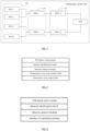
- Fig. 1 is a schematic diagram of a system architecture of a photovoltaic system provided by an embodiment of the present application.
- the photovoltaic system 100 includes smart photovoltaic units 200, photovoltaic convergence boxes 300 and smart protocol convert units 400 used as nodes for networking as well as a center supervise unit 500.
- a plurality of smart photovoltaic units 200 are electrically connected and converged to the photovoltaic convergence boxes 300 and then are connected into the smart protocol convert units 400 to form a grouped sub-system, a plurality of groups of such sub-systems constitute a complete photovoltaic system 100 together with one center supervise unit 500, and thus one grouped sub-system is composed of one photovoltaic convergence box 300, one smart protocol convert unit 400 and at least one smart photovoltaic unit 200.
- a first grouped sub-system includes a smart photovoltaic unit 1, a smart photovoltaic unit 2, a photovoltaic convergence box 1 and a smart protocol convert unit 1
- a second grouped sub-system includes a smart photovoltaic unit 3 to a smart photovoltaic unit N, a photovoltaic convergence box 2 and a smart protocol convert unit 2
- the photovoltaic system 100 is composed of the first grouped sub-system, the second grouped sub-system and the center supervise unit 500.
- the smart photovoltaic units 200, the photovoltaic convergence boxes 300 and the smart protocol convert units 400 are connected with one another through power line communication (PLC), the smart protocol convert units 400 and the center supervise unit 500 are connected with each other through a controller area network (CAN) or a field bus such as RS485, besides, all the smart photovoltaic units 200, photovoltaic convergence boxes 300 and smart protocol convert units 400 realize interaction and management through power line communication, and thus the communication cost is lowered.
- PLC power line communication
- CAN controller area network
- RS485 field bus
- configuration information related to physical layouts further needs to be added for each node, especially the smart photovoltaic units 200, in the photovoltaic system 100, such as a photovoltaic array (where the smart photovoltaic units 200 are located) serial number (PVSN) and a photovoltaic array matrix (PVM) in this array matrix (the photovoltaic array matrix may also be decomposed into two planar coordinate values PVM_X and PVM_Y), selective installation positions of a PCB and an SPCU and other information, all for facilitating the simplicity and visuality of operation and maintenance.
- a photovoltaic array where the smart photovoltaic units 200 are located
- PVSN serial number
- PVM photovoltaic array matrix
- the photovoltaic array matrix may also be decomposed into two planar coordinate values PVM_X and PVM_Y), selective installation positions of a PCB and an SPCU and other information, all for facilitating the simplicity and visuality of operation and maintenance.
- the PVSN is an identification code of a photovoltaic array region
- the PVM is a coordinate position identification of a node in an array and is used to represent which row and which column the node is located in the array.
- configuration table information of each node device is as follows.
- Fig. 2 is a node configuration table for an SPU.
- the node configuration table for the SPU includes layout information such as a DSN, Panld, PanAddr, a PVSN and a PVM of this node.
- Fig. 3 is a node configuration table for a PCB.
- the node configuration table for the PCB includes a DSN, Panld, PanAddr, and selective installation position information of this node.
- the node configuration table for the SPCU includes a DSN, Panld, PanAddr, and selective installation position information of this node.
- the photovoltaic system 100 and application scenarios described in the embodiment of the present application are to illustrate the technical solution of the embodiment of the present application more clearly, and do not constitute a limitation on the technical solution provided by the embodiment of the present application. It is known to those skilled in the art that with the evolution of network topology and the emergence of new application scenarios, the technical solution provided by the embodiment of the present application is also applicable to similar technical problems.
- the photovoltaic system shown in Fig. 1 does not constitute a limitation to the embodiment of the present application, and may include more components or fewer components than those shown in the figure, or some components may be combined, or a different component deployment may be used.
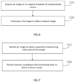
- Fig. 5 is a flow diagram of a data processing method for a photovoltaic system provided by an embodiment of the present application.
- the data processing method for the photovoltaic system includes, but is not limited to, steps S100-S400.
- the photovoltaic system includes a center supervise unit as well as smart photovoltaic units, photovoltaic convergence boxes and smart protocol convert units used as nodes for networking.
- a layout image is acquired, the layout image including a plurality of information entry areas carrying identification information.
- the identification information in the information entry areas is identified, so as to obtain area serial numbers, serial number information and grouping information of the information entry areas.
- the area serial numbers are used to distinguish between node categories in the photovoltaic system
- the serial number information is used to represent serial numbers of nodes
- the grouping information is used to represent a grouping condition of nodes in the photovoltaic system.
- the area serial numbers are photovoltaic array serial numbers.
- the identification information in the information entry areas is identified, so as to obtain the area serial numbers, the serial number information and the grouping information of the information entry areas, and thus an arrangement relationship of nodes in the photovoltaic system can be judged accurately.
- a method of identifying the identification information adopts an image recognition technology, wherein the image recognition technology may be an optical character recognition (OCR) technology or a handwritten character recognition (HCR) technology.
- OCR optical character recognition
- HCR handwritten character recognition
- the photovoltaic coordinate information is a photovoltaic array matrix.
- the grouping information, the area serial numbers, the photovoltaic coordinate information and the serial number information are sent to the center supervise unit in the photovoltaic system, so that the center supervise unit generates a network configuration table according to the grouping information, and distributes, according to the network configuration table, to the smart protocol convert units configuration information corresponding to the smart photovoltaic units, the photovoltaic convergence boxes and the smart protocol convert units.
- serial numbers of the smart photovoltaic units, serial numbers of the photovoltaic convergence boxes and serial numbers of the smart protocol convert units in the present embodiment are device serial numbers (DSNs) of respective nodes.
- the grouping information, the area serial numbers, the photovoltaic coordinate information and the serial number information are sent to the center supervise unit, so that the center supervise unit generates the network configuration table according to the grouping information, and distributes to the smart protocol convert units the configuration information corresponding to the smart photovoltaic units, the photovoltaic convergence boxes and the smart protocol convert units through a CAN bus, and thus the nodes in the photovoltaic system are synchronously configured.
- the center supervise unit distributes the network configuration table to the smart protocol convert units through the CAN bus first, and then the smart protocol convert units are used to distribute the configuration information corresponding to all the nodes through PLC network broadcasting, so as to achieve synchronous configuration from top to bottom.
- Fig. 6 is illustration for step S100 in Fig. 5 , and step S100 includes, but is not limited to, step S110 to step S120.
- the original template is provided with a plurality of meshes according to a preset row-column relationship, and the area serial numbers, the serial number information and the grouping information are entered into the meshes to form the information entry areas.
- the image of the original template of the photovoltaic system is acquired first, then the image is preprocessed, so as to obtain the layout image corresponding to the original template, and a precise mapping relationship between respective nodes and logic configurations in the photovoltaic system is achieved.
- the original template of the photovoltaic system may be a photo or drawing paper or the like of the photovoltaic system, and the dimension of the photo or drawing paper may be 297 mm ⁇ 420 mm or 210 mm ⁇ 297 mm, which is convenient for classified entry of node information and convenient for subsequent scanning recognition and configuration generation.
- the serial number information in the meshes may be directly input by handwriting, or pasted on a device of the photovoltaic system by using a barcode or QR code label, and thus the difficulty and the error rate of information entry are lowered.
- the area serial numbers in the meshes may be printed digital labels which are pasted or directly input by handwriting.
- a correct value must be input into nodes of the smart photovoltaic units, a default value is 1, 0 is input into nodes of the photovoltaic convergence boxes consistently, while for nodes of the smart protocol convert units, the area codes are kept blank and forbidden from inputting, and when it is required to enter different node information into the same template due to the lack of site templates, node categories may be distinguished through the area serial numbers, and thus the mixing of the node information is avoided.
- the grouping information in the meshes may be printed digital labels which are pasted or directly handwritten, and SPUs, PCBs and SPCUs which are electrically connected in the same group have the same group number, so that respective nodes in the photovoltaic system are precisely grouped.
- Fig. 7 is illustration for step S120 in Fig. 6 , and step S120 includes, but is not limited to, step S121 to step S122.
- the image is identified to obtain a plurality of positioning holes around the image.
- the quantity of the positioning holes may be 4, 5 or 6, in the present embodiment, the quantity of the positioning holes is 4, and the 4 positioning holes are arranged at vertices of four corners of the image evenly.
- the meshes are positioned according to the positioning holes to obtain the layout image.
- the image is identified to obtain the plurality of positioning holes around the image
- the meshes are positioned according to the positioning holes to determine whether the meshes are complete or not, so as to obtain the layout image, and the situations of missing and the like of the layout image are avoided.
- the image is identified by taking photos of images of the entered information for identification, in the process of taking photos for identification, image contents and the positioning holes must be clear and visible, and thus the meshes are positioned, and the complete layout image is obtained.
- the preset row-column relationship includes M rows and N columns into which the layout image is divided in a region defined by the positioning holes, and thus the beauty and cleanliness of the layout image are improved, the respective meshes have an equal area, and the information is completely entered.
- the preset row-column relationship may include 5 rows and 6 columns, 4 rows and 5 columns, or 6 rows and 8 columns or the like into which the layout image is divided, which is not specifically limited in the present embodiment.
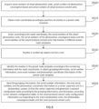
- FIG. 8 is a flow diagram of a data processing method for a photovoltaic system provided by another embodiment of the present application.
- a data processing method for the photovoltaic system includes, but is not limited to, steps S500-S550.
- the photovoltaic system includes a center supervise unit as well as smart photovoltaic units, photovoltaic convergence boxes and smart protocol convert units used as nodes for networking.
- serial numbers of the smart photovoltaic units, the serial numbers of the photovoltaic convergence boxes and the serial numbers of the smart protocol convert units in the present embodiment are device serial numbers of respective nodes.
- mesh coordinates are obtained according to positions of meshes in a preset node template.
- the serial numbers of the smart photovoltaic units, the serial numbers of the photovoltaic convergence boxes and the serial numbers of the smart protocol convert units are entered into meshes in different preset node templates.
- the numbering request is used to number meshes in the preset node template after entering to obtain numbering information.
- the meshes in the preset node template are identified according to the numbering information and the mesh coordinates, to obtain grouping information, serial number information, area serial numbers and photovoltaic coordinate information of the preset node template.
- the grouping information is used to represent a grouping condition of nodes in the photovoltaic system.
- the grouping information, the serial number information, the area serial numbers and the photovoltaic coordinate information are sent to the center supervise unit in the photovoltaic system, so that the center supervise unit generates a network configuration table according to the grouping information, and distributes, according to the network configuration table, to the smart protocol convert units configuration information corresponding to the smart photovoltaic units, the photovoltaic convergence boxes and the smart protocol convert units.
- the serial numbers of the smart photovoltaic units, the serial numbers of the photovoltaic convergence boxes and the serial numbers of the smart protocol convert units are acquired first, and the mesh coordinates are obtained according to the positions of the meshes in the preset node template, which is convenient for entry of information of respective nodes of the smart photovoltaic units.
- the serial numbers of the smart photovoltaic units, the serial numbers of the photovoltaic convergence boxes and the serial numbers of the smart protocol convert units are entered into meshes in different preset node templates according to the mesh coordinates, a precise mapping relationship between physical objects and logic configurations is established, respective nodes in different photovoltaic systems correspond to different preset node templates, and different node information is entered accurately.
- the numbering request sent by the user is received, the meshes in the preset node template are identified according to the numbering information and the mesh coordinates, to obtain the grouping information, the serial number information, the area serial numbers and the photovoltaic coordinate information of the preset node template, and respective nodes in the photovoltaic system are grouped.
- the grouping information, the serial number information, the area serial numbers and the photovoltaic coordinate information are sent to the center supervise unit in the photovoltaic system, so that the center supervise unit generates the network configuration table according to the grouping information, and distributes, according to the network configuration table, to the smart protocol convert units the configuration information corresponding to the smart photovoltaic units, the photovoltaic convergence boxes and the smart protocol convert units, which is convenient for the center supervise unit to manage the photovoltaic system.
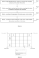
- Fig. 9 is illustration for step S510 in Fig. 8 , and step S510 includes, but is not limited to, step S511 to step S513.
- the preset node template includes a photovoltaic unit template, a photovoltaic convergence template and a protocol convert template
- the mesh coordinates include photovoltaic mesh coordinates, convergence mesh coordinates and protocol mesh coordinates.
- the photovoltaic mesh coordinates are obtained according to positions of meshes in the photovoltaic unit template.
- the convergence mesh coordinates are obtained according to positions of meshes in the photovoltaic convergence template.
- the protocol mesh coordinates are obtained according to positions of meshes in the protocol convert template.
- the different photovoltaic mesh coordinates, convergence mesh coordinates and protocol mesh coordinates are obtained according to the positions of the meshes in the photovoltaic unit template, the positions of the meshes in the photovoltaic convergence template and the positions of the meshes in the protocol convert template, and thus node relationships in the photovoltaic system are arranged accurately.
- M and N may be defined randomly according to actual situations, extension after defining is also supported, and it is guaranteed that any scale of SPU networking can be satisfied.
- Fig. 10 is illustration for step S520 in Fig. 8 , and step S520 includes, but is not limited to, step S521 to step S523.
- the serial numbers of the smart photovoltaic units, the serial numbers of the photovoltaic convergence boxes and the serial numbers of the smart protocol convert units are entered into the meshes in the corresponding photovoltaic unit template, the meshes in the corresponding photovoltaic convergence template and the meshes in the corresponding protocol convert template respectively according to the photovoltaic mesh coordinates, the convergence mesh coordinates and the protocol mesh coordinates, and thus different node information is entered, which facilitates viewing and management.
- the serial numbers of the photovoltaic convergence boxes are sequentially entered into the meshes in the photovoltaic convergence template, for example, assuming that the template has M*N meshes, it represents that entry of M*N photovoltaic convergence box nodes may be supported, and similarly, the serial numbers of the smart protocol convert units are also entered into the meshes in the protocol convert template in accordance with the same way as the photovoltaic convergence boxes.
- Fig. 11 is illustration for step S540 in Fig. 8 , and step S540 includes, but is not limited to, step S541 to step S544.
- image identification is performed on the meshes in the photovoltaic unit template, the meshes in the photovoltaic convergence template and the meshes in the protocol convert template in the preset node template, so as to obtain the serial number information of the photovoltaic unit template, the serial number information of the photovoltaic convergence template and the serial number information of the protocol convert template.
- the meshes in the preset node template are grouped according to the numbering information obtained from the numbering request of the user, and thus the grouping information of the respective meshes is obtained, which facilitates subsequent sending of the grouping information to the center supervise unit.
- the area serial numbers are used to represent a correspondence relationship between the meshes in the preset node template and the smart photovoltaic units.
- the photovoltaic coordinate information is used to represent a correspondence relationship between the photovoltaic mesh coordinates and the mesh coordinates.
- the grouping information, the area serial numbers, the photovoltaic coordinate information and the serial number information are sent to the center supervise unit, so that the center supervise unit generates the network configuration table according to the grouping information, and distributes to the smart protocol convert units the configuration information corresponding to the smart photovoltaic units, the photovoltaic convergence boxes and the smart protocol convert units through a CAN bus, and thus the nodes in the photovoltaic system are synchronously configured.
- the center supervise unit distributes the network configuration table to the smart protocol convert units through a CAN bus first, and then the smart protocol convert units are used to distribute the configuration information corresponding to all the nodes through PLC network broadcasting, so as to achieve synchronous configuration from top to bottom.
- Fig. 12 is a schematic diagram of a layout image provided by an example of the present application.
- Example I demonstrates an information entry process of a photovoltaic system, and the information entry process is as following steps 1 to 5:
- the layout images are suitable for a scenario where a system capacity is not very large, operations are simple and visual, technical requirements for engineering opening personnel are lower, and the labor cost for opening is also lower.
- Fig. 13 is a schematic diagram of a preset node template provided by another example of the present application.
- Example I To achieve safe, simple, rapid and accurate network configuration, first, the design method as shown in Example I is required, which is omitted here.
- Example II demonstrates a process of another information entry method of a photovoltaic system, and the information entry process is as following steps 1 to 5:
- the preset node template supports a system application scenario with a super-large capacity, and physical objects such as a physical layout template and adhesive labels special for opening of each device are not needed, which is environmentally friendlier; and the deficiency is that engineering opening personnel shall be able to accurately operate opening configuration APP software, and the technical requirement is a little bit higher.
- Example I To achieve safe, simple, rapid and accurate network configuration, first, the design method as shown in Example I is required, which is omitted here.
- Example III is a network configuration process for the layout image in the present application, and has the following steps 1 to 8:
- Example I To achieve safe, simple, rapid and accurate network configuration, first, the design method as shown in Example I is required, which is omitted here.
- Example IV is a network configuration process for the preset node template in the present application, and has the following steps 1 to 6:
- Example I to Example IV require, when completing information entry, the entry of DSNs of SPU devices, SPCU devices and PCB devices for subsequent networking, and district division is performed manually to guarantee that devices in the same district have the same Panld. Such methods have no requirement for the value of Panld itself, and are relatively flexible, but it is also somewhat cumbersome.
- Example V adopts SPCU devices and PCB devices with a slot recognition function, a PLC network configuration process is simplified, and the station opening efficiency can be effectively improved.
- the slot recognition technology can guarantee the consistency between physical slots of SPCUs and PCBs and subsequent communication addresses, thereby guaranteeing the uniqueness when slot numbers are directly used as Panld and the consistency of networking Panld of SPUs connected thereto.
- Example V is a network configuration process for the preset node template in the present application, and has the following steps 1 to 6:
- the CSU reminds that there are node devices which are missed and not entered through audible and visual alarms, opening personnel verify by referring to the templates, and supplement information entry, so as to ensure the correct and complete configuration.
- the data processing terminal 2000 includes a memory 210, a processor 220 and a computer program stored on the memory 210 and capable of running on the processor 220.
- the processor 220 and the memory 210 may be connected through a bus or other means.
- the memory 210 may be configured to store non-transitory software programs and non-transitory computer-executable programs.
- the memory 210 may include a high-speed random access memory, and may also include a non-transitory memory, such as at least one disk storage device, a flash memory device, or other non-transitory solid-state storage devices.
- the memory 210 may include a memory which is remotely disposed relative to the processor 220, and the remote memory may be connected to the processor 220 through a network. Instances of the above network include but are not limited to the Internet, the Intranet, a local area network, a mobile communication network and a combination thereof.
- the embodiments described above are merely illustrative.
- the units described as separate components may or may not be physically separated, that is, they may be located in one place, or distributed to multiple network units. Some or all of the modules may be selected according to actual needs to achieve the objectives of the solutions of the embodiments.
- an embodiment of the present application further provides a computer-readable storage medium, storing computer-executable instructions.
- the computer-executable instructions are executed by one center supervise unit or controller, such as one center supervise unit in the above device embodiments, so that the above center supervise unit is enabled to execute the data processing method for the photovoltaic system in the above embodiments.
- an embodiment of the present application further provides a computer program product, including computer programs or computer instructions which are stored in a computer-readable storage medium.
- a center supervise unit of a computer device reads the computer programs or the computer instructions from the computer-readable storage medium, and the center supervise unit executes the computer programs or the computer instructions, such that the computer device executes the data processing method for the photovoltaic system in any aforementioned embodiment.
- the data processing method for the photovoltaic system at least has the following beneficial effects: a layout image including a plurality of information entry areas is acquired, identification information carried in the information entry areas and a position relationship of the information entry areas are identified to obtain area serial numbers, serial number information, grouping information and photovoltaic coordinate information of the information entry areas, and thus node categories in the photovoltaic system can be distinguished according to the area serial numbers, a grouping condition of nodes in the photovoltaic system is obtained according to the grouping information, and device information and the position relationship in the photovoltaic system are obtained.
- the grouping information, the area serial numbers, the photovoltaic coordinate information and the serial number information are sent to a center supervise unit, so that the center supervise unit can generate a network configuration table according to the grouping information, and distribute, according to the network configuration table, to smart protocol convert units configuration information corresponding to smart photovoltaic units, photovoltaic convergence boxes and the smart protocol convert units.
- the photovoltaic system is managed by the center supervise unit, and the management efficiency for the photovoltaic system is improved.
- a center supervise unit such as a central center supervise unit, a digital signal center supervise unit, or a micro-center supervise unit, or as hardware, or as an integrated circuit, such as an application-specific integrated circuit.
- Such software may be distributed on a computer-readable medium, which may include a computer storage medium (or non-temporary medium) and a communication medium (or temporary medium).
- the term computer storage medium includes volatile and non-volatile, and removable and non-removable media implemented in any method or technology for storing information, such as computer-readable instructions, data structures, program modules, or other data.
- the computer storage medium includes, but is not limited to, a RAM, a ROM, an EEPROM, a flash memory or other memory techniques, a CD-ROM, a digital versatile disc (DVD) or other optical disk storage, a magnetic cassette, a magnetic tape, magnetic disk storage or other magnetic storage apparatuses, or any other media that can be used to store desired information and can be accessed by a computer.
- a communication medium typically includes computer-readable instructions, data structures, program modules, or other data in modulated data signals such as carriers or other transmission mechanisms, and may include any information delivery medium.
Landscapes
- Engineering & Computer Science (AREA)
- Physics & Mathematics (AREA)
- Computer Vision & Pattern Recognition (AREA)
- Theoretical Computer Science (AREA)
- General Physics & Mathematics (AREA)
- Computer Networks & Wireless Communication (AREA)
- Artificial Intelligence (AREA)
- Multimedia (AREA)
- Signal Processing (AREA)
- Health & Medical Sciences (AREA)
- General Health & Medical Sciences (AREA)
- Electromagnetism (AREA)
- Toxicology (AREA)
- Computer Security & Cryptography (AREA)
- Computing Systems (AREA)
- Medical Informatics (AREA)
- Management, Administration, Business Operations System, And Electronic Commerce (AREA)
- Power Sources (AREA)
Applications Claiming Priority (2)
| Application Number | Priority Date | Filing Date | Title |
|---|---|---|---|
| CN202210705278.3A CN116264009B (zh) | 2022-06-21 | 2022-06-21 | 光伏系统的数据处理方法、数据处理终端及存储介质 |
| PCT/CN2023/100790 WO2023246657A1 (zh) | 2022-06-21 | 2023-06-16 | 光伏系统的数据处理方法、数据处理终端及存储介质 |
Publications (2)
| Publication Number | Publication Date |
|---|---|
| EP4546293A1 true EP4546293A1 (de) | 2025-04-30 |
| EP4546293A4 EP4546293A4 (de) | 2025-10-22 |
Family
ID=86722808
Family Applications (1)
| Application Number | Title | Priority Date | Filing Date |
|---|---|---|---|
| EP23826306.5A Pending EP4546293A4 (de) | 2022-06-21 | 2023-06-16 | Datenverarbeitungsverfahren für fotovoltaisches system, datenverarbeitungsendgerät und speichermedium |
Country Status (3)
| Country | Link |
|---|---|
| EP (1) | EP4546293A4 (de) |
| CN (1) | CN116264009B (de) |
| WO (1) | WO2023246657A1 (de) |
Families Citing this family (4)
| Publication number | Priority date | Publication date | Assignee | Title |
|---|---|---|---|---|
| CN117195320B (zh) * | 2023-09-11 | 2024-04-05 | 重庆千信新能源有限公司 | 通过大数据图像生成光伏组件能源数据的安全方法 |
| CN119862615A (zh) * | 2023-10-19 | 2025-04-22 | 杭州禾迈电力电子股份有限公司 | 光伏发电系统的布局图生成方法、装置、系统及存储介质 |
| CN119814522B (zh) * | 2024-12-18 | 2025-12-05 | 国网电力科学研究院有限公司 | 一种分布式光伏通信网多协议应用层组网方法、系统、设备及存储介质 |
| CN119963687B (zh) * | 2025-04-10 | 2025-08-05 | 上海思格源智能科技有限公司 | 光伏系统的图像生成方法、装置、光伏系统、电子设备、存储介质和计算机程序产品 |
Family Cites Families (10)
| Publication number | Priority date | Publication date | Assignee | Title |
|---|---|---|---|---|
| US20120158200A1 (en) * | 2010-12-17 | 2012-06-21 | Greenvolts, Inc | Integrated performance monitoring for a concentrated photovoltaic (cpv) system |
| US9270842B2 (en) * | 2011-12-20 | 2016-02-23 | Ricoh Company, Ltd. | Additional input sources for data acquisition at distributed scan management systems |
| US9589079B2 (en) * | 2014-11-17 | 2017-03-07 | Sunedison, Inc. | Methods and systems for designing photovoltaic systems |
| KR102610440B1 (ko) * | 2016-08-08 | 2023-12-06 | 상라오 징코 솔라 테크놀러지 디벨롭먼트 컴퍼니, 리미티드 | 태양광 모듈, 및 이를 구비하는 태양광 시스템 |
| CN111385275A (zh) * | 2018-12-30 | 2020-07-07 | 国家能源投资集团有限责任公司 | 光伏系统中数据的处理方法、装置、存储介质和处理器 |
| CN115424286A (zh) * | 2019-03-04 | 2022-12-02 | 华为数字能源技术有限公司 | 光伏系统及光伏阵列的电子布局图获取方法 |
| CN110472941B (zh) * | 2019-08-12 | 2022-08-09 | Oppo(重庆)智能科技有限公司 | 基于通知消息的日程创建方法和装置、终端、存储介质 |
| CN112288131B (zh) * | 2020-09-24 | 2021-06-11 | 和智信(山东)大数据科技有限公司 | 公交站点优化方法、电子设备及计算机可读存储介质 |
| CN113703785B (zh) * | 2021-08-31 | 2023-10-31 | 康键信息技术(深圳)有限公司 | 基于组件的平台部署方法、装置、设备及存储介质 |
| CN113946592B (zh) * | 2021-12-21 | 2022-03-22 | 湖南天云软件技术有限公司 | 配置管理数据库更新方法、装置、设备、介质及程序产品 |
-
2022
- 2022-06-21 CN CN202210705278.3A patent/CN116264009B/zh active Active
-
2023
- 2023-06-16 WO PCT/CN2023/100790 patent/WO2023246657A1/zh not_active Ceased
- 2023-06-16 EP EP23826306.5A patent/EP4546293A4/de active Pending
Also Published As
| Publication number | Publication date |
|---|---|
| WO2023246657A1 (zh) | 2023-12-28 |
| CN116264009B (zh) | 2023-10-27 |
| CN116264009A (zh) | 2023-06-16 |
| EP4546293A4 (de) | 2025-10-22 |
Similar Documents
| Publication | Publication Date | Title |
|---|---|---|
| CN116264009B (zh) | 光伏系统的数据处理方法、数据处理终端及存储介质 | |
| US11799418B2 (en) | Method, apparatus, and system for obtaining electronic layout applied to photovoltaic array | |
| CN107292003A (zh) | 一种电网厂站接线图自动生成方法 | |
| CN108388620B (zh) | 一种土地审批测绘数据处理信息系统 | |
| CN109240626A (zh) | 标签打印方法及系统 | |
| CN106202447A (zh) | 一种具备生产与管理一体化的数字地图制图系统 | |
| CN103036742A (zh) | 通信设备批量检测的控制方法及系统 | |
| CN113342907B (zh) | 一种用能信息采集系统台区拓扑画像绘制方法与系统 | |
| CN116991998A (zh) | 一种基于ai语言应答模型的电力仿真培训方法、系统 | |
| CN106227689A (zh) | 一种基于物联网及云技术的数据采集终端 | |
| CN112990560B (zh) | 一种电网地理接线图自动生成方法及装置 | |
| CN111125227A (zh) | 交互式电子手册数据处理方法、装置、存储介质及设备 | |
| CN110058879A (zh) | 一种智能终端快速组态方法 | |
| CN108734775A (zh) | 一种低成本的道路资产自动化快速建模方法及系统 | |
| CN104731992B (zh) | 配电自动化建模方法及装置 | |
| CN117472922A (zh) | 一种电网设备资产的图数模一致性校验方法、系统及终端 | |
| CN117632068A (zh) | 配屏方法、装置、控制系统、显示设备及可读存储介质 | |
| CN111290904A (zh) | 显示屏调试方法、装置、系统和计算机可读介质 | |
| CN111539430B (zh) | 一种模拟电表的识别装置及识别方法 | |
| CN114139876A (zh) | 基于大数据的电力工程图纸资料自动管理方法 | |
| CN105046345A (zh) | 一种快速创建电网厂站图的方法 | |
| CN218446685U (zh) | 一种抽水蓄能电站检修作业远程定位监理及验收装置 | |
| CN116167350B (zh) | 基于可配置模板的自定义导出装置、方法、设备及介质 | |
| CN113485416B (zh) | 一种电网安全检测方法 | |
| WO2025192797A1 (ko) | 태양광 모듈의 mlpe 디바이스를 자동으로 매핑하는 방법 및 장치 |
Legal Events
| Date | Code | Title | Description |
|---|---|---|---|
| STAA | Information on the status of an ep patent application or granted ep patent |
Free format text: STATUS: THE INTERNATIONAL PUBLICATION HAS BEEN MADE |
|
| PUAI | Public reference made under article 153(3) epc to a published international application that has entered the european phase |
Free format text: ORIGINAL CODE: 0009012 |
|
| STAA | Information on the status of an ep patent application or granted ep patent |
Free format text: STATUS: REQUEST FOR EXAMINATION WAS MADE |
|
| 17P | Request for examination filed |
Effective date: 20250115 |
|
| AK | Designated contracting states |
Kind code of ref document: A1 Designated state(s): AL AT BE BG CH CY CZ DE DK EE ES FI FR GB GR HR HU IE IS IT LI LT LU LV MC ME MK MT NL NO PL PT RO RS SE SI SK SM TR |
|
| DAV | Request for validation of the european patent (deleted) | ||
| DAX | Request for extension of the european patent (deleted) | ||
| A4 | Supplementary search report drawn up and despatched |
Effective date: 20250923 |
|
| RIC1 | Information provided on ipc code assigned before grant |
Ipc: G06V 30/18 20220101AFI20250917BHEP Ipc: H04L 41/0853 20220101ALI20250917BHEP Ipc: H04L 67/12 20220101ALI20250917BHEP Ipc: H04L 69/08 20220101ALI20250917BHEP Ipc: G06K 7/14 20060101ALI20250917BHEP Ipc: G06V 30/422 20220101ALI20250917BHEP |