EP4546372A1 - Dispositif d'entraînement pour couvercle supérieur incurvé, vérificateur de positionnement et procédé de positionnement et de détection - Google Patents
Dispositif d'entraînement pour couvercle supérieur incurvé, vérificateur de positionnement et procédé de positionnement et de détection Download PDFInfo
- Publication number
- EP4546372A1 EP4546372A1 EP23929413.5A EP23929413A EP4546372A1 EP 4546372 A1 EP4546372 A1 EP 4546372A1 EP 23929413 A EP23929413 A EP 23929413A EP 4546372 A1 EP4546372 A1 EP 4546372A1
- Authority
- EP
- European Patent Office
- Prior art keywords
- driving
- pressure vessel
- reactor pressure
- probe
- chain
- Prior art date
- Legal status (The legal status is an assumption and is not a legal conclusion. Google has not performed a legal analysis and makes no representation as to the accuracy of the status listed.)
- Pending
Links
Images


Classifications
-
- G—PHYSICS
- G21—NUCLEAR PHYSICS; NUCLEAR ENGINEERING
- G21C—NUCLEAR REACTORS
- G21C17/00—Monitoring; Testing ; Maintaining
- G21C17/003—Remote inspection of vessels, e.g. pressure vessels
- G21C17/007—Inspection of the outer surfaces of vessels
-
- Y—GENERAL TAGGING OF NEW TECHNOLOGICAL DEVELOPMENTS; GENERAL TAGGING OF CROSS-SECTIONAL TECHNOLOGIES SPANNING OVER SEVERAL SECTIONS OF THE IPC; TECHNICAL SUBJECTS COVERED BY FORMER USPC CROSS-REFERENCE ART COLLECTIONS [XRACs] AND DIGESTS
- Y02—TECHNOLOGIES OR APPLICATIONS FOR MITIGATION OR ADAPTATION AGAINST CLIMATE CHANGE
- Y02E—REDUCTION OF GREENHOUSE GAS [GHG] EMISSIONS, RELATED TO ENERGY GENERATION, TRANSMISSION OR DISTRIBUTION
- Y02E30/00—Energy generation of nuclear origin
- Y02E30/30—Nuclear fission reactors
Definitions
- the invention belongs to the field of nuclear power inspection equipment and particularly relates to a driving device, a positioning and inspection mechanism, and a positioning and inspection method for a curved reactor pressure vessel head.
- the reactor pressure vessel reactor pressure vessel head in a nuclear power plant is the core equipment of a nuclear reactor. To ensure the safe operation of nuclear power plants, it is necessary to carry out surface and volume nondestructive testing on the base material of the reactor pressure vessel head regularly. Because the reactor pressure vessel head is spherical and blocked by CRDM penetrations and instrumentation penetrations, several belt-shaped areas to be inspected are formed. At present, no device can accurately position and move the probe along the belt-shaped area on the premise of keeping the probe adhered to the reactor pressure vessel head.
- the object of the present invention is to provide that can make the probe move along a belt-shaped area on the premise of keeping the height of the probe and the reactor pressure vessel head constant, and the projection of the moving track on the bottom surface of the reactor pressure vessel head is a straight line.
- a driving device for a curved reactor pressure vessel head the reactor pressure vessel head comprises a first bottom surface and a curved top surface located on the first bottom surface, wherein the top surface is provided with a plurality of inspection channels, and the projection of the inspection channels on the first bottom surface extends along a straight line, wherin the driving device comprises:
- the invention also provides a driving device for a curved reactor pressure vessel head, the reactor pressure vessel head comprises a first bottom surface and a curved top surface located on the first bottom surface, wherein the top surface is provided with a plurality of inspection channels, and the projection of the inspection channels on the first bottom surface extends along a straight line, and wherein the driving device comprises:
- the driving assembly comprises a magnetic wheel rotatably connected to the driving frame and a first driving motor for driving the magnetic wheel to rotate, and the magnetic wheel can always make the driving mechanism adsorbed on the reactor pressure vessel head.
- the dimension of the driving frame in the left-right direction is its width
- the dimension of the chain in the left-right direction is its width
- the widths of the driving frame and the chain are not greater than the width of the inspection channel so that the driving frame is limited by the first channel and the second channel to further ensure that it moves along the length direction of the inspection channel.
- the widths of the driving frame and the chain are both 0.5-2mm smaller than the width of the inspection channel, and to reduce the processing difficulty, the widths of the driving frame and the chain can be slightly smaller than the width of the inspection channel.
- the chain comprises a plurality of chain plates that are connected in turn, pin shafts that pass through two adjacent chain plates, and connecting pieces that are used for connecting the front and rear adjacent pin shafts, the front and rear ends of the connecting pieces are respectively connected with the same side ends of the adjacent pin shafts in rotation, and the connecting pieces can further ensure that the chain does not bend in the left-right direction.
- two ends of the pin shaft are rotatably connected with rollers to prevent the chain plate from wearing the reactor pressure vessel head, and the rollers are located between the chain plate and the connecting piece on the same side thereof.
- a connecting groove and a connecting head are formed on the chain plate, the connecting head of the chain plate is located in the connecting groove of the chain plate at the front side thereof, and the pin shaft passes through the connecting head of the chain plate and the chain plate at the front side to rotationally connect the chain plate and the chain plate at the front side; and the cooperation of the connecting groove and the connecting head can further ensure that the chain does not bend in the left-right direction.
- an accommodating groove penetrating along the length direction of the chain is formed on the chain plate above the connecting groove, which not only reduces the overall weight of the chain, but also can receive the cables of the driving device, the positioning mechanism, and the inspection mechanism, making wiring easier, and at the same time, due to the limitation of the bending angle of the chain plate, the cable can be prevented from being excessively bent to cause damage.
- the wedge assembly comprises a wedge fixed at the bottom of the driving frame, a supporting foot installed below the wedge and always having a movement tendency to protrude away from the direction of the driving frame, and an elastic member installed between the supporting foot and the wedge to make the supporting foot always have a movement tendency to protrude away from the driving frame.
- the telescopic design of the supporting foot ensures that the driving frame always remains parallel to the first bottom surface.
- the supporting feet are respectively arranged on the wedge and located on the left and right sides of the lower end face of the wedge, and the maximum height difference that the supporting feet on the left and right sides can reach after the respective expansion and contraction is not less than the height difference of the upper end face of the reactor pressure vessel head in the width direction of each inspection channel, which can meet the height difference of the upper end face of the reactor pressure vessel head in all inspection channels.
- each wedge is an arc surface
- the arc surface of each wedge is respectively matched with the upper end face of the reactor pressure vessel head in an inspection channel.
- An inspection mechanism for inspecting the reactor pressure vessel head and the defects of components on the reactor pressure vessel head which comprises a probe mounted on the rear end of the driving mechanism for inspection, and the probe can move in a direction perpendicular to the movement of the driving frame on a plane parallel to the first bottom surface, and the driving device can effectively and accurately complete the inspection of the reactor pressure vessel head in cooperation with the inspection mechanism and the positioning mechanism.
- the inspection mechanism comprises an adjusting assembly for driving the probe to adjust the position
- the adjusting assembly comprises first side plates fixed on the left and right sides of the driving frame, a first slide rail arranged between the first side plates in the left-right direction, a first mounting housing slidably connected to the first slide rail, a second driving motor fixed in the first mounting housing and with an output shaft extending from the first mounting housing and a probe frame, a driving gear mounted on the second driving motor, a rack mounted on the driving frame and meshed with the driving gear, the probe is mounted on the probe frame, and the rack is located below the gear and arranged in the left-right direction.
- the second driving motor rotates to drive the gear to roll on the rack so that the first mounting housing moves on the first slide rail and finally drives the probe frame to move left and right. Therefore, the probe frame can move in the first direction and the second direction, and the reactor pressure vessel head can be fully inspected.
- the probe frame comprises a first supporting arm fixed on the first mounting housing and partially extending out of the driving frame, at least two second sliders fixed on the first supporting arm and symmetrically arranged with each other, second sliding rails respectively connected to the second sliders in a sliding way, and a telescopic member fixed on the first supporting arm and connected with the probe, and the telescopic member moves the probe and second sliding rails on a second slider, to ensure that the probe always adheres to the surface of the reactor pressure vessel head.
- the positioning and inspection mechanism comprises a limit assembly, which comprises pressing pieces installed on the driving frame and located on the left and right sides of the first mounting housing, a trigger fixed on the first mounting housing, a limit switch fixed on the driving frame by the pressing pieces.
- a limit assembly which comprises pressing pieces installed on the driving frame and located on the left and right sides of the first mounting housing, a trigger fixed on the first mounting housing, a limit switch fixed on the driving frame by the pressing pieces.
- the second driving motor stops working and the first mounting housing reaches the right limit position, which can effectively prevent the first mounting housing from moving excessively and causing damage to all components.
- the probe comprises a probe body, a first probe mounting frame fixed between the second sliding rails, and a second probe mounting frame rotatably connected to the first probe mounting frame, wherein the rotating shaft of the second probe mounting frame on the first probe mounting frame extends in the front-back direction, and the probe body is rotatably connected to the second probe mounting frame, the rotating shaft of the probe body on the second probe mounting frame extends in the left-right direction.
- the two rotating axes are perpendicular to each other, so that the probe body can adapt to the change of the arc shape of the upper end face of the reactor pressure vessel head independently, and the telescopic member can further ensure that the probe body always adheres to the surface of the reactor pressure vessel head.
- the invention also provides a positioning method for a positioning and inspection mechanism for a curved reactor pressure vessel head, wherein the projection of the penetrations of the reactor pressure vessel head on a first bottom surface can be divided into a plurality of groups along a first direction and also can be divided into a plurality of groups along a second direction, a first channel is formed between two adjacent groups of penetrating distributed along the first direction, and a second channel is formed between two adjacent groups of penetrating distributed along the second direction, and the inspection channel comprises the first channel and the second channel, and the first direction and the second direction intersect and both parallel to the first bottom surface.
- the positioning and inspection mechanism is the positioning and inspection mechanism described above, and the positioning method comprises the following steps:
- the invention also provides a inspection method based on the positioning method described above, which comprises the following steps:
- the invention has the beneficial effects that the position calibration in the first channel and the second channel of the probe can be quickly realized through the vertical arrangement of the plane where the motion track is when the laser emitter and the chain extend out, combined with the characteristic that the bending direction of the chain is limited, and the projection of the motion track of the driving mechanism on the bottom surface of the reactor pressure vessel head extends along a straight line to ensure that it moves along the inspection channel, and the probe can always adhere to the reactor pressure vessel head while moving along the inspection channel, so that the realization mode is simple and effective; realizing accurate positioning of the inspection equipment under the complex arc surface environment of the reactor pressure vessel head surface; because the calibrated position reference objects are unified, the inspection can be reproduced based on the same reference standard, and the defect position of the object to be detected and its defects can be accurately and quickly positioned again.
- the pressure vessel reactor pressure vessel head 0 includes a first bottom surface 02 and a curved top surface 01 located on the first bottom surface 02.
- the top surface 01 has a plurality of inspection channels, and the projection of the inspection channels on the first bottom surface 02 extends along a straight line.
- the projection of penetration 03 on the reactor pressure vessel head on the first bottom surface can be divided into groups along the first direction and also can be divided into groups along the second direction.
- a first channel Q is formed between two adjacent groups of penetrations distributed along the first direction
- a second channel P is formed between two adjacent groups of penetration distributed along the second direction.
- the inspection channel includes the first channel Q and the second channel P, the first direction and second direction intersect and are parallel to the first bottom surface 02. In this embodiment, the first direction and second direction are perpendicular.
- the positioning and inspection mechanism includes a driving device 1, a positioning mechanism 2, an inspection mechanism 3, and a limit assembly 4.
- the driving device 1 includes a driving mechanism 11 and a flexible guiding mechanism 12.
- the driving mechanism 11 comprises a driving frame 111 and a driving assembly 112 mounted on the driving frame 111, wherein the bottom of the driving frame 111 is provided with a wedge assembly for keeping the driving frame in a parallel state with the first bottom surface on the reactor pressure vessel head;
- the driving assembly 112 includes a magnetic wheel 1121 rotatably connected to the driving frame 111, and a first driving motor 1122 that drives the magnetic wheel 1121 to rotate through a pulley assembly 1123. As shown in FIGS.
- the wedge assembly 113 includes a wedge 1131 fixed at the bottom of the driving frame 111, a supporting foot 1132 installed below the wedge 1131 and always having a movement tendency to protrude away from the driving frame 111, an elastic member 1133 installed between the supporting foot 1132 and the wedge 1131 so that the supporting foot 1132 always has a movement tendency to protrude away from the driving frame 111.
- the flexible guiding mechanism 12 is fixedly connected to the front end of the driving frame 111, and the direction parallel to the upper end face of the driving frame 111 and perpendicular to the front-back direction is the left-right direction.
- the lower end face of the wedge block 1131 is provided with a telescopic cavity 1134 with a big belly and a small mouth to accommodate the supporting feet 1132, the upper end of the supporting foot 1132 is thick and completely located in the larger part of the telescopic cavity 1134, and the lower end of the supporting foot extends out of the telescopic cavity 1134.
- the elastic member 1133 causes the supporting feet 1132 to tend to move outward toward the telescoping cavity 1134.
- the supporting feet 1132 are arranged on the wedges 1131 respectively and located on the left and right sides of the lower end faces of the wedges 1131.
- the maximum height difference that the supporting feet 1132 on the left and right sides can reach after respective expansion and contraction is not less than the height difference of the upper end faces of the reactor pressure vessel heads in the width direction of each inspection channel.
- the lower end faces of each wedge 1131 are arc surfaces, and the arc surfaces of each wedge 1131 are respectively matched with an upper end face of the reactor pressure vessel heads in one inspection channel, the inspection channels with identical arc surfaces may share a single wedge 1131, with the supporting foot uncompressed in FIG. 4 .
- FIG. 5 the upward compression of the right supporting foot by the top surface force is greater.
- the supporting feet in FIG. 6 are not compressed.
- FIG. 7 the left and right supporting feet are compressed upward by the top surface force.
- the width L1 of the driving frame 111 is not greater than the width LO1 of the first channel and the width L02 of the second channel.
- the width L1 of the driving frame 111 is less than the width LO1 of the first channel and the width L02 of the second channel, 0 ⁇ LO1-L1 ⁇ 2mm and 0 ⁇ L02-L2 ⁇ 2mm, and the three are of the same width is optimal, the driving frame 111 can be limited by the first channel and the second channel, it is further ensured that it moves along the length of the inspection channel.
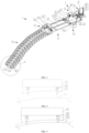
- the flexible guiding mechanism 12 is used to make the driving mechanism 11 move on the top surface 01 along the inspection channel, and the flexible guiding mechanism 12 includes a winding rack 121 and a chain 122 wound on the winding rack 121, wherein the free end of the chain 122 is fixedly connected with the front end of the driving frame 111, and the direction parallel to the upper end face of the driving frame 111 and perpendicular to the front-back direction is the left-right direction.
- the end fixed on the winding shaft 1211 of the winding rack 121 is the fixed end of the chain 122, and the other end is its free end.
- the chain 122 includes a plurality of chain plates 123 which are connected in turn in rotation, pin shafts 124 which pass through two adjacent chain plates 123, and connecting pieces 126 for connecting two pin shafts 124 adjacent to each other front and rear, and the front and rear ends of the connecting pieces 126 are rotationally connected to the same side ends of the two adjacent pin shafts 124 respectively.
- the two ends of the pin shaft 124 are rotatably connected with rollers 125 for preventing the chain plate 123 from wearing the reactor pressure vessel head, and the rollers 125 are located between the chain plate 123 and a connecting piece 126 on the same side of the chain plate 123 as the rollers 125.
- the width L2 of the chain 122 is not greater than the width LO1 of the first channel and the width L02 of the second channel.
- the width L2 of the chain 122 is less than the width LO1 of the first channel and the width L02 of the second channel, 0 ⁇ LO1-L2 ⁇ 2 mm and 0 ⁇ L02-L2 ⁇ 2 mm, and the three are of the same width is optimal.
- the chain 122 can be limited by the first channel and the second channel, it is further ensured that it moves along the length of the inspection channel.
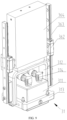
- the adjusting assembly 32 includes a first slide rail 33 fixed on the driving frame 111 and arranged along the left-right direction, a first mounting housing 34 slidably connected to the first slide rail 33, a second driving motor 35 and a probe frame 36 fixed in the first mounting housing 34 and an output shaft extending out of the first mounting housing 34, a driving gear 37 mounted on the second driving motor 35, and a rack 38 mounted on the driving frame 111 and meshed with the driving gear 37.
- the probe 31 is mounted on the probe frame 36, and the rack 38 is located below the gear and arranged along the left-right direction.
- the second driving motor 35 rotates to drive the gear to roll on the rack 38, and then the first mounting housing 34 moves on the first slide rail 33, and finally the probe frame 36 is driven left and right.
- the telescopic member 364 can be an air cylinder, a hydraulic cylinder, or a spring, which can make the probe 31 always fit the reactor pressure vessel head surface.
- the probe includes a probe body 311, a first probe mounting frame 312 fixed between the second sliding rails 363, a second probe mounting frame 313 rotatably connected to the first probe mounting frame 312, and a coupling agent connector 314 mounted on the probe body 311 for providing a coupling agent to the probe body 311, the rotating shaft of the second probe mounting frame 313 on the first probe mounting frame 312 extends along the front-back direction.
- the probe body 311 is rotatably connected to the second probe mounting frame 313.
- the limit assembly 4 includes pressing pieces 41 installed on the driving frame and located on the left and right sides of the first mounting housing 34, a trigger 42 fixed on the first mounting housing 34, and a limit switch 43 fixed on the driving frame 111 by the pressing pieces 41.
- the trigger 42 located on the left side of the first mounting housing 34 moves with the first mounting housing 34 from right to left into the trigger range of the limit switch 43 located on the left side of the driving frame 111
- the second driving motor 35 stops working, the first mounting housing 34 reaches the left limit position.
- the trigger 42 located on the right side of the first mounting housing 34 moves from left to right with the first mounting housing 34 into the trigger range of the limit switch located on the right side of the driving frame 111
- the second driving motor 35 stops working and the first mounting housing 34 reaches the right limit position.
- a positioning method for a positioning and inspection mechanism for a curved reactor pressure vessel head includes the following steps:
- the inspection method based on the positioning method described above includes the following steps:
Landscapes
- Physics & Mathematics (AREA)
- Engineering & Computer Science (AREA)
- Plasma & Fusion (AREA)
- General Engineering & Computer Science (AREA)
- High Energy & Nuclear Physics (AREA)
- Investigating Or Analyzing Materials By The Use Of Ultrasonic Waves (AREA)
- Monitoring And Testing Of Nuclear Reactors (AREA)
Applications Claiming Priority (1)
| Application Number | Priority Date | Filing Date | Title |
|---|---|---|---|
| PCT/CN2023/085520 WO2024197828A1 (fr) | 2023-03-31 | 2023-03-31 | Dispositif d'entraînement pour couvercle supérieur incurvé, vérificateur de positionnement et procédé de positionnement et de détection |
Publications (2)
| Publication Number | Publication Date |
|---|---|
| EP4546372A1 true EP4546372A1 (fr) | 2025-04-30 |
| EP4546372A4 EP4546372A4 (fr) | 2025-10-22 |
Family
ID=92903114
Family Applications (1)
| Application Number | Title | Priority Date | Filing Date |
|---|---|---|---|
| EP23929413.5A Pending EP4546372A4 (fr) | 2023-03-31 | 2023-03-31 | Dispositif d'entraînement pour couvercle supérieur incurvé, vérificateur de positionnement et procédé de positionnement et de détection |
Country Status (2)
| Country | Link |
|---|---|
| EP (1) | EP4546372A4 (fr) |
| WO (1) | WO2024197828A1 (fr) |
Families Citing this family (1)
| Publication number | Priority date | Publication date | Assignee | Title |
|---|---|---|---|---|
| CN120496898B (zh) * | 2025-07-16 | 2025-09-05 | 中广核检测技术有限公司 | 反应堆压力容器顶盖贯穿件检查装置 |
Family Cites Families (14)
| Publication number | Priority date | Publication date | Assignee | Title |
|---|---|---|---|---|
| DE2418001A1 (de) * | 1974-04-11 | 1975-10-23 | Kraftwerk Union Ag | Einrichtung zur pruefung und reparatur von unzugaenglichen oberflaechen |
| DE2849763C2 (de) * | 1978-11-16 | 1984-11-15 | Kraftwerk Union AG, 4330 Mülheim | Einrichtung zur Prüfung von mit Vorsprüngen versehenen Druckbehälterwänden |
| DE3916061B4 (de) * | 1989-05-17 | 2004-05-06 | Intelligendt Systems & Services Gmbh & Co Kg | Vorrichtung zur Prüfung einer Behälterwand |
| US5164826A (en) * | 1991-08-19 | 1992-11-17 | Westinghouse Electric Corp. | Method and apparatus for visual inspection of the internal structure of apparatus through internal passages |
| DE4226854A1 (de) * | 1992-08-13 | 1994-02-17 | Siemens Ag | Manipulator zur Inspektion schwer zugänglicher Stellen eines Dampferzeugers |
| JP2997615B2 (ja) * | 1993-12-20 | 2000-01-11 | 三菱重工業株式会社 | 検査装置 |
| JP3683665B2 (ja) * | 1997-01-13 | 2005-08-17 | 三菱電機株式会社 | 検査装置 |
| JPH10282069A (ja) * | 1997-04-07 | 1998-10-23 | Nippon Steel Corp | 超音波探傷装置及びその感度較正方法 |
| CN109975414B (zh) * | 2017-12-27 | 2024-02-09 | 核动力运行研究所 | 一种用于球面环焊缝超声检查的探头驱动装置 |
| CN207717705U (zh) * | 2017-12-27 | 2018-08-10 | 核动力运行研究所 | 一种用于球面环焊缝超声检查的探头驱动装置 |
| WO2022058767A1 (fr) * | 2020-09-15 | 2022-03-24 | Framatome | Système d'inspection non destructif pour l'inspection d'une tête de cuve de réacteur nucléaire |
| CN112298392B (zh) * | 2020-10-30 | 2022-12-06 | 中广核检测技术有限公司 | 一种磁吸附超声检查机器人 |
| CN112432999B (zh) * | 2020-10-30 | 2024-03-29 | 中广核检测技术有限公司 | 一种超声检查机器人扫查定位方法 |
| CN112461929B (zh) * | 2020-11-24 | 2024-10-25 | 中广核检测技术有限公司 | 百万千瓦级核电站辅助管道超声检查自动扫查系统 |
-
2023
- 2023-03-31 EP EP23929413.5A patent/EP4546372A4/fr active Pending
- 2023-03-31 WO PCT/CN2023/085520 patent/WO2024197828A1/fr not_active Ceased
Also Published As
| Publication number | Publication date |
|---|---|
| EP4546372A4 (fr) | 2025-10-22 |
| WO2024197828A1 (fr) | 2024-10-03 |
Similar Documents
| Publication | Publication Date | Title |
|---|---|---|
| EP4546372A1 (fr) | Dispositif d'entraînement pour couvercle supérieur incurvé, vérificateur de positionnement et procédé de positionnement et de détection | |
| CN209711124U (zh) | 一种移虫机 | |
| CN110927557B (zh) | 一种接触式芯片检测设备及方法 | |
| CN113295615B (zh) | 一种公路工程监理检验设备 | |
| WO2024188149A1 (fr) | Plateforme et dispositif d'inspection | |
| CN212780558U (zh) | Ccd视频检测装置 | |
| CN115338889B (zh) | 一种5g电力设备智能巡检控制机器人 | |
| CN116543937B (zh) | 用于曲面顶盖的驱动装置、定位检查器、定位及检测方法 | |
| US8231106B2 (en) | Synchronous moving device and image measuring apparatus | |
| CN209960152U (zh) | 一种非接触式测试装置的升降机构 | |
| CN209960151U (zh) | 一种非接触式测试装置的旋转机构 | |
| CN223610825U (zh) | 一种接触式测量机 | |
| CN219255324U (zh) | 基于光电传感器的单体组件调试定位装置 | |
| CN118024199A (zh) | 一种高负重比并联对接装配机器人 | |
| CN221325423U (zh) | 作业平台水平方向定位的定位装置 | |
| CN215954136U (zh) | 一种应于高效测试警示桩监控模主板的下载测试工装 | |
| CN223776929U (zh) | 一种喷丸图像采集装置 | |
| CN209224077U (zh) | 一种智能巡检机器人 | |
| CN223678429U (zh) | 一种航空集装板适航性检验装置 | |
| CN220270355U (zh) | 方壳电池检测装置 | |
| CN216925451U (zh) | 一种利用彩色共焦传感器快速测量z向尺寸设备 | |
| CN115046752B (zh) | 一种风电叶片自动目视检测装置及方法 | |
| CN223376756U (zh) | 一种bga虚焊检测设备 | |
| CN210570536U (zh) | 一种复合式三维影像测量仪 | |
| CN223083433U (zh) | 一种定点清理机构及设备 |
Legal Events
| Date | Code | Title | Description |
|---|---|---|---|
| STAA | Information on the status of an ep patent application or granted ep patent |
Free format text: STATUS: THE INTERNATIONAL PUBLICATION HAS BEEN MADE |
|
| PUAI | Public reference made under article 153(3) epc to a published international application that has entered the european phase |
Free format text: ORIGINAL CODE: 0009012 |
|
| STAA | Information on the status of an ep patent application or granted ep patent |
Free format text: STATUS: REQUEST FOR EXAMINATION WAS MADE |
|
| 17P | Request for examination filed |
Effective date: 20250121 |
|
| AK | Designated contracting states |
Kind code of ref document: A1 Designated state(s): AL AT BE BG CH CY CZ DE DK EE ES FI FR GB GR HR HU IE IS IT LI LT LU LV MC ME MK MT NL NO PL PT RO RS SE SI SK SM TR |
|
| A4 | Supplementary search report drawn up and despatched |
Effective date: 20250918 |
|
| RIC1 | Information provided on ipc code assigned before grant |
Ipc: G21C 17/003 20060101AFI20250912BHEP Ipc: G01N 33/00 20060101ALI20250912BHEP Ipc: G21C 17/007 20060101ALI20250912BHEP |