EP4546455A1 - Matériau composite de silicium-carbone et son procédé de préparation, et batterie secondaire comprenant un matériau composite de silicium-carbone - Google Patents
Matériau composite de silicium-carbone et son procédé de préparation, et batterie secondaire comprenant un matériau composite de silicium-carbone Download PDFInfo
- Publication number
- EP4546455A1 EP4546455A1 EP22954624.7A EP22954624A EP4546455A1 EP 4546455 A1 EP4546455 A1 EP 4546455A1 EP 22954624 A EP22954624 A EP 22954624A EP 4546455 A1 EP4546455 A1 EP 4546455A1
- Authority
- EP
- European Patent Office
- Prior art keywords
- silicon
- carbon
- carbon composite
- matrix particles
- optionally
- Prior art date
- Legal status (The legal status is an assumption and is not a legal conclusion. Google has not performed a legal analysis and makes no representation as to the accuracy of the status listed.)
- Pending
Links
Images

Classifications
-
- C—CHEMISTRY; METALLURGY
- C01—INORGANIC CHEMISTRY
- C01B—NON-METALLIC ELEMENTS; COMPOUNDS THEREOF; METALLOIDS OR COMPOUNDS THEREOF NOT COVERED BY SUBCLASS C01C
- C01B32/00—Carbon; Compounds thereof
- C01B32/05—Preparation or purification of carbon not covered by groups C01B32/15, C01B32/20, C01B32/25, C01B32/30
-
- H—ELECTRICITY
- H01—ELECTRIC ELEMENTS
- H01M—PROCESSES OR MEANS, e.g. BATTERIES, FOR THE DIRECT CONVERSION OF CHEMICAL ENERGY INTO ELECTRICAL ENERGY
- H01M10/00—Secondary cells; Manufacture thereof
- H01M10/05—Accumulators with non-aqueous electrolyte
- H01M10/052—Li-accumulators
- H01M10/0525—Rocking-chair batteries, i.e. batteries with lithium insertion or intercalation in both electrodes; Lithium-ion batteries
-
- H—ELECTRICITY
- H01—ELECTRIC ELEMENTS
- H01M—PROCESSES OR MEANS, e.g. BATTERIES, FOR THE DIRECT CONVERSION OF CHEMICAL ENERGY INTO ELECTRICAL ENERGY
- H01M4/00—Electrodes
- H01M4/02—Electrodes composed of, or comprising, active material
- H01M4/13—Electrodes for accumulators with non-aqueous electrolyte, e.g. for lithium-accumulators; Processes of manufacture thereof
- H01M4/134—Electrodes based on metals, Si or alloys
-
- H—ELECTRICITY
- H01—ELECTRIC ELEMENTS
- H01M—PROCESSES OR MEANS, e.g. BATTERIES, FOR THE DIRECT CONVERSION OF CHEMICAL ENERGY INTO ELECTRICAL ENERGY
- H01M4/00—Electrodes
- H01M4/02—Electrodes composed of, or comprising, active material
- H01M4/36—Selection of substances as active materials, active masses, active liquids
-
- H—ELECTRICITY
- H01—ELECTRIC ELEMENTS
- H01M—PROCESSES OR MEANS, e.g. BATTERIES, FOR THE DIRECT CONVERSION OF CHEMICAL ENERGY INTO ELECTRICAL ENERGY
- H01M4/00—Electrodes
- H01M4/02—Electrodes composed of, or comprising, active material
- H01M4/36—Selection of substances as active materials, active masses, active liquids
- H01M4/362—Composites
- H01M4/364—Composites as mixtures
-
- H—ELECTRICITY
- H01—ELECTRIC ELEMENTS
- H01M—PROCESSES OR MEANS, e.g. BATTERIES, FOR THE DIRECT CONVERSION OF CHEMICAL ENERGY INTO ELECTRICAL ENERGY
- H01M4/00—Electrodes
- H01M4/02—Electrodes composed of, or comprising, active material
- H01M4/36—Selection of substances as active materials, active masses, active liquids
- H01M4/38—Selection of substances as active materials, active masses, active liquids of elements or alloys
- H01M4/386—Silicon or alloys based on silicon
-
- H—ELECTRICITY
- H01—ELECTRIC ELEMENTS
- H01M—PROCESSES OR MEANS, e.g. BATTERIES, FOR THE DIRECT CONVERSION OF CHEMICAL ENERGY INTO ELECTRICAL ENERGY
- H01M4/00—Electrodes
- H01M4/02—Electrodes composed of, or comprising, active material
- H01M4/36—Selection of substances as active materials, active masses, active liquids
- H01M4/58—Selection of substances as active materials, active masses, active liquids of inorganic compounds other than oxides or hydroxides, e.g. sulfides, selenides, tellurides, halogenides or LiCoFy; of polyanionic structures, e.g. phosphates, silicates or borates
- H01M4/583—Carbonaceous material, e.g. graphite-intercalation compounds or CFx
- H01M4/587—Carbonaceous material, e.g. graphite-intercalation compounds or CFx for inserting or intercalating light metals
-
- H—ELECTRICITY
- H01—ELECTRIC ELEMENTS
- H01M—PROCESSES OR MEANS, e.g. BATTERIES, FOR THE DIRECT CONVERSION OF CHEMICAL ENERGY INTO ELECTRICAL ENERGY
- H01M4/00—Electrodes
- H01M4/02—Electrodes composed of, or comprising, active material
- H01M4/62—Selection of inactive substances as ingredients for active masses, e.g. binders, fillers
- H01M4/624—Electric conductive fillers
- H01M4/625—Carbon or graphite
-
- C—CHEMISTRY; METALLURGY
- C01—INORGANIC CHEMISTRY
- C01P—INDEXING SCHEME RELATING TO STRUCTURAL AND PHYSICAL ASPECTS OF SOLID INORGANIC COMPOUNDS
- C01P2006/00—Physical properties of inorganic compounds
- C01P2006/40—Electric properties
-
- H—ELECTRICITY
- H01—ELECTRIC ELEMENTS
- H01M—PROCESSES OR MEANS, e.g. BATTERIES, FOR THE DIRECT CONVERSION OF CHEMICAL ENERGY INTO ELECTRICAL ENERGY
- H01M4/00—Electrodes
- H01M4/02—Electrodes composed of, or comprising, active material
- H01M2004/021—Physical characteristics, e.g. porosity, surface area
-
- H—ELECTRICITY
- H01—ELECTRIC ELEMENTS
- H01M—PROCESSES OR MEANS, e.g. BATTERIES, FOR THE DIRECT CONVERSION OF CHEMICAL ENERGY INTO ELECTRICAL ENERGY
- H01M4/00—Electrodes
- H01M4/02—Electrodes composed of, or comprising, active material
- H01M2004/026—Electrodes composed of, or comprising, active material characterised by the polarity
- H01M2004/027—Negative electrodes
-
- H—ELECTRICITY
- H01—ELECTRIC ELEMENTS
- H01M—PROCESSES OR MEANS, e.g. BATTERIES, FOR THE DIRECT CONVERSION OF CHEMICAL ENERGY INTO ELECTRICAL ENERGY
- H01M2220/00—Batteries for particular applications
- H01M2220/20—Batteries in motive systems, e.g. vehicle, ship, plane
-
- Y—GENERAL TAGGING OF NEW TECHNOLOGICAL DEVELOPMENTS; GENERAL TAGGING OF CROSS-SECTIONAL TECHNOLOGIES SPANNING OVER SEVERAL SECTIONS OF THE IPC; TECHNICAL SUBJECTS COVERED BY FORMER USPC CROSS-REFERENCE ART COLLECTIONS [XRACs] AND DIGESTS
- Y02—TECHNOLOGIES OR APPLICATIONS FOR MITIGATION OR ADAPTATION AGAINST CLIMATE CHANGE
- Y02E—REDUCTION OF GREENHOUSE GAS [GHG] EMISSIONS, RELATED TO ENERGY GENERATION, TRANSMISSION OR DISTRIBUTION
- Y02E60/00—Enabling technologies; Technologies with a potential or indirect contribution to GHG emissions mitigation
- Y02E60/10—Energy storage using batteries
Definitions
- the present application belongs to the technical field of battery, in particular to a silicon-carbon composite, a method of preparing the same, and a secondary battery comprising the silicon-carbon composite.
- Secondary batteries have properties such as high capacity and long life, and thus are widely used in electronic devices such as cellular phones, laptop computers, battery operated vehicles, electric cars, electric airplanes, electric boats, electric toy cars, electric toy boats, electric toy airplanes, and power tools, among others. Due to great progress made in secondary batteries, performances of secondary batteries are required to be higher. In order to improve energy density of secondary batteries, silicon-based negative electrode active materials are currently considered in the industry, but the silicon-based materials would produce large own expansion although they have a higher specific capacity, which seriously affects cycle performance of batteries.
- An object of the present application is to provide a silicon-carbon composite, a method for preparing the same, and a secondary battery comprising the silicon-carbon composite, such that the secondary battery can have a better cycle performance and a higher energy density both.
- a first aspect of the present application provides a silicon-carbon composite, the silicon-carbon composite comprising carbon-based matrix particles, the carbon-based matrix particles comprising a three-dimensional network interconnecting pore structure; and silicon-based nanoparticles, at least a portion of which is provided in the three-dimensional network interconnecting pore structure.
- the carbon-based matrix particles of the present application have a stable porous skeleton structure, which has a stronger support capacity, exhibits a higher resistance to stress, and has excellent mechanical properties and electrical conductivity.
- the carbon-based matrix particles comprise a three-dimensional network interconnecting pore structure, which allows more space for the silicon-based nanoparticles to be set up, and can be used for storage of a large amount of silicon.
- the silicon-based nanoparticles Upon compounding the porous carbon-based matrix particles with the silicon-based nanoparticles, the silicon-based nanoparticles are not easy to agglomerate, and can be uniformly dispersed in pores of the carbon-based matrix particles.
- the resulting silicon-carbon composite can have an improved electrical conductivity while the carbon matrix particle may alleviate volume change of silicon in the process of intercalation-deintercalation of lithium and fully withstand stress changes of the silicon-based nanoparticles, ensuring structural stability of the silicon-carbon composites, and improving cycle stability and lithium storage of the silicon-carbon composites.
- secondary batteries adopting the silicon carbon composite has improved cycle performance and energy density.
- At least a portion of pores in a surface region of the carbon-based matrix particles have a pore size larger than pores in an internal region of the carbon-based matrix particles.
- the three-dimensional network interconnecting pore structure exhibits a laminar distribution in the carbon-based matrix particles.
- the silicon-carbon composite has a powder compaction density denoted as P 11 after subjected to powder pressing once under a force of 20,000N, the silicon-carbon composite has a powder compaction density enoted as P 21 after subjected to powder pressing 20 times under a force of 20,000N, and the silicon-carbon composite satisfies: 1.00 ⁇ P 21 /P 11 ⁇ 1.20; optionally, 1.02 ⁇ P 21 /P 11 ⁇ 1.10.
- the silicon-carbon composite of the present application has a specific structure, and the powder compaction density under the above test conditions meets a specific requirement, so that the silicon-carbon composite has a higher specific capacity while further having a better compression resistance, which effectively ensures structural stability of the negative electrode film layer, so as to enable the secondary battery containing the material to have a higher energy density and a better cycle performance.
- the silicon-carbon composite has a powder compaction density denoted as P 11 in g/cm 3 under a force of 20,000N, then the silicon-carbon composite satisfies: 1.10 ⁇ P 11 ⁇ 1.40; optionally, 1.12 ⁇ P 11 ⁇ 1.35.
- the carbon-based matrix particles have a moderate pore size distribution, which is conducive to subsequent incorporation of a silicon-containing precursor into pores of the carbon-based matrix particles, and reduces the risk of silicon being deposited on surface of the carbon-based matrix particles; and which is also conducive to deposition on the carbon-based matrix particles towards saturation so as to enable the resulting silicon carbon composite particles formed after the deposition of silicon to have an appropriate specific surface area, and ensure its reversible capacity.
- the carbon-based matrix particles have a total volume of pores with a diameter greater than 100 nm, noted as V 1 cm 3 /g, as measured using a gas adsorption-desorption method and V 1 ⁇ 0.01, and optionally, 0.01 ⁇ V 1 ⁇ 0.5.
- the carbon-based matrix particles have a total volume of pores with a diameter less than or equal to 100 nm, noted as V 2 cm 3 /g, as measured using a gas adsorption-desorption method and V 2 ⁇ 0.05, and optionally, 0.05 ⁇ V 1 ⁇ 1.1.
- the carbon-based matrix particles have a porosity, noted as W, of 40% ⁇ W ⁇ 80%; optionally, 50% ⁇ W ⁇ 70%.
- the carbon-based matrix particles in the present application has a porosity satisfying the above range, its pores occupy an appropriate volume in its skeleton structure, which can ensure stability of the skeleton structure and further provide accommodation for deposited silicon.
- the silicon-based nanoparticles are attached to the pores, and the silicon-based nanoparticles and the porous carbon-based matrix particles can function synergistically so as to improve capacity and electrical conductivity of the silicon-carbon composite.
- the carbon-based matrix particles have a powder compaction density under a force of 50,000 N, noted as P g/cm 3 , of 0.4 ⁇ P ⁇ 1.1; optionally, 0.6 ⁇ P ⁇ 0.9.
- the carbon-based matrix particles have a real density, noted as ⁇ g/cm3, of 1.7 ⁇ 2.5; optionally, 1.9 ⁇ 2.2.
- the carbon-based matrix particles include one or more of graphite, soft carbon, and hard carbon.
- the silicon-based nanoparticles comprise one or more of a silicon-oxygen compound, a pre-lithiated silicon-oxygen compound, amorphous silicon, crystalline silicon, and a silicon-carbon composite; optionally, the silicon-based nanoparticles comprise amorphous silicon.
- the silicon-based nanoparticles have a mass percentage in the silicon-carbon composite of greater than or equal to 40%; optionally 40%-60%.
- the silicon-based nanoparticles when the silicon-based nanoparticles have a mass percentage within the above range in the silicon-carbon composite, the silicon-carbon composite has a relatively high capacity.
- the silicon-carbon composite has a volume particle size Dv10 satisfying Dv10 ⁇ 5 ⁇ m; optionally, 3 ⁇ m ⁇ Dv10 ⁇ 5 ⁇ m.
- the silicon-carbon composite has a volume particle size Dv50 satisfying Dv50 ⁇ 10 ⁇ m; optionally, 5 ⁇ m ⁇ Dv50 ⁇ 8 ⁇ m.
- the silicon-carbon composite has a volume particle size Dv90 satisfying Dv90 ⁇ 20 ⁇ m; optionally, 8 ⁇ m ⁇ Dv90 ⁇ 18 ⁇ m.
- the silicon-carbon composite has a particle size distribution satisfying (Dv90-Dv10)/Dv50 ⁇ 1.6; optionally, 1.4 ⁇ (Dv90-Dv10)/Dv50 ⁇ 1.6.
- the silicon-carbon composite of the present application When the particle size of the silicon-carbon composite of the present application satisfies the above range, the silicon-carbon composite has a relatively stable structure and a better dynamic performance, which is conducive to improving first Coulomb efficiency of the silicon-carbon composite.
- the silicon-carbon composite has a specific surface area SSA satisfying: 2 m 2 /g ⁇ SSA ⁇ 10 m 2 /g; optionally, 3 m 2 /g ⁇ SSA ⁇ 7 m 2 /g.
- the specific surface area SSA of the silicon-carbon composite of the present application satisfies the above range, the specific surface area has a moderate range, and the material has a better dynamic performance, which is conducive to first Coulomb efficiency of the material.
- a second aspect of the present application provides a method of preparing a silicon-carbon composite comprising the steps of: mixing a crosslinking resin, a porogenic agent and a solvent to form a hybrid system; preheating the hybrid system to volatilize the solvent and allow the crosslinking resin to cure to form a solid resin; breaking the solid resin to form a granular resin; carbonizing the granular resin to volatilize the porogenic agent and to etch the granular resin to form carbon-based matrix particles having a three-dimensional crosslinked network structure; and generating silicon-based nanoparticles by chemical vapor deposition from a gas comprising a silicon precursor, with at least a portion of the silicon-based nanoparticles attached to pores of the carbon-based matrix particles.
- the crosslinking resin is added in a mass content, noted as a1, based on the total mass of the hybrid system; the solvent is added in a mass content, noted as a2, based on the total mass of the hybrid system; and the hybrid system satisfies: 0.1 ⁇ a1/a2 ⁇ 10; optionally, 0.5 ⁇ a1/a2 ⁇ 2.
- the mass content of the crosslinking resin and the mass content of the solvent are controlled within the above range in the present application, it is allowed to ensure that the solvent can fully dissolve the crosslinking resin and the porogenic agent, and that the three components form a homogeneous hybrid system; and it is allowed to form a pore channel with a suitable pore size during evaporation of the solvent, and that the solid resin formed has a good mechanical strength.
- the crosslinking resin is added in a mass content, noted as a1, based on the total mass of the hybrid system; the porogenic agent is added in a mass content, noted as a3, based on the total mass of the hybrid system; and the hybrid system satisfies: 0.1 ⁇ a1/a3 ⁇ 5; optionally, 0.5 ⁇ a1/a3 ⁇ 3.
- the mass content of the crosslinking resin and the mass content of the porogenic agent are controlled within the above range in the present application, it is conducive to absorption of water by the porogenic agent to promote curing of the crosslinking resin; and it is allowed to ensure the formation of a pore channel with a relatively small pore size during the carbonization process.
- the preheating step is carried out at a temperature of 60°C to 120°C, optionally 60°C to 80°C.
- the preheating step is carried out for a period of t1 ⁇ 10 h, optionally 15h to 20h.
- the carbonizing step comprises a first carbonizing step and a second carbonizing step, in which the first carbonizing step is carried out at a temperature of 500°C to 800°C, and the first carbonizing step is carried out at a period of 2h to 3h; and/or, the second carbonizing step is carried out at a temperature of 800°C to 1000°C, and the second carbonizing step is carried out at a period of 3h to 5h.
- the first carbonizing step may be carried out at a constant temperature, during which a slow vaporization process of the porogenic agent may occur, and in the process of vaporization and volatilization of the porogenic agent, the porogenic agent etches internal structure of the resin so as to form pores with a relatively small pore size, and a pore structure in an overall homogenous form, thereby constituting a preliminary carbon skeleton structure.
- the second carbonizing step is carried out a relatively high temperature, during which the porogenic agent can be quickly vaporized, which is conducive to a rapid completion of the pore-forming process.
- it is allowed to ensure stability of skeleton structure of the porous carbon-based matrix particles as well as a suitable porosity.
- the silicon precursor is added in an amount of greater than or equal to 40%; optionally, from 40% to 60%.
- the addition amount of the silicon precursor satisfies the above range, it is possible to enable silicon based nanoparticles to be uniformly dispersed in pores of the carbon-based matrix particles, thereby ensuring capacity of the silicon-carbon composite.
- the chemical vapor deposition is carried out at a deposition temperature of less than or equal to 600°C; optionally, of 450°C to 550°C.
- the deposition temperature ensures silicon nanoparticles to be effectively generated from the silicon precursor and to be deposited within the carbon-based matrix particles.
- a third aspect of the present application provides a secondary battery comprising a negative electrode plate comprising the silicon-carbon composite in any embodiment of the first aspect of the present application, or the silicon-carbon composite prepared by the method in any embodiment of the second aspect of the present application.
- a fourth aspect of the present application provides an electrical device comprising the secondary battery of the third aspect of the present application.
- ranges are defined in the form of lower and upper limits, and a given range is defined by selection of a lower limit and an upper limit that define boundary of the particular range. Ranges defined in this manner may or may not be inclusive of the endpoints, and may be arbitrarily combined. That is, any lower limit may be combined with any upper limit to form a range. For example, if the ranges of 60-120 and 80-110 are listed for a particular parameter, it is to be understood that the ranges of 60-110 and 80-120 are also contemplated.
- the numerical range "a-b" represents an abbreviated representation of any combination of real numbers between a and b, where both a and b are real numbers.
- the numerical range "0-5" means that all real numbers between "0-5" have been listed herein, and the range "0-5" is just an abbreviated representation of the combination of these numerical values.
- a parameter is expressed as an integer greater than or equal to 2, it is equivalent to disclose that the parameter is, for example, an integer of 2, 3, 4, 5, 6, 7, 8, 9, 10, 11, 12, and the like.
- the method includes steps (a) and (b), indicating that the method may include steps (a) and (b) performed in sequence, or that the method may include steps (b) and (a) performed in sequence.
- step (c) indicates that step (c) may be added to the method in any order.
- the method may comprises steps (a), (b) and (c), steps (a), (c) and (b), or steps (c), (a) and (b), and the like.
- transition phases “comprise”, “comprising”, “contain” and “containing” mentioned in the present application mean that it is drafted in an open mode, or it may also mean a close mode.
- the transition phases “comprise”, “comprising”, “contain” and “containing” may mean that other components not listed may also be included or contained, or only the listed components may be included or contained.
- the term "or” is inclusive.
- the phrase “A or B” means “A, B, or both A and B”. More specifically, any of the following conditions meets “A or B”: A is true (or present) and B is false (or absent); A is false (or absent) and B is true (or present); or both A and B are true (or present).
- Negative electrode active materials have a significant impact on performances of secondary batteries, and carbon and silicon have been widely studied as common materials for negative electrode active materials.
- the carbon particles have a low theoretical specific capacity, and low lithium intercalation potential, which is easy to cause lithium precipitation and safety problems.
- Silicon at room temperature may form silicon lithium alloy with lithium, and has a relatively high theoretical specific capacity; and silicon has a slightly higher lithium intercalation potential than graphite, and thus can reduce the risk of lithium precipitation.
- micron-sized silicon material in the process of intercalation and deintercalation of lithium has a volume change of greater than 300%, i.e. a large volume change.
- the silicon particles whose volume continues to change are likely to cause rupture and regeneration of solid electrolyte interface membrane (Solid-Electrolyte Interphase, SEI membrane) on the surface of active material, and the continuous growth of the SEI membrane not only will continue to consume lithium and electrolyte, but also limit transmission of lithium ions, reduce electrical contact of the active material, and increase impedance.
- SEI membrane Solid-Electrolyte Interphase
- the inventors make an improved silicon-carbon composite based on carbon-based matrix particles having a three-dimensional network interconnecting pore structure within which silicon-based nanoparticles are formed, wherein more than two pores of the carbon-based matrix particles are interlaced and connected with each other, which can provide more space for the silicon-based nanoparticles, and can be used for storage of a large amount of silicon.
- the silicon-based nanoparticles are not easy to agglomerate, and can be uniformly dispersed in pores of the carbon-based matrix particles.
- the resulting silicon-carbon composite can have an improved electrical conductivity and meanwhile the carbon matrix particle may alleviate volume change of silicon in the process of intercalation-deintercalation of lithium and fully withstand stress changes of the silicon-based nanoparticles, ensuring structural stability of the silicon-carbon composite, and improving cycle stability and storage lithium capacity of the silicon-carbon composites.
- secondary batteries adopting the silicon carbon composite has improved cycle performance and energy density.
- the present application provides a silicon-carbon composite, the silicon-carbon composite comprising carbon-based matrix particles, the carbon-based matrix particles comprising a three-dimensional network interconnecting pore structure; and silicon-based nanoparticles, at least a portion of which is provided in the three-dimensional network interconnecting pore structure.
- the three-dimensional network interconnecting pore structure typically refers to a structure in which two or more pores are interconnected or staggered and share pore volume with each other in the pore structure as formed of the carbon-based matrix particles.
- the carbon-based matrix particles of the present application have a stable porous skeleton structure, which has a strong support capacity, exhibits a high stress capacity, and has excellent mechanical properties and electrical conductivity.
- the carbon-based matrix particles comprise a three-dimensional network interconnecting pore structure, which allows more space for the silicon-based nanoparticles to be set up, and can be used for storage of a large amount of silicon.
- the silicon-based nanoparticles are not easy to agglomerate, and can be uniformly dispersed in pores of the carbon-based matrix particles.
- the resulting silicon-carbon composite can have an improved electrical conductivity while the carbon matrix particle may alleviate volume change of silicon in the process of intercalation-deintercalation of lithium and fully withstand stress changes of the silicon-based nanoparticles, ensuring structural stability of the silicon-carbon composites, and improving cycle stability and lithium capacity of the silicon-carbon composites.
- secondary batteries adopting the silicon carbon composite has improved cycle performance and energy density.
- the pore structure of the silicon-carbon composite can be tested using equipment and methods known in the art. For example, it can be measured by using a scanning electron microscope (e.g., a ZEISS Sigma 300). As an example, the testing can be done in the following steps: first of all, a negative electrode plate comprising the silicon-carbon composite is cut into a sample to be tested of a certain size (e.g., 6mm x 6mm), the sample to be tested is clamped with two thermally conductive sheets (e.g., copper foil) and is fixed with an adhesive (e.g., double-sided adhesive) to the sheets, on which a certain mass (e.g., about 400g) of a leveling iron is placed for a certain period (e.g., 1h ), so that the gap between the sample to be tested and the copper foil would be as small as possible, and then the edge of the sample are cut with scissors, and the resulting sample is adhere to a sample stage with a conductive adhesive, with the sample slightly protruding the sample
- the sample stage is loaded into a sample rack and lock fixed, and then turn on an argon ion cross-section polisher (such as IB-19500CP) power and vacuum (e.g., 10 Pa -4Pa), set an argon flow (e.g., 0.15MPa) and a voltage (e.g., 8KV) and a polishing time (e.g., 2 hours), adjust the sample stage in a swing mode to start polishing.
- a scanning electron microscope e.g., ZEISS Sigma 300
- CP ion-polished cross-section topography
- the inventors of the present application have found, after thorough research, that when the silicon-carbon composite of the present application satisfy the above-described design, it may further improve performances of batteries can be further improved if optionally satisfying one or more of the following parameters.
- a pore size of at least a portion of pores in a surface region of the carbon-based matrix particles is larger than a pore size of pores in an interior region of the carbon-based matrix particles.
- the surface region is a region comprising a depth of 500 nm-800 nm extending from a surface of the carbon-based matrix particles toward interior of the particles; and the interior region is other regions of the carbon-based matrix particles than the surface region.
- the three-dimensional network interconnecting pore structure exhibits a laminar distribution in the carbon-based matrix particles.
- the silicon-carbon composite satisfies: 1.00 ⁇ P 21 /P 11 ⁇ 1.20; optionally, 1.02 ⁇ P 21 /P 11 ⁇ 1.10, in which P 11 in g/cm 3 denotes a powder compaction density of the silicon-carbon composite after undergoing 20-second press once under a force of 20,000N, and P 21 in g/cm 3 denotes a powder compaction density of the silicon-carbon composite after undergoing 20-second press under a force of 20,000N for 20 times.
- P 21 /P 11 When P 21 /P 11 is denoted as M, the value of M can be used to indicate the change in stress-strain capacity during compaction of the silicon-carbon composite.
- the silicon-carbon composite When the value of M is within the range described above, the silicon-carbon composite has a relatively strong compression resistance, so as to enable the negative electrode active material adopting the silicon-carbon composite to have an improved compression resistance and to ensure structural stability of the negative electrode film layer, which in turn further improves cycle performances of batteries.
- P 21 /P 11 may be 1.00, 1.02, 1.10, or 1.20. When P 21 /P 11 is 1.00, it indicates that the silicon-carbon composite has a better compression resistance and is less prone to compression deformation.
- the powder compaction density of material has a known meaning in the art and can be tested by methods known in the art. For example, it can be tested with reference to GB/T 24533-2009, with an electronic pressure testing machine (e.g., UTM7305): a certain mass G of a powder sample to be tested is placed on a special mold for compaction with a bottom area S, different pressures are set (20,000N or 50,000N can be used in this application) and held for 20s.
- UTM7305 electronic pressure testing machine
- the compaction density at that pressure G/(H*S).
- the silicon-carbon composite of the present application has a specific structure, and the powder compaction density of the silicon-carbon composite under the above test conditions is controlled within a particular range, it is allowed that the silicon-carbon composite has a higher specific capacity while further having a better compression resistance, which effectively ensures structural stability of the negative electrode film layer, so as to enable the secondary battery containing the material to have a higher energy density and a better cycle performance.
- the carbon-based matrix particles have a total volume of pores with a diameter greater than 100 nm, noted as V 1 cm 3 /g, the carbon-based matrix particles have a total volume of pores with a diameter less than or equal to 100 nm, noted as V 2 cm 3 /g, and the carbon-based matrix particles satisfy: 1 ⁇ V 2 /V 1 ⁇ 30; optionally, 3 ⁇ V 2 / V 1 ⁇ 25.
- V 2 / V 1 may be 1.5, 2.5, 2.8, 3.0, 3.5, 4, 4.5, 5, 6, 7, 8, 9, 10, 15, 20, or 25; or a range constituted by any two of the above values.
- the carbon-based matrix particles By regulating the ratio of the total volume of pores having a specific size in the porous carbon-based matrix particles, it is allowed to ensure that the carbon-based matrix particles have a moderate pore size distribution, which is conducive to subsequent incorporation of a silicon-containing precursor into pores of the carbon-based matrix particles, and reduces the risk of silicon being deposited on surface of the carbon-based matrix particles; and which is also conducive to deposition on the carbon-based matrix particles towards saturation so as to enable the resulting silicon carbon composite particles formed after the deposition of silicon to have an appropriate specific surface area, and ensure its reversible capacity.
- the above total volume of pores can be determined using instruments and methods well known in the art.
- the method can refer to GB/T 19587-2004, and a mesoporous pore size distribution test of BJH (Barret joyner Halenda) is adopted, in which a gas adsorption and desorption method under a micro-mesoporous model is adopted for testing and adsorption data is chosen for the determination and counting of the total volume V1 of pores with a diameter greater than 100 nm and the total volume V2 of pores with a diameter equal to or less than 100 nm
- BJH Barret joyner Halenda
- the carbon-based matrix particles have a total volume of pores with a pore diameter greater than 100 nm, noted as V 1 cm 3 /g, as measured using a gas adsorption-desorption method and V 1 ⁇ 0.01, and optionally, 0.01 ⁇ V 1 ⁇ 0.5.
- the carbon-based matrix particles have a total volume of pores with a diameter less than or equal to 100 nm, noted as V 2 cm 3 /g, as measured using a gas adsorption-desorption method and V 2 ⁇ 0.05, and optionally, 0.05 ⁇ V 2 ⁇ 1.1.
- the carbon-based matrix particles have a porosity, noted as W, of 40% ⁇ W ⁇ 80%; optionally, 50% ⁇ W ⁇ 70%.
- the carbon-based matrix particles in the present application has a porosity satisfying the above range, its pores occupy an appropriate volume in its skeleton structure, which can ensure stability of the skeleton structure and further provide accommodation for deposited silicon.
- the silicon-based nanoparticles are attached to the pores, and the silicon-based nanoparticles and the porous carbon-based matrix particles can function synergistically so as to improve capacity and electrical conductivity of the silicon-carbon composite.
- the porosity W% of the porous carbon-based matrix particles may be 10%, 15%, 20%, 25%, 30%, 35%, 40%, 45%, 50%, 55%, 60%, 65%, 70%, 75%, or 80%; or a range constituted by any two of the above value.
- the porosity refers to a ratio of the volume of pores inside particles occupying the total volume of the carbon-based matrix particles.
- the carbon-based matrix particles have a powder compaction density under a force of 50,000 N, noted as P g/cm 3 , of 0.4 ⁇ P ⁇ 1.1; optionally, 0.6 ⁇ P ⁇ 0.9 wherein P may be tested in accordance with the method of testing powder compaction density of materials provided above.
- the powder compaction density of the carbon-based matrix particles By adjusting the powder compaction density of the carbon-based matrix particles within a suitable range, it is allowed to enable a negative electrode film layer to have a high compaction density, which in turn ensures that secondary batteries have a high energy density.
- the powder compaction density of the carbon-based matrix particles within a suitable range it is also possible to make the negative electrode film layer have a stronger ability to maintain its pore structure during a cycle process, whereby the negative electrode plate has a better electrolyte wettability, which can better enhance cycle performance of secondary batteries.
- the powder compaction density P in g/cm 3 under a force of 50,000 N may be 0.6 g/cm 3 , 0.65 g/cm 3 , 0.7 g/cm 3 , 0.75 g/cm 3 , 0.8 g/cm 3 , 0.85 g/cm 3 , 0.9 g/cm 3 , 1.0 g/cm 3 , or 1.1 g/cm 3 ; or a range constituted by any two of the above value.
- the carbon-based matrix particles have a real density, noted as ⁇ g/cm3, of 1.7 ⁇ 2.5; optionally, 1.9 ⁇ 2.3.
- the real density ⁇ in g/cm 3 of the carbon-based matrix particles may be 1.7 g/cm 3 , 1.8 g/cm 3 , 1.9 g/cm 3 , 2.0 g/cm 3 , 2.1 g/cm 3 , 2.2 g/cm 3 , 2.3 g/cm 3 , 2.4 g/cm 3 , or 2.5 g/cm 3 ; or a range consisting of any two of the above values.
- the real density of material has a known meaning in the art, which refers to an actual mass of solid material per unit volume in an absolutely dense state, i.e., a density of materials after removing the internal voids of the materials or the voids between particles; and which may be tested using instruments and methods known in the art.
- the test method may refer to GB/T 24586-2009, and the test instrument may adopt a real density tester.
- the sample cup can be operated in accordance with the following steps: take a clean and dry sample cup and place it on a balance with a target operation, add a certain amount of powder sample to the sample cup (e.g., the sample can account for 1/2 of volume of the sample cup), record the mass of the sample taken, place the sample cup containing the sample on a True Density Tester in a sealed condition, fill with helium gas, detect pressure of the gas in a sample chamber and an expansion chamber, then calculate a real volume according to Bohr's law to calculate the real density.
- the carbon-based matrix particles include one or more of graphite, soft carbon, and hard carbon.
- the above materials when prepared into a porous structure, are favorable for placement of silica-based nanoparticles in pores of the porous structures; and their structural stability is relatively high.
- the silicon-based nanoparticles comprise one or more of a silicon-oxygen compound, a pre-lithiated silicon-oxygen compound, amorphous silicon, crystalline silicon, and a silicon-carbon composite; optionally, the silicon-based nanoparticles comprise amorphous silicon.
- the amorphous silicon can expand uniformly in all directions, thereby causing uniform extrusion on the porous carbon-based matrix particles, and the porous carbon-based matrix particles can effectively alleviate volume expansion of the amorphous silicon.
- the crystalline silicon has a relatively more stable structure, which is more conducive to fully exerting its capacity characteristics.
- the silicon-carbon complex is formed in pores of the porous carbon-based matrix particles after carbon and silicon are compounded as a compound in advance, and its volume expansion is relatively small, which can alleviate stress caused to the porous carbon-based matrix particles.
- the silicon-carbon complex may be silicon carbide.
- a shiny surface taking an appropriate amount of a silicon particles sample (e.g., 1 g) and adding it to a beaker containing an appropriate amount of ethanol, and ultrasonically oscillating it for 10 min to 30 min; then dropping 2-3 drops of the sample to be tested on the microgrid using a glass capillary tube; after oven baking for 5 minutes, placing the microgrid with the sample drops to be tested on the sample stage, and then observing it with a transmission electron microscope (e.g., Hitachi HF-3300S Cs-corrected STEM) at a certain magnification (e.g., 60,000 ⁇ ), to obtain transmission electron microscopy (TEM) image of the sample to be tested. If there are distinct lattice stripes (e.g., a spacing between the stripes is approximately equal to 0.331 nm), the sample is crystalline silicon; if no lattice fringes are observed, the sample is amorphous silicon.
- a transmission electron microscope e.g., Hitachi HF-3300S Cs
- the silicon-based nanoparticles have a mass percentage in the silicon-carbon composite of greater than or equal to 40%; optionally 40%-60%.
- the silicon-carbon composite has a relatively high capacity.
- the mass of the silicon-based nanoparticles in the silicon-carbon composite can be tested using methods and equipment known in the art. For example, it can be determined with reference to the EPA 6010D-2014. Specifically, it can be tested using ICP-OES (Elemental Analysis - Inductively Coupled Plasma Emission Spectrometry), whereby solid to be tested is first dissolved into a liquid with a strong acid, and then subsequently, the liquid is introduced into a ICP light source by way of atomization, and further the gaseous atoms to be tested are restored from the excited state to the ground state after ionization and excitation in a strong magnetic field; energy is released in the above process and recorded as different characteristic spectral lines for quantitative analysis of trace elements.
- ICP-OES Simple Analysis - Inductively Coupled Plasma Emission Spectrometry
- the mass of carbon element in the silicon-carbon composite can be tested using methods and equipment known in the art.
- a TG (Thermal Weight Loss) test can be used, whereby the silicon-carbon composite as a sample is heat-treated under oxygen-containing conditions (ramping up to 1000°C from 25°C), the masses of the sample before and after the heat-treatment are recorded, and the difference between the masses of the sample before and after the heat-treatment is the mass of carbon that has been burned away, from which it can be known the carbon content in the sample.
- the silicon-based nanoparticles have a particle size, noted as Dsi in nm, Dsi ⁇ 100; optionally, 2 ⁇ Dsi ⁇ 80.
- the silicon-based nanoparticles having a relatively small particle size can significantly alleviate higher pressure caused by change in the volume of silicon, which is conducive to ensuring an overall structural stability of the silicon-carbon composite, and improving a cycle stability of secondary batteries; and it can significantly shorten transmission distance of lithium ions, which is conducive to improving kinetic performance of the silicon-carbon composite.
- the particle size of the silicon-based nanoparticles may be 2 nm, 3 nm, 5 nm, 8 nm, 10 nm, 12 nm, 15 nm, 20 nm, 25 nm, 30 nm, 40 nm, 50 nm, 60 nm, 70 nm, or 80 nm; or a range consisting of any two of the above values.
- the particle size of the silicon-based nanoparticles can be determined by measuring an XRD pattern of the sample according to JIS/K0131-1996, based on the XRD pattern of the sample, taking a half-height peak width, ⁇ , and a diffraction angle, ⁇ , of diffraction peaks of the crystalline surface of Si (111), and substituting them into a Debye-Scherrer formula to calculate particle size of the silicon-based nanoparticles.
- the silicon-carbon composite has a volume particle size Dv10 satisfying Dv10 ⁇ 5 ⁇ m; optionally, 3 ⁇ m ⁇ Dv10 ⁇ 5 ⁇ m.
- Dv10 may be 1 ⁇ m, 2 ⁇ m, 3 ⁇ m, 4 ⁇ m, or 5 ⁇ m; or a range consisting of any two of the above values.
- the silicon-carbon composite has a volume particle size Dv50 satisfying Dv50 ⁇ 10 ⁇ m; optionally, 5 ⁇ m ⁇ Dv50 ⁇ 8 ⁇ m.
- Dv50 can be 1 ⁇ m, 2 ⁇ m, 3 ⁇ m, 4 ⁇ m, 5 ⁇ m, 6 ⁇ m, 7 ⁇ m, 8 ⁇ m, 9 ⁇ m, or 10 ⁇ m; or a range consisting of any two of the above values.
- the silicon-carbon composite of the present application When the volume particle size Dv 50 of the silicon-carbon composite of the present application satisfies the above range, the silicon-carbon composite has a relatively stable structure and a better dynamic performance, which is conducive to improving first Coulomb efficiency of the silicon-carbon composite.
- the silicon-carbon composite has a volume particle size Dv90 satisfying Dv90 ⁇ 20 ⁇ m; optionally, 8 ⁇ m ⁇ Dv90 ⁇ 18 ⁇ m.
- the Dv90 may be 1 ⁇ m, 2 ⁇ m, 3 ⁇ m, 4 ⁇ m, 5 ⁇ m, 6 ⁇ m, 7 ⁇ m, 8 ⁇ m, 9 ⁇ m, 10 ⁇ m, 11 ⁇ m, 12 ⁇ m, 13 ⁇ m , 14 ⁇ m, 15 ⁇ m, 16 ⁇ m, 17 ⁇ m, or 18 ⁇ m; or a range consisting of any two of the above values.
- the silicon-carbon composite has a particle size distribution satisfying (Dv90-Dv10)/Dv50 ⁇ 1.6.
- (Dv90-Dv10)/Dv50 may be 1.6, 1.5, 1.4, 1.3, 1.2, 1.1, 1, or 0.75.
- the silicon-carbon composite of the present application When the particle size distribution of the silicon-carbon composite of the present application satisfies the above range, the silicon-carbon composite has a relatively moderate overall average particle size and its particles are distributed more evenly, which is conducive to improving homogeneity of properties of the silicon-carbon composite as a whole.
- Dv10, Dv50, and Dv90 of materials are all well-known meanings in the field, and can be tested by methods known in the field. For example, it can be determined using a laser particle size analyzer (e.g., Malvern Master Size 3000) with reference to GB/T 19077.1-2016.
- a laser particle size analyzer e.g., Malvern Master Size 3000
- Dv10, Dv50, and Dv90 are physically defined as follows:
- the silicon-carbon composite When the specific surface area SSA of the silicon-carbon composite of the present application satisfies the above range, the silicon-carbon composite has a moderate specific surface area and a better dynamic performance, which is conducive to first Coulomb efficiency of the material.
- the specific surface area SSA of the silicon-carbon composite may be 2 m 2 /g, 3 m 2 /g, 4 m 2 /g, 5 m 2 /g, 6 m 2 /g, 7 m 2 /g, 8 m 2 /g, 9 m 2 /g, or 10 m 2 /g; or a range constituted by any two of the above values.
- the present application further provides a method of preparing a silicon-carbon composite.
- the method comprises the steps of:
- the present application obtains carbon-based matrix particles by preparing a crosslinking resin, and the carbon-based matrix particles have a three-dimensional network interconnecting pore structure, which pore structure comprises more than two interlacing pores that can be connected with each other.
- pore structure comprises more than two interlacing pores that can be connected with each other.
- some of the pores are provided in parallel with each other.
- the carbon-based matrix particles having a three-dimensional crosslinked network structure have a better mechanical strength, which has a stronger support capacity, exhibits a higher resistance to stress, and has excellent mechanical properties and electrical conductivity.
- Silicon precursor is deposited on the carbon-based matrix particles with a three-dimensional crosslinked network structure through a chemical vapor deposition to form silicon-based nanoparticles, so as to enable the carbon-based matrix particles and silica-based nanoparticles to compound to form a silicon carbon composite, in which the carbon and silicon elements can function synergistically as improving electrical conductivity and capacity of the silicon-carbon composites and further the carbon matrix particle may alleviate volume expansion of silicon in the process of intercalation-deintercalation of lithium to some extend thereby improving cycle stability and lithium storage capacity of the silicon-carbon composites.
- secondary batteries adopting the silicon carbon composite has improved cycle performance and energy density.
- the carbon-based matrix particles have a surface region and an internal region disposed within the surface region, and at least a portion of the pores in the surface region of the carbon-based matrix particles have a pore size larger than the internal region of the carbon-based matrix particles, the carbon and silicon elements can better synergize and improve performances of secondary batteries.
- step S100 the crosslinking resin, the porogenic agent, and the solvent are mixed into a hybrid system.
- the solvent may include a liquid alcohol, an ether, a ketone, and the like.
- the liquid alcohol includes one or more of methanol, ethanol, ethylene glycol, polyethylene glycol (low molecular weight), glycerol, and isopropanol.
- the liquid alcohol is capable of dissolving the crosslinking resin and the porogenic agent to enable the three material to form into a more homogeneous system.
- the solvent evaporates in large quantities, and in the process of solvent evaporation, the crosslinking resin cures gradually and forms a larger pore structure inside, thereby initially forming a porous skeleton structure.
- the ether may include butyl ether and dimethyl ether and the like.
- the ketones may include acetone and the like.
- the crosslinking resin is added in a mass content, noted as a1, based on the total mass of the hybrid system; the solvent is added in a mass content, noted as a2, based on the total mass of the hybrid system; and the hybrid system satisfies: 0.1 ⁇ a1/a2 ⁇ 10.
- a1/a2 may be 0.1, 0.2, 0.5, 0.8, 1, 1.5, 2, 3, 4, 5, 6, 7, 8, 9, or 10; or a range consisting of any two of the above values.
- step S400 the granular resin is carbonized to form porous carbon-based matrix particles.
- the carbonizing step may be carried out at a temperature of from 500°C to 1200°C.
- the carbonizing temperature in the above range ensures that the granular resin is sufficiently carbonized and is able to form a three-dimensional network interconnecting pore structure in the interior of the carbon-based matrix particles to facilitate deposition of the silicon-based nanoparticles, and that the formed carbon-based matrix particles have a skeleton structure with a high structural stability, and has good compression resistance.
- the carbonizing process may comprise a first carbonizing process and a second carbonizing process, in which the first carbonizing step is carried out at a temperature of 500°C to 800°C for a period of time of 2h to 3h, the second carbonizing step is carried out at a temperature of 800°C to 1000°C for a period of time of 3h to 5h, and the temperature of the first carbonizing process is less than the temperature of the second carbonizing process is less than the temperature of the second carbonization process.
- the first carbonizing process is carried out at a relatively slow heating rate, for example, at a rate of 1 to 2 °C /min, and the first carbonizing process after heating to a predetermined temperature, can be maintained at a constant temperature for a certain period of time, for example, for 1h, during which a slow vaporization process of the porogenic agent may occur, and in the process of vaporization and volatilization of the porogenic agent, the porogenic agent etches internal structure of the resin so as to form pores with a relatively small pore size, and a pore structure in an overall homogenous form, thereby constituting a preliminary carbon skeleton structure.
- a relatively slow heating rate for example, at a rate of 1 to 2 °C /min
- the first carbonizing process after heating to a predetermined temperature can be maintained at a constant temperature for a certain period of time, for example, for 1h, during which a slow vaporization process of the porogenic agent may occur, and in the process of vaporization and volatilization
- the second carbonizing step is carried out at a relatively high temperature, during which the porogenic agent can be quickly vaporized, the porogenic agent in the form of gas is used to make pores in the carbon matrix and open the block between pores to form a three-dimensional network interconnecting pore structure, and at the same time, the peripheral part of the carbon matrix is gradually etched to expand the holes by the continuous escape of gases, so that the three-dimensional network interconnecting pore structure is in a layer-like distribution in the carbon-based matrix particles. Moreover, through the multiple carbonizing step, it is allowed to ensure stability of skeleton structure of the porous carbon-based matrix particles as well as a suitable porosity.
- porous carbon-based matrix particles may be further sieved to obtain particles that meet particle size requirements.
- the sieving step may be carried out by means known in the art and is not limited herein.
- step S500 at least a portion of the silicon-based nanoparticles are attached to pores of the carbon-based matrix particles.
- the silicon precursor is added in an amount of greater than or equal to 40%; optionally, from 40% to 60%.
- the chemical vapor deposition is carried out at a deposition temperature of less than or equal to 600°C; optionally 450°C to 550°C.
- the deposition temperature ensures that the silicon precursor effectively generates silicon nanoparticles and is deposited within the carbon-based matrix particles.
- the carbon-based matrix particles may be pre-positioned in a heating chamber of a furnace for vapor phase deposition, and the heating chamber is evacuated using a vacuum pump.
- a protective gas is passed into the heating chamber, and after the protective gas fills the heating chamber, a gas comprising a silicon precursor is passed into the heating chamber and the heating chamber is maintained at a certain pressure.
- an inert gas may be employed as a protective gas, and the protective gas and the gas comprising the silicon precursor are jointly input onto the porous carbon-based matrix particles.
- the inert gas may include one or more of nitrogen, argon, and helium.
- the crosslinking resin, the porogenic agent and the solvent are blended in situ as a homogeneous system, and the solvent and the porogenic agent co-create pores during heat treatment, and the solvent and the porogenic agent are capable of escaping from the interior of the crosslinking resin to the outside.
- the crosslinking resin is ultimately converted into a carbon material, forming a porous carbon skeleton structure with interconnecting pores.
- the porous carbon skeleton has a firm stress architecture and exhibits a good resistance to stress, and when it is used as a negative electrode active material in secondary batteries, it can improve structural stability of the negative electrode active material and further improve cycle performance of the secondary batteries.
- a third aspect of the present application provides a secondary battery.
- the secondary battery comprises a positive electrode plate, a negative electrode plate, an electrolyte and a separator.
- active ions intercalate and deintercalate between the positive electrode plate and the negative electrode plate.
- the electrolyte functions as conducting active ions between the positive electrode plate and the negative electrode plate.
- the separator is disposed between the positive electrode plate and the negative electrode plate, which mainly functions as preventing short circuit of the positive and negative electrodes and at the same time allowing active ions to pass through.
- a negative electrode plate comprises a negative electrode current collector and a negative electrode film layer provided on at least one surface of the negative electrode current collector and comprising a negative electrode active material.
- the negative electrode active material may comprise a silicon-carbon composite of any of the embodiments of the first aspect of the present application or a silicon-carbon composite prepared by the method of any of the embodiments of the second aspect of the present application.
- the negative electrode current collector has two surfaces opposite to each other in the direction of its own thickness, and the negative electrode film layer is provided on either or both of two opposite surfaces of the negative electrode current collector.
- the negative electrode collector may be a metal foil or a composite current collector.
- a metal foil a copper foil may be used.
- the composite current collector may include a polymeric material base layer and a metallic layer formed on at least one surface of the polymeric material base layer.
- the composite current collector may be formed by forming a metallic material (copper, copper alloys, nickel, nickel alloys, titanium, titanium alloys, silver and silver alloys, and the like) on a polymeric material base material, such as polypropylene (PP), polyethylene terephthalate (PET), polybutylene terephthalate (PBT), polystyrene (PS), polyethylene (PE), and the like.
- PP polypropylene
- PET polyethylene terephthalate
- PBT polybutylene terephthalate
- PS polystyrene
- PE polyethylene
- the negative electrode active material may be a negative electrode active material known in the art for use in secondary batteries.
- the negative electrode active material may include at least one of artificial graphite, natural graphite, soft carbon, hard carbon, other silicon-based materials, tin-based materials, and lithium titanate.
- the other silicon-based materials may include elemental silicon, silicon oxides, and silicon nitrogen compounds.
- the tin-based materials may include at least one of elemental tin, a tin oxide, and a tin alloy material.
- the present application is not limited to these materials, and other conventionally known materials that can be used as negative electrode active materials for secondary batteries may also be used. These negative electrode active materials can be used alone, or in combination of two or more materials.
- the negative electrode film layer may further optionally comprise a binder.
- the binder may be at least one selected from styrene-butadiene rubber (SBR), polyacrylic acid (PAA), sodium polyacrylic acid (PAAS), polyacrylamide (PAM), polyvinyl alcohol (PVA), sodium alginate (SA), polymethacrylic acid (PMAA) and carboxymethyl chitosan (CMCS).
- the negative electrode film layer may further optionally comprise a conductive agent.
- the conductive agent may be at least one selected from superconducting carbon, acetylene black, carbon black, Ketjen black, carbon dots, carbon nanotubes, graphene, and carbon nanofiber.
- the negative electrode film layer optionally includes other additives, such as thickeners (e.g., sodium carboxymethylcellulose (CMC-Na)) and the like.
- thickeners e.g., sodium carboxymethylcellulose (CMC-Na)
- CMC-Na sodium carboxymethylcellulose
- the negative electrode plate may be prepared as described below.
- the above components for preparing the negative electrode plate such as the negative electrode active material, the conductive agent, the binder, and any other components, are dispersed in a solvent (e.g., deionized water) to form a negative electrode slurry; the negative electrode slurry is applied to a negative electrode collector, followed by drying, cold pressing and the like, thereby obtaining the negative electrode plate.
- a solvent e.g., deionized water
- a positive electrode plate comprises a positive electrode current collector and a positive electrode film layer provided on at least one surface of the positive electrode current collector and comprising a positive electrode active material.
- the positive electrode current collector has two surfaces opposite to each other in the direction of its own thickness, and the positive electrode film layer is provided on either or both of two opposite surfaces of the positive electrode current collector.
- the positive electrode collector may be a metal foil or a composite current collector.
- a metal foil an aluminum foil may be used.
- the composite current collector may include a polymeric material base layer and a metallic layer formed on at least one surface of the polymeric material base layer.
- the composite current collector may be formed by forming a metallic material (aluminum, aluminum alloys, nickel, nickel alloys, titanium, titanium alloys, silver and silver alloys, and the like) on a polymeric material base material, such as polypropylene (PP), polyethylene terephthalate (PET), polybutylene terephthalate (PBT), polystyrene (PS), polyethylene (PE), and the like.
- PP polypropylene
- PET polyethylene terephthalate
- PBT polybutylene terephthalate
- PS polystyrene
- PE polyethylene
- the positive electrode active material may be a positive electrode active material for use in batteries that is well known in the art.
- the positive electrode active material may include at least one of the following materials: lithium-containing phosphates with an olivine structure, lithium transition metal oxides, and their respective modified compounds.
- the present application is not limited to these materials, and other conventional materials that may be used as the positive electrode active material of the battery may also be used.
- These positive electrode active materials can be used alone, or in combination of two or more materials.
- lithium transition metal oxides may include, but are not limited to, lithium cobalt oxides (e.g., LiCoO 2 ), lithium nickel oxides (e.g., LiNiO 2 ), lithium manganese oxides (e.g., LiMnO 2 , LiMn2O 4 ), lithium nickel cobalt oxide, lithium manganese cobalt oxide, lithium nickel manganese oxide, lithium nickel cobalt manganese oxide (e.g., LiNi 1/3 Co 1/3 Mn 1/3 O 2 (also be abbreviated as NCM333), LiNi 0.5 Co 0.2 Mn 0.3 O 2 (also referred to as NCM523), LiNi 0.5 Co 0.25 Mn 0.25 O 2 (also referred to as NCM211), LiNi 0.6 Co 0.2 Mn 0.2 O 2 (also referred to as NCM622), LiNi 0.8 Co 0.1 Mn 0.1 O 2 (also referred to as NCM811), lithium nickel cobalt aluminum oxide (e.g., LiCoO 2
- lithium-containing phosphates with an olivine structure may include, but are not limited to, at least one of lithium iron phosphate (e.g., LiFePO 4 (also be abbreviated as LFP)), a composite of lithium iron phosphate and carbon, lithium manganese phosphate (e.g., LiMnPO 4 ), a composite of lithium manganese phosphate and carbon, lithium iron manganese phosphate, and a composite of lithium iron manganese phosphate and carbon.
- LiFePO 4 also be abbreviated as LFP
- LiMnPO 4 lithium manganese phosphate
- the positive electrode film layer optionally further comprises a binder.
- the binder may include at least one of polyvinylidene fluoride (PVDF), polytetrafluoroethylene (PTFE), vinylidene fluoride-tetrafluoroethylene-propylene terpolymer, vinylidene fluoride-hexafluoropropylene-tetrafluoroethylene terpolymer, tetrafluoroethylene-hexafluoropropylene copolymer, and fluorine-containing acrylate resin.
- PVDF polyvinylidene fluoride
- PTFE polytetrafluoroethylene
- PTFE polytetrafluoroethylene
- vinylidene fluoride-tetrafluoroethylene-propylene terpolymer vinylidene fluoride-hexafluoropropylene-tetrafluoroethylene terpolymer
- the electrolyte functions as conducting active ions between the positive electrode plate and the negative electrode plate.
- the present application has no specific limitations on the type of electrolyte, which may be selected as desired.
- the electrolyte may be liquid, gel, or all-solid.
- an electrolytic solution is used as the electrolyte.
- the electrolytic solution includes an electrolyte salt and a solvent.
- the electrolyte salt may be at least one selected from lithium hexafluorophosphate, lithium tetrafluoroborate, lithium perchlorate, lithium hexafluoroarsenate, lithium bisfluorosulfonimide, lithium bis(trifluoromethane sulfonimide), lithium trifluoromethane sulfonate, lithium difluorophosphate, lithium difluorooxalate borate, lithium dioxalate borate, lithium difluorodioxalate phosphate and lithium tetrafluorooxalate phosphate.
- the solvent may be at least one selected from ethylene carbonate, propylene carbonate, ethyl methyl carbonate, diethyl carbonate, dimethyl carbonate, dipropyl carbonate, methyl propyl carbonate, ethyl propyl carbonate, butylene carbonate, fluoroethylene carbonate, methyl formate, methyl acetate, ethyl acetate, propyl acetate, methyl propionate, ethyl propionate, propyl propionate, methyl butyrate, ethyl butyrate, 1,4-butyrolactone, sulfolane, dimethyl sulfone, methyl ethyl sulfone and diethyl sulfone.
- the electrolytic solution may further optionally include additives.
- the additives may include negative electrode film-forming additives, positive electrode film-forming additives, and additives that can improve certain performances of battery, for example, additives that improve battery overcharge performance, additives that improve high-temperature performance of battery, and additives that improve low-temperature performance of battery.
- the secondary batteries further comprise a separator.
- a separator There is no particular limitation on the type of separator in the present application, and any well-known porous-structure separator with good chemical stability and mechanical stability may be used.
- materials of the separator may be at least one selected from glass fibers, non-woven fabrics, polyethylene, polypropylene and polyvinylidene fluoride.
- the separator may be a single-layer film or a multi-layer composite film, without any limitation.
- materials of each layer may be the same or different, without any limitation.
- the positive electrode plate, the negative electrode plate, and the separator may be made into an electrode assembly by a winding process or a laminating process.
- the secondary battery may include an outer package.
- the outer package may be used to encapsulate the electrode assembly and electrolyte.
- the outer package of the secondary battery may be a hard case, such as a hard plastic case, an aluminum case, a steel case, and the like.
- the outer package of the secondary battery may also be a soft package, such as a pouch-type soft package.
- the material of the soft bag can be plastic, such as polypropylene, polybutylene terephthalate, and polybutylene succinate.
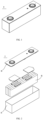
- FIG. 1 is a schematic diagram of a secondary battery 5 of a rectangular structure as an example.
- the outer package may include a casing 51 and a cover plate 53, wherein the casing 51 may include a bottom plate and side plates connected to the bottom plate, and the bottom plate and the side plates are enclosed to form an accommodating cavity.
- the casing 51 has an opening communicating with the accommodating cavity, and the cover plate 53 is used to cover the opening to close the accommodating cavity.
- a positive electrode plate, a negative electrode plate, and a separator may be made into an electrode assembly 52 by a winding process or a laminating process.
- the electrode assembly 52 is packaged in the accommodating cavity.
- the electrolytic solution is infiltrated in the electrode assembly 52.
- the number of electrode assemblies 52 contained in the secondary battery 5 may be one or more, and may be adjusted according to requirements.
- a positive electrode plate, a negative electrode plate, a separator and an electrolytic solution may be assembled into a secondary battery.
- a positive electrode plate, a separator, and a negative electrode plate can be made into an electrode assembly by a winding process or a laminating process, and the electrode assembly can be placed in an outer package and is subjected to drying, to which an electrolytic solution is injected. After vacuum encapsulation, resting, chemical formation, and shaping process, a secondary battery can be obtained.
- the secondary batteries according to the present application can be assembled into a battery module, and the number of secondary batteries contained in the battery module can be more than one, and the specific number can be adjusted according to application and capacity of the battery module.
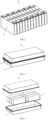
- FIG. 3 is a schematic diagram of the battery module 4 as an example.
- a plurality of secondary batteries 5 may be arranged in sequence along a longitudinal direction of the battery module 4. Certainly, they can also be arranged in any other manner. Furthermore, a plurality of secondary batteries 5 can be fixed with fasteners.
- the battery module 4 may further include a housing having an accommodating space in which a plurality of secondary batteries 5 are accommodated.
- the above-mentioned battery modules can also be assembled into a battery pack, and the number of battery modules included in the battery pack can be adjusted according to the application and capacity of the battery pack.
- FIGS. 4 and 5 are schematic diagrams of the battery pack 1 as an example.
- the battery pack 1 may include a battery case and a plurality of battery modules 4 provided in the battery case.
- the battery case includes an upper case 2 and a lower case 3, and the upper case 2 is used to cover the lower case 3 to form a closed space for accommodating the battery modules 4.
- a plurality of battery modules 4 may be arranged in the battery case in any manner.
- a fourth aspect of the present application provides an electrical device comprising at least one of the secondary battery, battery module, and battery pack of the present application.
- the secondary battery, battery module or battery pack can be used as a power source of the electrical device, and can also be used as an energy storage unit of the electrical device.
- the electrical device can be, but is not limited to, a mobile device (e.g., a mobile phone, a notebook computer, and the like), an electric vehicle (e.g., a pure electric vehicle, a hybrid electric vehicle, a plug-in hybrid electric vehicle, an electric bicycle, an electric scooter, an electric golf vehicle, an electric truck and the like), an electric train, a ship, a satellite, an energy storage system, and the like.
- the electrical device can select a secondary battery, a battery module or a battery pack according to its usage requirements.
- FIG. 6 is a schematic diagrams of an electrical device as an example.
- the electrical device 6 is a pure electric vehicle, a hybrid electric vehicle, or a plug-in hybrid electric vehicle.
- a battery pack 1 or a battery module can be used.
- the electrical device may be a mobile phone, a tablet computer, a notebook computer, and the like.
- the electric device is generally required to be light and thin, and a secondary battery can be used as a power source.
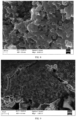
- FIGS. 7 and 8 illustrated cross-sectional views of a porous carbon matrix having a pore structure that exhibits a three-dimensional crosslinked network, and it can also be seen in FIG. 8 that the pore structure presenting a three-dimensional crosslinked network is in a laminar distribution in the carbon-based matrix particles.
- the negative electrode active material (25% silicon-carbon composite prepared above + 75% artificial graphite), conductive carbon black, sodium carboxymethyl cellulose (CMC-Na) as a thickener, and styrene-butadiene rubber emulsion (SBR) as a binder were thoroughly stirred and mixed in an appropriate amount of deionized water at a weight ratio of 96.5: 1.0: 1.0: 1.5 so as to form a homogeneous negative electrode slurry; the negative electrode slurry was applied to a negative electrode collector, followed by drying and other processes, thereby obtaining a negative electrode plate.
- CMC-Na sodium carboxymethyl cellulose
- SBR styrene-butadiene rubber emulsion
- LiNi 0.8 Co 0.1 Mn 0.1 O 2 (NCM811) as a positive active material, polyvinylidene fluoride (PVDF) as a binder, and acetylene black as a conductive agent were dissolved in N-methyl pyrrolidone (NMP) as a solvent at a weight ratio of 97%:1.5%:1.5%, and then were thoroughly stirred and mixed.
- NMP N-methyl pyrrolidone
- the positive electrode slurry was uniformly applied to an aluminium foil as a positive electrode collector, followed by drying, cold pressing, and slitting, thereby obtaining a positive electrode plate.
- ethylene carbonate (EC), ethyl methyl carbonate (EMC), and diethyl carbonate (DEC) were mixed in a ratio of 1:1:1 by volume, and then LiPF 6 was uniformly dissolved in the above solution to obtain an electrolyte solution.
- LiPF 6 has a concentration of 1 mol/L.
- the above-mentioned positive electrode plate, separator, and negative electrode plate were stacked and wound in order to obtain an electrode assembly.
- the electrode assembly was placed into an outer package, to which the electrolytic solution prepared above was added, and then it was subjected to encapsulation, resting, chemical formation, aging, and other processes, thereby obtaining a secondary battery.
- the secondary battery of Comparative Example 1 was prepared in a process that was basically the same as that of Example 1, with the difference that in Comparative Example 1, a different silicon carbon composite material was used and the silicon carbon composite material was prepared as follows:
- FIG. 9 illustrates cross-sectional views of the porous carbon-based matrix particles of Comparative Example 1. As can be seen, it had a honeycomb pore structure.
- Example 1 The parameters of Examples 1-5 and Comparative Example were shown in Table 1: Table 1 No. Pore structure Silicon-carbon mass ratio Cycle life/times Specific capacity of negative electrode active material /mAh/g Example 1 Three-dimensional network interconnecting pore structure 40.1% 1500 1950 Comparative Example 1 honeycomb pore structure 7.3% 400 550
- Example 2-6 the secondary battery was prepared in a process that was basically the same as that of Example 1, with the difference that the process parameters for the preparation of the silicon-carbon composite were adjusted in Examples 2-6, as detailed in Table Table 2 No.
- Crosslinking resin Solvent porogenic agent a1/a2 a1/a3 Preheating temperature (°C) First carbonization temperature (°C) Second carbonization temperature (°C) Type Mass Type Mass Type Mass Example 1 phenolic resin 500g anhydrous ethanol 500g ZnCl 2 250 g 1 2 60 500 1000
- Example 2 phenolic resin 500g anhydrous ethanol 500g ZnCl 2 250 g 1 2 80 500 1000
- Example 3 phenolic resin 500g anhydrous ethanol 500g ZnCl 2 375 g 1 1.3 80 700 1000
- Example 5 phenolic resin 500g anhydrous ethanol 1000g ZnCl 2 500 g 0.5 1
- the secondary battery obtained from each examples and comparative example was charged at a constant current at a rate of 0.5 C to a charge cutoff voltage of 4.25 V at 25°C, and then charged at a constant voltage to a current of ⁇ 0.05 C, it was allowed to set standing for 5 min, and it was discharged at a constant current at a rate of 0.33 C to a discharge cutoff voltage of 2 V, and then it was allowed to set standing for 5 min, which is a charge and discharge cycle.
- the battery was subjected to a cycle charge and discharge test, until capacity of the battery declined to 80%. The number of cycle at this time was cycle life of the battery at 25°C.
- the specific capacity of the negative electrode active material was tested as described below.
- the negative electrode plate prepared in the above Examples and Comparative Example was taken, and then punched and cut into a small disc sample of 1.8 cm 2 ⁇ 1.8 cm 2 , in which the weight of the small disc sample was weighted as M1, and the weight of the current collector in the small disc sample was weighted as M2.
- a lithium metal plate was taken as a counter electrode, and a polyethylene (PE) film was used as a separator, and an electrolytic solution was obtained by mixing ethylene carbonate (EC), ethyl methyl carbonate (EMC), diethyl carbonate (DEC) at a ratio of 1:1:1 by volume, and then dissolving LiPF 6 in the above solution uniformly to obtain the electrolytic solution, in which LiPF6 had a concentration of 1 mol/L.
- EC ethylene carbonate
- EMC ethyl methyl carbonate
- DEC diethyl carbonate
- the carbon-based matrix particles with a three-dimensional network interconnecting pore structure as prepared and obtained by Example 1 can provide more space for silicon, which can be used for the storage of a large amount of silicon, thus improving specific capacity of the silicon-carbon composite.
- such pore structure enables silicon to be dispersed uniformly in pores, and not to be agglomerated easily, and the pore structure can alleviate the volume effect of silicon in the process of intercalation and deintercalation of lithium, and can fully withstand stress changes generated by silicon, thereby ensuring structural stability of the silicon-carbon composite, and thus improving cycle stability of the silicon-carbon composite.
- the pore structure of the carbon-based matrix particles of Comparative Example 1 is a honeycomb pore structure, which is not conducive to providing sufficient space for deposition of silicon, resulting in a relatively low amount of deposited silicon, and the material obtained by compounding silicon and carbon has a relatively small specific capacity. In addition, the material obtained by compounding silicon and carbon has a worse overall structural stability, resulting in a relatively low cycle life when it is applied to a secondary battery.
Landscapes
- Chemical & Material Sciences (AREA)
- Chemical Kinetics & Catalysis (AREA)
- Electrochemistry (AREA)
- General Chemical & Material Sciences (AREA)
- Inorganic Chemistry (AREA)
- Composite Materials (AREA)
- Organic Chemistry (AREA)
- Engineering & Computer Science (AREA)
- Materials Engineering (AREA)
- Manufacturing & Machinery (AREA)
- Battery Electrode And Active Subsutance (AREA)
Applications Claiming Priority (1)
| Application Number | Priority Date | Filing Date | Title |
|---|---|---|---|
| PCT/CN2022/112206 WO2024031667A1 (fr) | 2022-08-12 | 2022-08-12 | Matériau composite de silicium-carbone et son procédé de préparation, et batterie secondaire comprenant un matériau composite de silicium-carbone |
Publications (2)
| Publication Number | Publication Date |
|---|---|
| EP4546455A1 true EP4546455A1 (fr) | 2025-04-30 |
| EP4546455A4 EP4546455A4 (fr) | 2026-01-07 |
Family
ID=89850488
Family Applications (1)
| Application Number | Title | Priority Date | Filing Date |
|---|---|---|---|
| EP22954624.7A Pending EP4546455A4 (fr) | 2022-08-12 | 2022-08-12 | Matériau composite de silicium-carbone et son procédé de préparation, et batterie secondaire comprenant un matériau composite de silicium-carbone |
Country Status (4)
| Country | Link |
|---|---|
| US (1) | US20250038176A1 (fr) |
| EP (1) | EP4546455A4 (fr) |
| CN (1) | CN117882228A (fr) |
| WO (1) | WO2024031667A1 (fr) |
Families Citing this family (4)
| Publication number | Priority date | Publication date | Assignee | Title |
|---|---|---|---|---|
| EP4550450A4 (fr) * | 2022-08-26 | 2025-11-19 | Contemporary Amperex Technology Hong Kong Ltd | Matériau composite silicium-carbone et son procédé de préparation, et accumulateur le comprenant |
| CN118032593B (zh) * | 2024-04-10 | 2024-07-23 | 瑞浦兰钧能源股份有限公司 | 一种颗粒辊压粘结强度的评估方法 |
| CN118458767A (zh) * | 2024-05-07 | 2024-08-09 | 厦门厦钨新能源材料股份有限公司 | 一种利于硅沉积的多孔碳材料和硅碳负极材料及其制备方法和应用 |
| CN121601602A (zh) * | 2024-08-15 | 2026-03-03 | 宁德时代新能源科技股份有限公司 | 电池单体、硅碳复合材料及制备方法、电池装置及用电装置 |
Family Cites Families (8)
| Publication number | Priority date | Publication date | Assignee | Title |
|---|---|---|---|---|
| CN103311523B (zh) * | 2013-06-04 | 2017-02-08 | 清华大学深圳研究生院 | 具有纳米微孔隙的硅碳复合材料及其制备方法与用途 |
| CN106207108B (zh) * | 2016-07-09 | 2018-07-27 | 太原理工大学 | 基于高分子发泡微球的硅碳复合材料及其制备方法与应用 |
| KR102591512B1 (ko) * | 2016-09-30 | 2023-10-23 | 삼성전자주식회사 | 음극 활물질 및 이를 채용한 리튬 이차 전지, 및 상기 음극 활물질의 제조방법 |
| JP2020507547A (ja) * | 2017-02-10 | 2020-03-12 | ワッカー ケミー アクチエンゲゼルシャフトWacker Chemie AG | リチウムイオン電池のアノード材料のためのコア−シェル複合粒子 |
| CN107134567A (zh) * | 2017-04-24 | 2017-09-05 | 广东烛光新能源科技有限公司 | 硅碳负极材料及其制备方法 |
| CN107069010A (zh) * | 2017-04-24 | 2017-08-18 | 广东烛光新能源科技有限公司 | 一种硅碳负极材料及其制备方法 |
| US11984580B2 (en) * | 2019-05-06 | 2024-05-14 | Honeycomb Battery Company | Protected anode active material particles for rechargeable lithium batteries |
| CN113097487B (zh) * | 2021-04-01 | 2022-11-22 | 广东凯金新能源科技股份有限公司 | 一种高度致密结构硅碳复合材料、其制备方法及其应用 |
-
2022
- 2022-08-12 EP EP22954624.7A patent/EP4546455A4/fr active Pending
- 2022-08-12 CN CN202280005715.9A patent/CN117882228A/zh active Pending
- 2022-08-12 WO PCT/CN2022/112206 patent/WO2024031667A1/fr not_active Ceased
-
2024
- 2024-10-13 US US18/914,241 patent/US20250038176A1/en active Pending
Also Published As
| Publication number | Publication date |
|---|---|
| CN117882228A (zh) | 2024-04-12 |
| WO2024031667A1 (fr) | 2024-02-15 |
| US20250038176A1 (en) | 2025-01-30 |
| EP4546455A4 (fr) | 2026-01-07 |
Similar Documents
| Publication | Publication Date | Title |
|---|---|---|
| JP7406625B2 (ja) | 人造黒鉛、二次電池、製造方法及び装置 | |
| CN113207314B (zh) | 二次电池、装置、人造石墨及制备方法 | |
| EP4546455A1 (fr) | Matériau composite de silicium-carbone et son procédé de préparation, et batterie secondaire comprenant un matériau composite de silicium-carbone | |
| JP2026506141A (ja) | 二次電池及び電気装置 | |
| CN118693274B (zh) | 正极活性材料、正极极片、电池及用电装置 | |
| JP7640734B2 (ja) | 負極活物質及びその製造方法、並びに負極活物質を含む装置 | |
| JP7498267B2 (ja) | 球状化カーボン系負極活物質、その製造方法、それを含む負極、及びリチウム二次電池 | |
| KR102834409B1 (ko) | 실리콘-카본 음극 재료, 음극판, 이차 전지, 전지 모듈, 전지 팩 및 전기 장치 | |
| JP2025519408A (ja) | 炭素材料及びその製造方法、並びにそれを用いた二次電池及び電力消費装置 | |
| EP4654281A1 (fr) | Batterie secondaire et dispositif électrique | |
| CN119852482B (zh) | 一种二次电池及用电装置 | |
| JP7752791B2 (ja) | 炭素材料及びその製造方法、並びにそれを含む二次電池及び電力消費装置 | |
| JP2026513003A (ja) | シリコン系負極活物質、二次電池及び電気装置 | |
| CN118661289B (zh) | 二次电池及用电装置 | |
| CN118591903B (zh) | 二次电池及用电装置 | |
| CN119301771B (zh) | 二次电池及用电装置 | |
| EP4693475A1 (fr) | Matériau composite silicium-carbone et son procédé de préparation, batterie secondaire et dispositif électrique | |
| JP7849514B2 (ja) | 炭素材料及びその製造方法、並びにそれを用いた二次電池及び電力消費装置 | |
| JP2025517147A (ja) | 二次電池及び電力消費装置 | |
| EP4654295A1 (fr) | Matériau composite de silicium et procédé de préparation, feuille d'électrode négative, batterie et dispositif électrique | |
| WO2024197887A1 (fr) | Batterie secondaire et dispositif électrique | |
| CN115842111A (zh) | 负极活性材料、包含其的二次电池及用电装置 | |
| CN120073033A (zh) | 一种二次电池及用电装置 | |
| CN119318046A (zh) | 二次电池及用电装置 | |
| CN120829158A (zh) | 碳基材料及其制备方法、二次电池以及用电装置 |
Legal Events
| Date | Code | Title | Description |
|---|---|---|---|
| STAA | Information on the status of an ep patent application or granted ep patent |
Free format text: STATUS: THE INTERNATIONAL PUBLICATION HAS BEEN MADE |
|
| PUAI | Public reference made under article 153(3) epc to a published international application that has entered the european phase |
Free format text: ORIGINAL CODE: 0009012 |
|
| STAA | Information on the status of an ep patent application or granted ep patent |
Free format text: STATUS: REQUEST FOR EXAMINATION WAS MADE |
|
| 17P | Request for examination filed |
Effective date: 20250121 |
|
| AK | Designated contracting states |
Kind code of ref document: A1 Designated state(s): AL AT BE BG CH CY CZ DE DK EE ES FI FR GB GR HR HU IE IS IT LI LT LU LV MC MK MT NL NO PL PT RO RS SE SI SK SM TR |
|
| DAV | Request for validation of the european patent (deleted) | ||
| DAX | Request for extension of the european patent (deleted) | ||
| A4 | Supplementary search report drawn up and despatched |
Effective date: 20251204 |
|
| RIC1 | Information provided on ipc code assigned before grant |
Ipc: H01M 4/36 20060101AFI20251128BHEP Ipc: H01M 10/0525 20100101ALI20251128BHEP |