EP4546584A2 - Support de montage pour composants électriques - Google Patents
Support de montage pour composants électriques Download PDFInfo
- Publication number
- EP4546584A2 EP4546584A2 EP24208519.9A EP24208519A EP4546584A2 EP 4546584 A2 EP4546584 A2 EP 4546584A2 EP 24208519 A EP24208519 A EP 24208519A EP 4546584 A2 EP4546584 A2 EP 4546584A2
- Authority
- EP
- European Patent Office
- Prior art keywords
- support
- rail
- mounting bracket
- support rail
- mounting
- Prior art date
- Legal status (The legal status is an assumption and is not a legal conclusion. Google has not performed a legal analysis and makes no representation as to the accuracy of the status listed.)
- Pending
Links
Images




Classifications
-
- H—ELECTRICITY
- H02—GENERATION; CONVERSION OR DISTRIBUTION OF ELECTRIC POWER
- H02G—INSTALLATION OF ELECTRIC CABLES OR LINES, OR OF COMBINED OPTICAL AND ELECTRIC CABLES OR LINES
- H02G3/00—Installations of electric cables or lines or protective tubing therefor in or on buildings, equivalent structures or vehicles
- H02G3/02—Details
- H02G3/08—Distribution boxes; Connection or junction boxes
- H02G3/12—Distribution boxes; Connection or junction boxes for flush mounting
- H02G3/123—Distribution boxes; Connection or junction boxes for flush mounting in thin walls
- H02G3/125—Distribution boxes; Connection or junction boxes for flush mounting in thin walls with supporting bar extending between two separate studs of a wall frame
-
- H—ELECTRICITY
- H02—GENERATION; CONVERSION OR DISTRIBUTION OF ELECTRIC POWER
- H02G—INSTALLATION OF ELECTRIC CABLES OR LINES, OR OF COMBINED OPTICAL AND ELECTRIC CABLES OR LINES
- H02G3/00—Installations of electric cables or lines or protective tubing therefor in or on buildings, equivalent structures or vehicles
- H02G3/02—Details
- H02G3/08—Distribution boxes; Connection or junction boxes
- H02G3/081—Bases, casings or covers
-
- H—ELECTRICITY
- H02—GENERATION; CONVERSION OR DISTRIBUTION OF ELECTRIC POWER
- H02G—INSTALLATION OF ELECTRIC CABLES OR LINES, OR OF COMBINED OPTICAL AND ELECTRIC CABLES OR LINES
- H02G3/00—Installations of electric cables or lines or protective tubing therefor in or on buildings, equivalent structures or vehicles
- H02G3/02—Details
- H02G3/08—Distribution boxes; Connection or junction boxes
- H02G3/10—Distribution boxes; Connection or junction boxes for surface mounting on a wall
- H02G3/105—Distribution boxes; Connection or junction boxes for surface mounting on a wall in association with a plinth, channel, raceway or similar
-
- H—ELECTRICITY
- H02—GENERATION; CONVERSION OR DISTRIBUTION OF ELECTRIC POWER
- H02G—INSTALLATION OF ELECTRIC CABLES OR LINES, OR OF COMBINED OPTICAL AND ELECTRIC CABLES OR LINES
- H02G3/00—Installations of electric cables or lines or protective tubing therefor in or on buildings, equivalent structures or vehicles
- H02G3/26—Installations of cables, lines, or separate protective tubing therefor directly on or in walls, ceilings, or floors
- H02G3/263—Installation, e.g. suspension, of conduit channels or other supports
Definitions
- electrical equipment e.g., conduit, boxes, fittings, and other components
- structural members e.g., wall studs
- electrical equipment may be required to be supported at particular heights above a floor or at particular distances from certain other structures or components.
- the electrical assembly may include a mounting bracket that may include support rails, including a first support rail and a second support rail slidably received within the first support rail.
- the first support rail may include a first rail guide and a second rail guide, and a first recessed channel extending into a front side of the first support rail between the first rail guide and the second rail guide.
- the second support rail may include a third rail guide nested within the first rail guide and a fourth rail guide nested within the second rail guide, and a second recessed channel extending into a front side of the second support rail between the third rail guide and the fourth rail guide, with the first recessed channel nested within the second recessed channel.
- the electrical assembly may include an electrical box may having a rear wall. The electrical box may be secured at the front side of the first support rail with the rear wall of the electrical box deformed into the first and second recessed channels.
- the mounting bracket may include a first support rail with a first recessed channel and a second support rail with a second recessed channel.
- the first and second support rails may be nested together for telescopic adjustment along a lateral direction, with the first recessed channel nested within the second recessed channel.
- One of the first support rail or the second support rail may have centering tabs that extend to biasingly engage the other of the first or second support rails to maintain alignment of the first and second support rails with respect to each other, transverse to the lateral direction.
- the mounting bracket may include a first support rail with a first recessed channel and a second support rail with a second recessed channel.
- the first and second support rails may be nested together for telescopic adjustment along a lateral direction, with the first recessed channel nested within the second recessed channel.
- the first recessed channel can be nested within the second recessed channel to receive a rear wall of the electrical box into the first and second recessed channels to secure the electrical box against rotation (e.g., as deformed into the first and second recessed channels by a fastener that extends through the rear wall in alignment with the first and second recessed channels).
- a gap may be defined between the first and second support rails transverse to the lateral direction, with the centering tabs providing the only points of contact between the first and second support rails across the gap.
- the centering tabs may bridge the gap to slidably engage the other of the first or second support rails.
- the first support rail may include a first rail guide and a second rail guide, and the first recessed channel may extend between the first rail guide and the second rail guide.
- the second support rail may include a third rail guide nested within the first rail guide and a fourth rail guide nested within the second rail guide, and the second recessed channel may extend between the third rail guide and the fourth rail guide.
- the first and second rail guides may include the centering tabs extending toward the third and fourth rail guides, respectively. At least one of the centering tabs may extend from the first rail guide to bear against the third rail guide and at least one of the centering tabs may extend from the second rail guide to bear against the fourth rail guide to bias the first and second support rails toward a centered orientation.
- the centering tabs may be integrally formed with the first support rail.
- the first recessed channel may include a first rear wall
- the second recessed channel may include a second rear wall
- mounting holes may be arrayed along the first and second rear walls.
- the mounting holes of the first and second recessed channels may be selectively alignable by telescopic movement of the first and second support rails to cooperatively receive fasteners that secure electrical components to the mounting bracket.
- a structure mount may extend in a respective distal direction from a distal end of each of the first and second support rails to secure the mounting bracket to a corresponding support structure.
- each of the structure mounts may include sets of reliefs at which the structure mounts may be bendable to set an offset of the corresponding first or second support rail from a front face of the corresponding structural support.
- the reliefs may define bend lines, the bend lines corresponding to predetermined mounting distances from a front face of a first of the adjacent structural supports.
- Some examples provide an electrical assembly comprising a mounting bracket as described above and an electrical box having a rear wall and being secured at a front side of the first support rail with the rear wall of the electrical box deformed into the first and second recessed channels to secure the electrical box at the front side of the first support rail.
- the rear wall of the electrical box may be deformed into the first and second recessed channels by one or more fasteners that extend through one or more aligned set of the first and second support rail mounting holes to secure the electrical box to the mounting bracket.
- the method may include telescopically adjusting a mounting bracket in a lateral direction, with a first recessed channel of a first support rail of the mounting bracket slidably nested within a second recessed channel of a second support rail of the mounting bracket.
- the method may include securing the telescopically adjusted mounting bracket to a building structure, with the first support rail secured to a first structural support and the second support rail secured to a second structural support.
- the method may include fastening an electrical component to the first and second support rails with a fastener so that the fastener deforms the electrical component into the first recessed channel to resist rotation of the electrical component relative to the mounting bracket.
- centering tabs of the first or second support rail may biasingly engage the other of the first or second support rail to maintain alignment of the first and second support rails with respect to each other, transverse to the lateral direction.
- the electrical component may be an electrical box, and a rear wall of the electrical box may be deformed by multiple fasteners into the first and second recessed channels.
- securing the first support rail to the first structural support may include bending the first support rail to extend a structure mount of the first support rail in a first direction along the first structural support, with a mounting tab extending from the structure mount in a second direction along the first structural support, and securing the structure mount to the first structural support.
- the first structural mount may be a building stud, and securing the first support rail to the first structural support may further include inserting a fastener through the mounting tab to engage a closed side of the building stud.
- electrical components e.g., conduit or electrical components
- structural members e.g., wall studs
- examples of the disclosed technology can be useful for this purpose, and others.
- examples of the disclosed technology can be used to support one or more of electrical conduits, electrical junction boxes, or other electrical components on a mounting bracket at a configurable distance away from structural members (e.g., in a space between adjacent studs).
- Some examples can additionally (or alternatively) include structures for improved engagement between a mounting bracket and a supported electrical component.
- a mounting bracket can include a first support rail with a recessed channel in a mounting section.
- the recessed channel in some cases, can be configured to be received and translatable within a corresponding recessed channel in a mounting section of a second support rail.
- the recessed channels of the first and second support rail can define a respective space between a contact surface of the mounting bracket and a rear wall of the recessed channel.
- a mounting bracket can have a plurality of centering tabs extending inward from a first rail guide and a second rail guide of the first support rail configured to contact the corresponding first and second rail guide of the second support rail to center the second support rail within the first support rail.
- the plurality of centering tabs may extend outward from the first rail guide and the second rail guide of the second support rail configured to contact the corresponding first and second rail guide of the first support rail to center the second support rail within the first support rail.
- a mounting bracket can include a mounting tab on the structure mounts of the first and second support rails configured to receive a fastener to secure the mounting bracket to a closed side of a structural member (e.g., at a location that is closer to a support plane defined by rails of the mounting bracket than to a front plane of a stud to which the mounting bracket is attached).
- an electrical box is secured to a flat mounting surface of a mounting bracket with a fastener extending through a hole in the back wall of the electrical box into a hole in the flat mounting surface.
- the fastener may not be capable of providing a quality securement of the electrical box to the mounting bracket because, for example, the face-to-face arrangement of the back wall of the electrical box and the flat mounting surface of the mounting bracket does not allow the threads of the fastener (e.g., a lack of threads adjacent the head of the fastener) to engage adequately with the hole in the flat mounting surface. This can lead to a loose electrical box mounting, for example, if the box is bumped or twisted because the limited thread engagement with the hole in the flat mounting surface is less stable.
- the disclosed technology can address this issue, or others.
- some examples of the disclosed technology are presented below in the context of mounting brackets for electrical components, wherein the mounting brackets have recessed channels that are configured to space a rear wall of the channels from a contact surface of the mounting bracket.
- the contact surface contacts, for example, a back wall of an electrical box to support the electrical box in a mounted configuration.
- the spaced arrangement of the rear wall of the channel can allow for threads of the fastener to engage more fully with a hole in the rear wall of the recessed channel.
- securing the fastener can induce a locking force by deformation of the back wall of the electrical box and thereby further encourage engagement of the threads of the fastener with the rear wall of the mounting bracket and resist rotation of the box relative to the bracket.
- between-stud brackets are presented in particular.
- the principles disclosed herein can be used with any variety of mounting brackets, including stud-mounted brackets, floor-supported brackets, between-stud brackets, and so on, and can be used to secure any variety of components in place (e.g., electrical boxes or other electrical assemblies or devices).
- examples of a mounting bracket as presented below can be readily formed as an integral stamping, with mechanical or other (e.g., welded, fastened, adhesive-based, etc.) attachment of other components, as needed.
- mechanical or other e.g., welded, fastened, adhesive-based, etc.
- other manufacturing techniques including extrusion, additive manufacturing, casting, and so on.
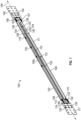
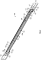
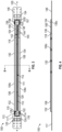
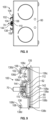
- FIGS. 1 through 6 illustrate an example of a mounting bracket 100 configured to be mounted to adjacent structural members (e.g., extend horizontally between and be secured to structural supports such as wall framing studs, e.g., wall studs 50 shown in FIG. 10 ) and to support electrical components (e.g., an electrical junction box 60 shown in FIGS. 7 through 9 ).
- the mounting bracket 100 is formed as a stamping from a single blank of material (e.g., 23 gauge mild steel), although a variety of other approaches are possible.
- the mounting bracket 100 includes a first support rail 102 and a second support rail 104.
- the second support rail 104 is configured to be slidably received within and slidably movable with respect to the first support rail 102.
- the first support rail 102 may be slidably adjustable relative to the second support rail 104 along an adjustment axis 105 in a first direction, and a second direction opposite the first direction, to adjust an extension of the mounting bracket 100.
- the first support rail 102 contains features for attaching to a structural support (see e.g., wall stud 50 in FIG. 10 ) and also engagement with the second support rail 104.
- the first support rail 102 includes a first rail guide 106, a second rail guide 108, and a rear wall 110 that connects the first and second rail guides 106, 108.
- a mounting section 111 may extend between the first and second rail guides 106, 108 (e.g., forming an inner portion of each of the first and second rail guides 106, 108, as shown).
- the mounting section 111 may secure the electrical junction box 60 to the mounting bracket 100, e.g., with the electrical junction box 60 seated in contact with the mounting section 111 (as shown in FIG. 9 ).
- the first rail guide 106 of the first support rail 102 extends from the rear wall 110.
- the first rail guide 106 may generally define a C-shaped cross-sectional shape (i.e., a shape that extends to enclose a central space at at least three sides thereof, while leaving an opening along at least one side of the central space for lateral entry thereto).
- the first rail guide 106 may include a first support section 106a extending from the rear wall 110 in a third direction (e.g., a forward direction) that is substantially perpendicular to the first direction and to the rear wall 110.
- the first rail guide 106 may further include a second support section 106b extending substantially perpendicular to the first support section 106a, and extending substantially parallel to the rear wall 110.
- a third support section 106c may extend from the second support section 106b, opposite the first support section 106a, in a fourth direction (e.g., a rearward direction), that is opposite the third direction.
- a fourth support section 106d may extend from the third support section 106c, opposite the second support section 106b, in a direction that is substantially parallel to the second support section 106b and toward the first support section 106a.
- the second rail guide 108 extends from the rear wall 110, opposite the first rail guide 106.
- the second rail guide 108 may generally define a C-shaped cross-sectional shape.
- the second rail guide 108 may include a fifth support section 108a extending from the rear wall 110 in the third direction.
- the second rail guide 108 may further include a sixth support section 108b extending substantially perpendicular to the fifth support section 108a, and extending substantially parallel to the rear wall 110.
- a seventh support section 108c may extend from the sixth support section 108b, opposite the fifth support section 108a, in the fourth direction.
- an eighth support section 108d may extend from the seventh support section 108c, opposite the sixth support section 108b, in a direction that is substantially parallel to the sixth support section 108b and toward the fifth support section 108a.
- the cross-sectional shape of the first or second rail guides 106, 108 may be consistent along an entire length of the first or second rail guides 106, 108. In other examples, the cross-sectional shape of the first or second rail guides 106, 108 may be consistent along at least 50% the length of the first or second rail guide 106, 108. As described above, an angle between the first and second support section 106a, 106b, the second and third support section 106b, 106c, and the third and fourth support section 106c, 106d, may me about 90 degrees to provide for easy adjustability and notable structural rigidity.
- the angle between the first and second support section 106a, 106b, or the second and third support section 106b, 106c, or the third and fourth support section 106c, 106d may be oblique.
- the angle between adjacent support sections 108a-d of the second rail guide 108 may be about 90 degrees, or may be oblique.
- the mounting section 111 may include one or more of the first and second support sections 106a, 106b and the fifth and sixth support sections 108a, 108b. As described further below, any of the first, second, fifth, and sixth support sections 106a, 106b, 108a, 108b may contact and secure the electrical junction box 60 to the mounting bracket 100 (as shown in FIG. 9 ).
- a recessed channel 112 may be defined by (or between) the rail guides 106, 108 and by the rear wall 110 of the mounting section 111.
- the recessed channel 112 may extend from the rear wall 110 to a front side of the of the first and second rail guides 106, 108.
- the recessed channel 112 may extend from the rear wall 110 to the second and sixth support sections 106b, 108b opposite the rear wall 110.
- the recessed channel 112 may further extend between the first and second rail guides 106, 108.
- the recessed channel 112 may be defined between the first and fifth support sections 106a, 108a.
- first support rail mounting holes 120 are spaced apart along at least a portion of the rear wall 110 of the recessed channel 112.
- the first support rail mounting holes 120 are equidistantly spaced along the rear wall 110.
- adjacent first support rail mounting holes 120 may be spaced apart by a first spacing.
- each set of adjacent first support rail mounting holes 120 may be spaced apart by the first spacing.
- the plurality of first support rail mounting holes 120 are configured to receive known types of fasteners (e.g., screws 74 shown in FIGS. 7 through 9 ) to secure electrical components (e.g., the electrical junction box 60 shown in FIGS. 7 through 9 ) to the mounting section 111.
- the first and second rail guides 106, 108 may extend in the first direction from a free end section 118 (e.g., a proximal end), to a distal end.
- the first support rail 102 may include a structure mount 117 that extends from the first and second rail guides 106, 108. Specifically, the first support rail 102 extends from the distal end of the first and second rail guides 106, 108 in the first direction (e.g., a distal direction) to an end of the first support rail 102, opposite the free end section 118.
- the structure mount 117 may be a flange.
- the structure mount 117 may be a planar (or other) extension that is bendable to secure the first support rail 102 to a structural member at a variety of depths (e.g., the wall stud 50 as shown in FIG. 10 ).
- the structural mount 117 may generally be rectangular.
- the structural mount 117 may instead be circular, triangular, or any other relevant shape, and may further be rigid, partially rigid, or otherwise define relevant material properties.
- the structure mount 117 may be connected to the first and second rail guides 106, 108 by one or more legs.
- a first leg 113 may extend from the second support section 106b of the first rail guide 106
- a second leg 114 may extend from the sixth support section 108b of the second rail guide 108, spaced apart from the first leg 113, to connect the structure mount 117 to the rail guides 106, 108.
- an embossment 116 may extend along the first and second legs 113, 114 to provide rigidity and structural integrity to the connection between the rail guides 106, 108 and the structure mount 117.
- the legs 113, 114 may be bent to allow the structure mount 117 to extend away from (e.g., substantially perpendicular to) the rail guides 106, 108, and thereby to ease securement of the structure mount 117 to the wall stud 50 (e.g., to a closed side 54, as shown in FIG. 11 ).
- use of two legs e.g., with reinforcement as shown
- a mounting tab 122 extends from the structure mount 117 in the second direction, toward the rail guides 106, 108.
- the mounting tab 122 may extend from the structure mount 117 through a gap 115 between the legs 113, 114.
- a first section of the embossment 116 may extend along the first leg 113 and a second section of the embossment 116 may extend along the second leg 114.
- the first and second sections of the embossment 116 may be connected, such that the embossment 116 partially encompasses the gap 115, and therefore the mounting tab 122, to provide rigidity and strength to the structure mount 117.
- the mounting tab 122 may be configured to receive a fastener to secure the structure mount 117, and thus the first support rail 102, to one of the wall studs 50.
- the structure mount 117 includes a plurality of sets of reliefs 124 about which an installer can bend the structure mount 117.
- the structure mount 117 can be adjusted to be set back the mounting section 111 from a face 52 of the wall stud 50 at a variety of predetermined distances, e.g., depending on the in-wall spacing required to mount a specific mechanical component to the mounting bracket 100.
- the reliefs 124 can be linearly arrayed to define corresponding bend lines 125.
- the reliefs 124 may include a continuous score line or a discontinuous score line (e.g., a dashed score line or the like) that provide a weakened groove in the structure mount 117 along the bend lines 125.
- the reliefs 124 may include one or more holes disposed along the bend lines 125, including circular holes, oblong holes, holes of various diameters, lengths, and sizes, as well as holes defining other relevant shapes.
- the reliefs 124 can include U-shaped cut-outs disposed at either end of the bend line 125.
- the reliefs 124 may otherwise include areas of weakened material that can be disposed along the bend lines 125 to ease manual (or other) adjustment of the structure mount 117.
- the structure mount 117 includes the plurality of sets of reliefs 124 that allow an installer to bend the structure mount 117 at a variety of predetermined locations based on a size of a desired mechanical component.
- the bend lines 125 defined by the reliefs 124 may correspond to a predetermined mounting distance from a front face of the wall stud 50 (e.g., a mounting distance between the front face of the wall studs 50 and the mounting section 111 of the first rail 104) (as shown in FIG. 11 ).
- the structure mount 117 can be bent at the bend line 125 of one set of the plurality of sets of reliefs 124 to mount an electrical box of a first depth, and the structure mount 117 can be bent at another set of the reliefs 124 to mount an electrical box of a second, different depth.
- one set of the plurality of sets of reliefs 124 can be provided at a location on the structure mount 117 to locate the mounting section 111 in the middle of the depth of the wall stud 50.
- a set of the plurality of sets of reliefs 124 can be provided at a location on the structure mount 117 to place the mounting section 111 flush with the face of the wall stud 50.
- other structure mounts can be included, including mounts that include any variety of known structures to secure a bracket to a stud or other building member.
- an installer may bend the structure mount 117 to set back the mounting section 111 from the face of the wall stud 50 (e.g., at one of the bend lines 125, and at the connection between the legs 113, 114 and the rail guides 106, 108, as shown in FIG. 11 ).
- the installer may secure the structure mount 117 to the face of the wall stud 50 with a fastener received through a hole in the structure mount 117.
- the fastener may be received through one of the relief features 154 or may be received through a dedicated fastener opening.
- the installer can secure the structure mount 117 to a face of the closed side 54 of the wall stud 50 with a fastener received through a hole 126 in the mounting tab 122.
- the mounting tab 122 extends from the structure mount 117 back toward the rail guides 106, 108.
- the tab 122 and any corresponding fastener can provide a securement to the wall stud 50 that is spaced apart from a front of a stud and, correspondingly, more closely aligned with the rails 102, 104.
- securement of the structure mount 117 close to the first and second rail guides 106, 108 can add rigidity to the securement and removes the potential for twisting of the mounting bracket 100.
- the first rail guide 106 may include a first plurality of centering tabs 130 that extend from a top and bottom side of the first support rail 102.
- the first plurality of centering tabs 130 may extend integrally from the first rail guide 106 in an inward direction, specifically in a direction toward the second rail guide 108 or the recessed channel 112.
- the first plurality of centering tabs 130 may extend from the third support section 106c of the first rail guide 106 toward the second rail guide 108.
- the second rail guide 108 may include a second plurality of centering tabs 134 extending inward from the second rail guide 108, specifically in a direction toward the first rail guide 106 or the recessed channel 112.
- the second plurality of centering tabs 134 may extend from the seventh support section 108c of the second rail guide 108 toward the first rail guide 106.
- one or both sets of the centering tabs 130, 134 may bear against the second support rail 104 to bias the second support rail 104 toward a centered orientation (e.g., to be centered relative to an elongate centerline of the first support rail 102). Furthermore, the centering tabs 130, 134 may maintain a gap 135 between first support rail 102 and the second support rail 104, bridging the gap 135 to slidably engage the second support rail 104. In some examples, the centering tabs may provide the only points of contact between the first and second support rails 102, 104 and. correspondingly, the only structure that extends across the gap 135. In some examples, centering tabs can be alternately or additionally positioned at other locations with similar effect (e.g., can extend from the second support rail 104 to biasingly engage the first support rail 102).
- the first support rail 102 and the second support rail 104 may generally include similar features, albeit with difference sizes in some cases to allow for telescopic nesting and movement, as further detailed below.
- the second support rail 104 may generally include similar components to the first support rail 104 including but not limited to a third rail guide 136, including first, second, third, and fourth support sections 136a-d, a fourth rail guide 138, including fifth, sixth, seventh, and eight support sections 138a-d, a rear wall 144, a recessed channel 142 defined by the rear wall 144 and the rail guides 136, 138, a free end section 148, a structure mount 146, including legs 156, 157, a mounting tab 150 and a plurality of reliefs 154, and a plurality of second support rail mounting holes 152 equidistantly spaced along the rear wall 144, including with a second spacing between adjacent second support rail mounting holes 152.
- a third rail guide 136 including first, second, third, and fourth support sections
- first support rail 102 and the second support rail 104 may differ.
- a cross-sectional profile or shape may be alternately sized or shaped to allow the first support rail 102 to nestably receive and partially encompass the second support rail 104.
- the free end section 148 of the second support rail 104 is inserted into the free end section 118 of the first support rail 102.
- the third rail guide 136 may be nested within the first rail guide 106
- the fourth rail guide 138 may be nested within the second rail guide 108
- the recessed channel 142 may be nested within the recessed channel 112.
- the second support rail 104 can then be slidably moved within the first support rail 102, whereby the recessed channel 112 of the first support rail 102 is matingly received within the recessed channel 142 of the second support rail 104, with the rear wall 110 of the mounting section 140 of the second support rail 104 adjacent the rear wall 110 of the mounting section 111 of the first support rail 102.
- the first support rail 104 may then be slidably moved relative to the second support rail 104 to adjust an extension of the mounting bracket 100 to secure the mounting bracket 100 to adjacent wall studs 50 that are offset from one another by a variety of different distances.
- first and second pluralities of centering tabs 130, 134 are configured to contact the second support rail 104 and center the second support rail 104 within the first support rail 102.
- the first and second pluralities of centering tabs 130, 134 are flexible to allow for variations of dimensions along the length of the second support rail 104 to provide a consistent fit between the first and second support rails 102, 104.
- the first and second pluralities of centering tabs 130, 134 center the recessed channel 142 of the second support rail 102 within the recessed channel 112 of the first support rail 102 and define the spacing or gap 135 (shown in FIG.
- first and second support rails 102, 104 to allow for relative translational movement therebetween with minimal points of contact (i.e., resistance).
- the maintained contact between the first and second support rails 102, 104 along a vertical direction - i.e., across the spacing or gap 135 from top to bottom or vice versa, as installed on a vertical stud - can be provided in some case only by the first and second pluralities of centering tabs 130, 134.
- This arrangement can reduce looseness between the support rails 102, 104 while also decreasing the potential for binding due to the support rails 102, 104 twisting relative to each other or due to excess frictional engagement between the rails 102, 104.
- the third rail guide 136 may include a third plurality of centering tabs extending outward from the third rail guide 136 in a direction that is away from the fourth rail guide 138. Specifically, the third plurality of centering tabs may extend from the third support section 106c of the third rail guide 106 toward the first support section 106a. Furthermore, the fourth rail guide 138 may include a fourth plurality of centering tabs extending outward from the fourth rail guide 138 in a direction away of the third rail guide 136. Specifically, the fourth plurality of centering tabs may extend from the seventh support section 108c of the fourth rail guide 108 toward the fifth support section 108a.
- the centering tabs may bear against the first support rail 102 to bias the second support rail 104 toward a centered orientation. Furthermore, the centering tabs may maintain the gap 135 between first support rail 102 and the second support rail 104, bridging the gap 135 to slidably engage the first support rail 102.
- devices or systems disclosed herein can be utilized or installed using methods embodying aspects of the disclosed technology.
- description herein of particular features or capabilities of a device or system is generally intended to inherently include disclosure of a method of using such features for intended purposes and of implementing such capabilities.
- express discussion of any method of using a particular device or system, unless otherwise indicated or limited, is intended to inherently include disclosure, as examples of the disclosed technology, of the utilized features and implemented capabilities of such device or system.
- some examples can include an installation method under which a user can install the mounting bracket 100.
- the method can include, adjusting an extension of the mounting bracket 100 by sliding the first support rail 102 relative to the second support rail 104.
- An extension of the mounting bracket 100 may be adjusted to align the support rails 102, 104 relative to an adjacent set of the walls studs 50.
- the support rails 102, 104 may be adjusted to selectively align one or more of the first support rail mounting holes 120 with one or more of the second support rail mounting holes 152.
- the structure mounts 117, 146 of the support rails 102, 104 may be bent at the legs 113, 114, 156, 157 and may further be selectively bent at a set of the reliefs 124, 154.
- a user may choose to selectively bend the structure mounts 117, 146 at one or more sets of the reliefs 124, 154 to determine an offset distance between the corresponding first or second support rail 102, 104 and a front face 52 of the corresponding wall studs 50.
- the structure mounts 117, 146 may be coupled to the front face 52 of the wall studs 50 by the fasteners 70 extending through one or more of the reliefs 124, or to the closed side 54 of the wall studs 50 by the fasteners 72 extending through the mounting tabs 122, 150.
- some examples can include an installation method under which a user can install an electrical junction box (e.g., the electrical junction box 60) to the mounting bracket 100.
- an electrical junction box e.g., the electrical junction box 60
- the mounting bracket 100 secured to and extending between adjacent wall studs (e.g., the wall studs 50 shown in FIG.
- the method can include placing a back wall 62 of the electrical junction box 60 against at least one of the mounting section 111 of the first support rail 102 or the mounting section 140 of the second support rail 104, aligning holes 64 in the back wall 62 of electrical junction box 60 with at least corresponding holes of the plurality of first support rail mounting holes 120 in the rear wall 110 of the recessed channel 112 of the first support rail 102 or holes of the plurality of second support rail mounting holes 152 in the rear wall 110 of the recessed channel 142 of the second support rail 104; inserting fasteners (e.g., screws 74) through the corresponding holes; and tightening the screws 74.
- fasteners e.g., screws 74
- a single fastener or single line of fasteners can be extended through a corresponding single one of the mounting hole 120 or line of the mounting holes 120, in particular at a vertically centered location within the electrical junction box 60.
- the presently disclosed technology's improved stability relative to rotation can be particularly beneficial in this arrangement. In other examples, however, other arrangements of one or more fasteners are possible.
- the mounting bracket 100 may advantageously be configured to partially deform a wall of the junction box 60 during installation. This deformation can help to better secure the junction box 60 to the mounting bracket 100 by preventing rotation and wobble of the junction box 60 relative to the mounting bracket 100. For example, in some installations tightening the screws 74 that extend through the back wall 62 of the junction box 60 and an aligned set of the support rail mounting holes 120, 152 can partially deform the junction box 60 against the first and second support rails 102, 104.
- a portion of the back wall 62 of the junction box 60 can deform to the shape of the recessed channels 112, 142 of the respective first or second support rail 102, 104, such that the portion of the back wall 62 extends into one or both of the recessed channels 112, 142.
- the back wall 62 is shown as deforming to the profile shape of the recessed channel 112 of the first support rail 102.
- the back wall 62 may be deformed to engage the second and sixth support sections 106b, 108b of the rail guides 106, 108 of the first support rail 102, or to otherwise extend into the recessed channel 112 and the recessed channel 142.
- the deformed material of the electrical junction box 60 may engage the first support rail 104 and prevent movement (e.g., twisting or up or down movement) or loosening of the electrical junction box 60 relative to the mounting bracket 100. In some cases
- the junction box 60 may be coupled to one of the first and second support rails 102, 104 (e.g., but not the other rail 102, 104). Accordingly, the back wall 62 of the junction box 60 may in some cases deform to the profile shape of the recessed channel 112 of the first support rail 102 or the profile shape of the recessed channel 142 of the second support rail 104 (e.g., but not to profile shape of the other recessed channel 112, 142).
- the disclosed technology can provide improved electrical assemblies, including to support electrical boxes or other components relative to studs or other building structures.
- ease and security of installation can be improved in particular, including through intentional deformation of a secured component into a recessed channel or a mounting bracket, or through improved adjustability and structural integrity of a mounting bracket for particular installations.
- directional terms are presented only with regard to the particular example and perspective described.
- reference to features or directions as “horizontal,” “vertical,” “front,” “rear,” “left,” “right,” “upper,” “lower,” and so on are generally made with reference to a particular figure or example and are not necessarily indicative of an absolute orientation or direction.
- relative directional terms for a particular example may generally apply to alternative orientations of that example.
- “front” and “rear” directions or features may be generally understood to indicate relatively opposite directions or features for a particular example, regardless of the absolute orientation of the example (or relative orientation relative to environmental structures).
- “Lateral” and derivatives thereof generally indicate directions that are generally perpendicular to a vertical direction for a relevant reference frame.
- ordinal numbers are used for convenience of presentation only and are generally presented in an order that corresponds to the order in which particular features are introduced in the relevant discussion. Accordingly, for example, a "first" feature may not necessarily have any required structural or sequential relationship to a "second" feature, and so on. Further, similar features may be referred to in different portions of the discussion by different ordinal numbers. For example, a particular feature may be referred to in some discussion as a "first" feature, while a similar or substantially identical feature may be referred to in other discussion as a "third" feature, and so on.
- the term "or” as used herein is intended to indicate exclusive alternatives only when preceded by terms of exclusivity, such as "either,” “one of,” “only one of,” or “exactly one of.”
- a list of "one of A, B, or C” indicates options of: A, but not B and C; B, but not A and C; and C, but not A and B.
- a list preceded by "one or more” (and variations thereon) and including “or” to separate listed elements indicates options of one or more of any or all of the listed elements.
- the phrases "one or more of A, B, or C” and "at least one of A, B, or C” indicate options of: one or more A; one or more B; one or more C; one or more A and one or more B; one or more B and one or more C; one or more A and one or more C; and one or more of A, one or more of B, and one or more of C.
- a list preceded by "a plurality of' (and variations thereon) and including “or” to separate listed elements indicates options of multiple instances of any or all of the listed elements.
- the phrases “a plurality of A, B, or C” and "two or more of A, B, or C” indicate options of: A and B; B and C; A and C; and A, B, and C.
- substantially identical indicates that features or components are manufactured using the same processes according to the same design and the same specifications. In some cases, substantially identical features can be geometrically congruent.
- integral and derivatives thereof (e.g., “integrally") describe elements that are manufactured as a single piece without fasteners, adhesive, or the like to secure separate components together.
- an element stamped, cast, or otherwise molded as a single-piece component from a single piece of sheet metal or using a single mold, without rivets, screws, or adhesive to hold separately formed pieces together is an integral (and integrally formed) element.
- an element formed from multiple pieces that are separately formed initially then later connected together is not an integral (or integrally formed) element.
- substantially parallel indicates a direction that is within ⁇ 12 degrees of a reference direction (e.g., within ⁇ 6 degrees or ⁇ 3 degrees), inclusive.
- substantially perpendicular similarly indicates a direction that is within ⁇ 12 degrees of perpendicular a reference direction (e.g., within ⁇ 6 degrees or ⁇ 3 degrees), inclusive.
- substantially vertical indicates a direction that is substantially parallel to the vertical direction, as defined relative to the reference system (e.g., a local direction of gravity, by default), with a similarly derived meaning for "substantially horizontal” (relative to the horizontal direction). Discussion of directions "transverse” to a reference direction indicate directions that are not substantially parallel to the reference direction. Correspondingly, some transverse directions may be perpendicular or substantially perpendicular to the relevant reference direction
- devices or systems disclosed herein can be utilized, manufactured, or installed using methods embodying aspects of the disclosed technology.
- any description herein of particular features, capabilities, or intended purposes of a device or system is generally intended to include disclosure of a method of using such devices for the intended purposes, of a method of otherwise implementing such capabilities, of a method of manufacturing relevant components of such a device or system (or the device or system as a whole), and of a method of installing disclosed (or otherwise known) components to support such purposes or capabilities.
- discussion herein of any method of manufacturing or using for a particular device or system, including installing the device or system is intended to inherently include disclosure, as examples of the disclosed technology, of the utilized features and implemented capabilities of such device or system.
Landscapes
- Engineering & Computer Science (AREA)
- Architecture (AREA)
- Civil Engineering (AREA)
- Structural Engineering (AREA)
- Casings For Electric Apparatus (AREA)
- Mounting Components In General For Electric Apparatus (AREA)
Applications Claiming Priority (1)
| Application Number | Priority Date | Filing Date | Title |
|---|---|---|---|
| US202363592786P | 2023-10-24 | 2023-10-24 |
Publications (2)
| Publication Number | Publication Date |
|---|---|
| EP4546584A2 true EP4546584A2 (fr) | 2025-04-30 |
| EP4546584A3 EP4546584A3 (fr) | 2025-07-09 |
Family
ID=93283708
Family Applications (1)
| Application Number | Title | Priority Date | Filing Date |
|---|---|---|---|
| EP24208519.9A Pending EP4546584A3 (fr) | 2023-10-24 | 2024-10-24 | Support de montage pour composants électriques |
Country Status (2)
| Country | Link |
|---|---|
| US (1) | US20250132548A1 (fr) |
| EP (1) | EP4546584A3 (fr) |
Family Cites Families (9)
| Publication number | Priority date | Publication date | Assignee | Title |
|---|---|---|---|---|
| US2658241A (en) * | 1950-07-10 | 1953-11-10 | Jr Dale B Houghton | Bridging |
| US4967990A (en) * | 1989-01-26 | 1990-11-06 | B-Line Systems, Inc. | Support for an electrical box |
| US5934631A (en) * | 1996-08-19 | 1999-08-10 | Thomas & Betts Corporation | Hanger bar assembly |
| US6484979B1 (en) * | 2000-07-21 | 2002-11-26 | Lewis B. Medlin, Jr. | Adjustable electrical box support |
| US9696021B2 (en) * | 2004-03-25 | 2017-07-04 | Cooper Technologies Company | Hanger bar for recessed luminaires |
| US7673841B2 (en) * | 2004-03-25 | 2010-03-09 | Cooper Technologies Company | Hangar bar for recessed luminaires with integral nail |
| US8876230B2 (en) * | 2011-09-24 | 2014-11-04 | Hardware Resources, Inc. | Durable drawer retainer apparatus and method of use |
| US8939418B2 (en) * | 2013-04-05 | 2015-01-27 | Cooper Technologies Company | Adjustable hanger bar for luminaires |
| US20170229852A1 (en) * | 2016-02-10 | 2017-08-10 | Erico International Corporation | Electrical Box Support and Support System |
-
2024
- 2024-10-23 US US18/924,038 patent/US20250132548A1/en active Pending
- 2024-10-24 EP EP24208519.9A patent/EP4546584A3/fr active Pending
Also Published As
| Publication number | Publication date |
|---|---|
| EP4546584A3 (fr) | 2025-07-09 |
| US20250132548A1 (en) | 2025-04-24 |
Similar Documents
| Publication | Publication Date | Title |
|---|---|---|
| US11959588B2 (en) | Mounting bracket for electrical boxes | |
| US12294208B2 (en) | Support system for electrical boxes | |
| US12114456B2 (en) | Mounting bracket | |
| US20110226919A1 (en) | Telescoping mounting system for a recessed luminaire | |
| US8403277B2 (en) | Electrical box mounting bracket | |
| US20170229852A1 (en) | Electrical Box Support and Support System | |
| US20140103180A1 (en) | Electrical box mounting bracket with rails | |
| CA2819077C (fr) | Support reglable pour montant d'acier | |
| WO2017201178A1 (fr) | Adaptateur de bride | |
| US20180335072A1 (en) | Push-On Spring Nut | |
| CN111585222B (zh) | 电箱电缆管理和支撑支架组件、系统和方法 | |
| US20160298806A1 (en) | Mounting system and method | |
| CN104779532A (zh) | 用于开关柜机架的支架型材以及该支架型材的紧固夹 | |
| CN203654581U (zh) | 天花板支撑结构 | |
| US20220381475A1 (en) | Mounting bracket assembly and window air conditioner assembly | |
| EP4546584A2 (fr) | Support de montage pour composants électriques | |
| US20240283230A1 (en) | Cable Tray Exit | |
| US20250369601A1 (en) | Adjustable bracket for lighting assemblies | |
| US20250174971A1 (en) | Reinforcement bracket for support of electrical devices | |
| US20250149871A1 (en) | Adjustable electrical box with improved stability | |
| US20260100565A1 (en) | Multi-diameter cable clip | |
| CN223483090U (zh) | 框架连接件及展台 | |
| CA2582945C (fr) | Support de fixation reglable permettant d'installer un coffret electrique | |
| EP3730825A1 (fr) | Systèmes et procédés de support pour un pistolet cloueur | |
| CN209941997U (zh) | 一种板材固定装置 |
Legal Events
| Date | Code | Title | Description |
|---|---|---|---|
| PUAI | Public reference made under article 153(3) epc to a published international application that has entered the european phase |
Free format text: ORIGINAL CODE: 0009012 |
|
| STAA | Information on the status of an ep patent application or granted ep patent |
Free format text: STATUS: THE APPLICATION HAS BEEN PUBLISHED |
|
| AK | Designated contracting states |
Kind code of ref document: A2 Designated state(s): AL AT BE BG CH CY CZ DE DK EE ES FI FR GB GR HR HU IE IS IT LI LT LU LV MC ME MK MT NL NO PL PT RO RS SE SI SK SM TR |
|
| PUAL | Search report despatched |
Free format text: ORIGINAL CODE: 0009013 |
|
| AK | Designated contracting states |
Kind code of ref document: A3 Designated state(s): AL AT BE BG CH CY CZ DE DK EE ES FI FR GB GR HR HU IE IS IT LI LT LU LV MC ME MK MT NL NO PL PT RO RS SE SI SK SM TR |
|
| RIC1 | Information provided on ipc code assigned before grant |
Ipc: H02G 3/00 20060101ALI20250530BHEP Ipc: H02G 3/10 20060101ALI20250530BHEP Ipc: H02G 3/08 20060101ALI20250530BHEP Ipc: H02G 3/12 20060101AFI20250530BHEP |
|
| STAA | Information on the status of an ep patent application or granted ep patent |
Free format text: STATUS: REQUEST FOR EXAMINATION WAS MADE |
|
| 17P | Request for examination filed |
Effective date: 20260108 |