EP4546677A1 - Datenübertragungsverfahren, -vorrichtung und -vorrichtung sowie speichermedium - Google Patents
Datenübertragungsverfahren, -vorrichtung und -vorrichtung sowie speichermedium Download PDFInfo
- Publication number
- EP4546677A1 EP4546677A1 EP23826174.7A EP23826174A EP4546677A1 EP 4546677 A1 EP4546677 A1 EP 4546677A1 EP 23826174 A EP23826174 A EP 23826174A EP 4546677 A1 EP4546677 A1 EP 4546677A1
- Authority
- EP
- European Patent Office
- Prior art keywords
- terminal
- transmitting
- segment
- data
- dmrs
- Prior art date
- Legal status (The legal status is an assumption and is not a legal conclusion. Google has not performed a legal analysis and makes no representation as to the accuracy of the status listed.)
- Pending
Links
Images


Classifications
-
- H—ELECTRICITY
- H04—ELECTRIC COMMUNICATION TECHNIQUE
- H04L—TRANSMISSION OF DIGITAL INFORMATION, e.g. TELEGRAPHIC COMMUNICATION
- H04L5/00—Arrangements affording multiple use of the transmission path
-
- H—ELECTRICITY
- H04—ELECTRIC COMMUNICATION TECHNIQUE
- H04L—TRANSMISSION OF DIGITAL INFORMATION, e.g. TELEGRAPHIC COMMUNICATION
- H04L1/00—Arrangements for detecting or preventing errors in the information received
- H04L1/004—Arrangements for detecting or preventing errors in the information received by using forward error control
- H04L1/0056—Systems characterized by the type of code used
- H04L1/0071—Use of interleaving
-
- H—ELECTRICITY
- H04—ELECTRIC COMMUNICATION TECHNIQUE
- H04L—TRANSMISSION OF DIGITAL INFORMATION, e.g. TELEGRAPHIC COMMUNICATION
- H04L1/00—Arrangements for detecting or preventing errors in the information received
- H04L1/004—Arrangements for detecting or preventing errors in the information received by using forward error control
- H04L1/0041—Arrangements at the transmitter end
-
- H—ELECTRICITY
- H04—ELECTRIC COMMUNICATION TECHNIQUE
- H04L—TRANSMISSION OF DIGITAL INFORMATION, e.g. TELEGRAPHIC COMMUNICATION
- H04L1/00—Arrangements for detecting or preventing errors in the information received
- H04L1/004—Arrangements for detecting or preventing errors in the information received by using forward error control
- H04L1/0075—Transmission of coding parameters to receiver
-
- H—ELECTRICITY
- H04—ELECTRIC COMMUNICATION TECHNIQUE
- H04L—TRANSMISSION OF DIGITAL INFORMATION, e.g. TELEGRAPHIC COMMUNICATION
- H04L47/00—Traffic control in data switching networks
- H04L47/10—Flow control; Congestion control
- H04L47/43—Assembling or disassembling of packets, e.g. segmentation and reassembly [SAR]
-
- H—ELECTRICITY
- H04—ELECTRIC COMMUNICATION TECHNIQUE
- H04L—TRANSMISSION OF DIGITAL INFORMATION, e.g. TELEGRAPHIC COMMUNICATION
- H04L5/00—Arrangements affording multiple use of the transmission path
- H04L5/003—Arrangements for allocating sub-channels of the transmission path
- H04L5/0048—Allocation of pilot signals, i.e. of signals known to the receiver
- H04L5/0051—Allocation of pilot signals, i.e. of signals known to the receiver of dedicated pilots, i.e. pilots destined for a single user or terminal
-
- H—ELECTRICITY
- H04—ELECTRIC COMMUNICATION TECHNIQUE
- H04L—TRANSMISSION OF DIGITAL INFORMATION, e.g. TELEGRAPHIC COMMUNICATION
- H04L1/00—Arrangements for detecting or preventing errors in the information received
- H04L1/0001—Systems modifying transmission characteristics according to link quality, e.g. power backoff
- H04L1/0006—Systems modifying transmission characteristics according to link quality, e.g. power backoff by adapting the transmission format
- H04L1/0007—Systems modifying transmission characteristics according to link quality, e.g. power backoff by adapting the transmission format by modifying the frame length
- H04L1/0008—Systems modifying transmission characteristics according to link quality, e.g. power backoff by adapting the transmission format by modifying the frame length by supplementing frame payload, e.g. with padding bits
Definitions
- the present application relates to the field of radio communications, and in particular, to methods and apparatuses for data transmission, devices and a storage medium.
- Uncoordinated random access and transmission (URAT) technology is a new uncoordinated non-orthogonal multiple access technology and is an integration and upgrade of the random access technology and the multiple access transmission technology.
- initial access and data transmission are no longer regarded as two independent procedures, and are integrated into one procedure to support the access and transmission of a huge quantity of terminals in a future radio communication system, reducing delay, and improving the success rate of access and transmission.
- Embodiments of the present application provide methods and apparatuses for data transmission, devices and a storage medium, which are used to separate the transmission signals between terminals as much as possible and the base station may accurately detect the data from each terminal.
- An embodiment of the present application provides a method for data transmission, performed by a terminal, including:
- transmitting the DMRS symbol to the network device at the RE for transmitting the data symbols includes:
- the method before performing segmenting and bit padding on the encoded bits to obtain the K bit segments, the method further includes:
- An embodiment of the present application further provides a method for data transmission, performed by a network device, including:
- completing the detection for the data symbols transmitted from the terminal based on the RE used by the terminal transmitting the data symbols includes:
- the method before receiving the data signal transmitted from the terminal, the method further includes:
- An embodiment of the present application further provides a terminal, including a memory, a transceiver and a processor, where
- transmitting the DMRS symbol to the network device based on the RE for transmitting the data symbols includes: transmitting the DMRS symbol to the network device at the RE for transmitting the data symbols.
- transmitting the DMRS symbol to the network device at the RE for transmitting the data symbols includes:
- the operations before performing segmenting and bit padding on the encoded bits to obtain the K bit segments, the operations further include:
- An embodiment of the present application provides a network device, including a memory, a transceiver and a processor, where the memory is used for storing a computer program, the transceiver is used for receiving and transmitting data under control of the processor, and the processor is used for reading the computer program in the memory and performing the following operations:
- completing the detection for the data symbols transmitted from the terminal based on the RE used by the terminal transmitting the data symbols includes:
- the operations before receiving the data signal transmitted from the terminal, the operations further include:
- An embodiment of the present application further provides an apparatus for data transmission, including:
- An embodiment of the present application further provides an apparatus for data transmission, including:
- An embodiment of the present application further provides a computer-readable storage medium storing a computer program, where the computer program causes a computer to perform the methods for data transmission described above.
- An embodiment of the present application further provides a communication device storing a computer program, where the computer program causes the communication device to perform the methods for data transmission described above.
- An embodiment of the present application further provides a processor-readable storage medium storing a computer program, where the computer program causes a computer to perform the methods for data transmission described above.
- An embodiment of the present application further provides a chip product storing a computer program, where the computer program causes the chip product to perform the methods for data transmission described above.
- the devices and the storage medium provided by the embodiment of the present application, by performing segmenting and bit padding on the encoded bits and interleaving the bit segments obtained by segmenting and performing bit padding in unit of segment, the encoded bit segments may be dispersed and the data symbols obtained by subsequently modulating the encoded bit segments are correspondingly mapped to different REs in a relatively dispersed manner, the transmission signals between the terminals may be separated as much as possible, and the base station may accurately detect the data from each terminal.
- the term "and/or” describes a related relationship of associated objects, and indicates that there can be three kinds of relationships.
- a and/or B can represent that A exists alone, A and B exist simultaneously, and B exists alone.
- Character "/” generally indicates that the associated objects have an "or” relationship.
- the term “multiple” refers to two or more than two, and other quantifiers are similar.
- Uncoordinated random access and transmission (URAT) technology is an integration and upgrade of the random access technology and the multiple access transmission technology.
- initial access and data transmission are no longer regarded as two independent procedures, and are integrated into one procedure to support the access and transmission of a huge quantity of terminals, reduce delay, and improve success rates of access and transmission.
- a main feature of URAT is to implement both random access and multiple access transmission without requiring network coordination. Without requiring network coordination means that the network does not need to acknowledge the access identity of the terminal and does not need to schedule transmission resources.
- FIG. 1 is a schematic diagram of a principle of URAT according to the related art.
- additional bits are also referred as to metadata bits and are generated from information bits, such as last few bits of the information bits, cyclic redundancy check (CRC) bits of the information bits, etc.
- CRC cyclic redundancy check
- the terminal transmits a preamble sequence and a data sequence in a period until a maximum quantity of transmissions of the data sequence is reached, or the acknowledgment information fed back from the base station for indicating that the network has correctly received the information bits or information of stopping access transmission transmitted from a network broadcast is received.
- procedures at a terminal side includes:
- PUSCH physical uplink shared channel
- DMRS demodulation reference signal
- configuration type 1 supports up to 4 ports of which two ports 0 and 1 and the other two ports 2 and 3 are in different code division multiplexing groups (CDM groups).
- CDM groups code division multiplexing groups
- ports 0 and 1 may be orthogonalized by frequency domain orthogonal complementary codes (OCC), so that the 4 ports are orthogonalized.
- OCC frequency domain orthogonal complementary codes
- configuration type 1 supports up to 8 ports, because in addition to frequency domain OCC, time domain OCC may also be used for orthogonality, and more ports may be supported.
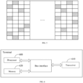
- FIG. 2 is a schematic diagram of a single-symbol DMRS and a double-symbol DMRS according to the related art.
- the horizontal bar grid represents DMRS resource elements (RE) for port 0/1 in the same CDM group
- the dotted grid represents DMRS REs for ports 2/3 in the same CDM group.
- the horizontal bar grid represents DMRS REs for ports 0/1/4/5 in the same CDM group
- the dotted grid represents DMRS REs for ports 2/3/6/7 in the same CDM group.
- DMRS needs to be evenly distributed within the frequency domain resource range for PUSCH multiplexing.
- various embodiments of the present application provide a solution for data transmission between a terminal and a network device. By performing segmenting and bit padding on the encoded bits, interleaving the bit segments obtained by segmenting and performing bit padding in unit of segment, and then performing modulating and transmitting operations, the transmission signals between the terminals are separated as much as possible, and the network device may accurately detect the data from each terminal.
- FIG. 3 is a first schematic flowchart of a method for data transmission according to an embodiment of the present application. The method is performed by a terminal. As shown in FIG. 3 , the method includes the following steps:
- the encoded bits may be bits obtained by encoding in the URAT scheme.
- Padded bit segment refers to a segment of an uncertain bit padded after the encoded bits and each padded bit segment includes one or more uncertain bits.
- each encoded bit segment and each padded bit segment may include an equal quantity of bits.
- each segment includes B bits.
- the above-mentioned uncertain bits may be bits that do not represent specific information (such as 0 or 1), or may be bits that are only used as placeholders.
- the terminal may perform segmenting and bit padding on the encoded bits in different orders.
- the encoded bits may be segmented to obtain M encoded bit segments, and then a segment of multiple uncertain bits may be padded after the last encoded bit segment; or multiple uncertain bits may be padded after the last encoded bit, and then the encoded bits and the padded uncertain bits may be segmented. That is, performing segmenting and bit padding is not specifically limited as long as K bit segments including M encoded bit segments and K-M padded bit segments may be obtained.
- the quantity K of bit segments may be transmitted to the terminal after it is determined by the network device based on the requirements of the dispersion degree of the transmitted signals of each terminal. It may also be determined by the terminal based on the actual needs of the transmitted signal, and there is no specific limitation. K is greater than M. In an embodiment, K may be 5 times or more than 5 times of M.
- the terminal may interleave the K bit segments in unit of segment using an interleaver.
- Each encoded bit segment and each padded bit segment are interleaved with each other, and each encoded bit segment may be dispersed.
- Data symbols obtained by subsequently modulating the encoded bit segments are correspondingly mapped to different REs in a relatively dispersed manner, and the transmission signals between multiple terminals may be separated as much as possible, which is conducive for the network equipment (such as base stations) to detect the data from each terminal.
- the specific interleaving mode is not limited here, and traditional interleaving may be used. For example, interleaving may be completed using a group interleaver in a line-in-column-out manner starting from a specific start position.
- each encoded bit segment may be modulated into at least one to-be-transmitted data symbol.
- QPSK quadrature phase shift keying
- the terminal may modulate the padded bit segments into empty symbols, and no signal is transmitted at the RE corresponding to these empty symbols.
- the padded bit segments may be modulated into empty symbols using traditional modulation, which is not limited here.
- the terminal After modulating, the terminal transmits a signal to the network device by mapping the modulated data symbols to the RE, and no any signal is transmitted at the RE corresponding to the segment formed by the padded bits for placeholders, that is, an empty symbol is transmitted.
- a huge quantity of terminals may use the same procedure to transmit data simultaneously at the configured RE.
- the encoded bit segments may be dispersed and the data symbols obtained by subsequently modulating the encoded bit segments are correspondingly mapped to different REs in a relatively dispersed manner, the transmission signals between the terminals may be separated as much as possible, and the base station may accurately detect the data from each terminal.
- the method further includes: transmitting a demodulation reference signal (DMRS) symbol to the network device based on a resource element (RE) for transmitting the data symbols.
- DMRS demodulation reference signal
- the REs for transmitting the data symbols for the terminal are dispersed in a larger frequency domain resource range.
- the DMRS needs to be evenly distributed in the frequency domain resource range for the PUSCH multiplexing, which will result in a larger DMRS overhead.
- the terminal may also determine the RE for transmitting the DMRS symbol to the network device based on the RE for transmitting the data symbols after segmenting and modulating the encoded bits into data symbols.
- the RE for transmitting the DMRS symbol to the network device is determined based on the RE for transmitting the data symbols, instead of evenly distributing the DMRS in the frequency domain resource range for the PUSCH multiplexing, which may effectively reduce the DMRS overhead.
- transmitting the DMRS symbol to the network device based on the RE for transmitting the data symbols may include transmitting the DMRS symbol to the network device at the RE for transmitting data symbols.
- the DMRS symbol may be mapped to the RE for transmitting data symbols.
- the DMRS symbol may be transmitted at each RE for transmitting data symbols, or may be transmitted at some REs for transmitting data symbols, and the specific situation is not limited.
- transmitting the DMRS symbol to the network device based on the RE for transmitting the data symbols may also include transmitting the DMRS symbol at an RE adjacent to the RE for transmitting data symbols, or transmitting the DMRS symbol at other REs determined based on the RE for transmitting data symbols, and the specific situation is not limited.
- transmitting the DMRS symbol to the network device at the RE for transmitting the data symbols includes:
- the terminal may select one or more to-be-transmitted target DMRS symbols from a DMRS pilot sequence in a specific manner after determining the target data symbol obtained by modulating the target encoded bit segment.
- one or more target DMRS symbols at corresponding positions may be selected from a DMRS pilot sequence based on a position order of the target encoded bit segment in the M interleaved encoded bit segments.
- one or more target DMRS symbols at corresponding positions may be selected from a DMRS pilot sequence based on a position order of RE at which a data symbol exist, that is, from low frequency to high frequency.
- the terminal may multiplex the target data symbol and the target DMRS symbol at the same RE segment by a code division multiplexing mode and transmit them to the network device, where the same RE segment refers to an RE segment including all REs for transmitting the target data symbol.
- the method before performing segmenting and bit padding on the encoded bits to obtain the K bit segments, the method further includes:
- the terminal may receive the indication information transmitted from the network device and process the coded bits based on an associated parameter carried in the indication information.
- K is a total quantity of padded bit segments.
- B is the quantity of bits in a bit segment.
- the quantity B of bits in an encoded bit segment is 2.
- the quantity B of bits in each padded bit segment may also be 2.
- Q is the quantity of DMRS symbols corresponding to the data symbol obtained after an encoded bit segment is modulated.
- Q may take a value greater than or equal to the quantity of antenna ports.
- L is the quantity of REs corresponding to each encoded bit segment, that is, a data symbol obtained by segmenting and modulating an encoded bit segment is transmitted at L REs.
- L may be the quantity of REs to which the data symbol and the DMRS symbol are mapped by code-division multiplexing in case that the data symbol and the DMRS symbol are code-division multiplexed at the same RE segment for transmission.
- the values of parameters such as M, K, B, P, Q, and L in each embodiment of the present application are all positive integers, and specific values can be predetermined based on actual data transmission requirements, which are not limited in the present application.
- FIG. 4 is a second schematic flowchart of a method for data transmission according to an embodiment of the present application.
- the method is performed by a network device (for example, a base station).
- a network device for example, a base station.
- the method includes the following steps:
- the network device may detect and decode metadata bits, and then obtain the specific interleaving mode used by the terminal based on the metadata bits, that is, the specific interleaving mode used by the terminal to interleave K bit segments in units of segments. Therefore, after receiving the data signal transmitted from the terminal, the network device may detect that the terminal has transmitted data symbols at which REs on based on the specific interleaving mode used by the terminal.
- the network device may perform operations such as decoding, deinterleaving and demodulation on the data symbols using the received signal at the RE for transmitting the data symbols based on the channel estimation result to obtain the encoded bits transmitted from the terminal.
- the terminal may disperse the encoded bit segments and may correspondingly map the data symbols obtained by subsequently modulating the encoded bit segments to different REs in a relatively dispersed manner, the transmission signals between the terminals may be separated as much as possible, and the base station may correspondingly accurately detect the data transmitted from each terminal based on the bit segment interleaving used by the terminal.
- completing the detection for the data symbols transmitted from the terminal based on the RE used by the terminal transmitting the data symbols may include:
- the network device may determine the RE for transmitting DMRS symbols based on the RE for transmitting data symbols, where the RE for transmitting DMRS symbols may be an RE for transmitting data symbols, or an RE adjacent to an RE for transmitting data symbols, or other REs determined based on the RE for transmitting data symbols, etc., and the specific situation is not limited, as long as it is consistent with the mode used by the terminal.
- completing the detection for the data symbols transmitted from the terminal based on the RE used by the terminal transmitting the data symbols includes:
- the network device may decode the DMRS symbol segment by segment based on the received signal at the RE to obtain the DMRS symbol transmitted from the terminal, perform channel estimation based on the obtained DMRS, and then perform operations such as decoding, deinterleaving and demodulation of the data symbol based on the channel estimation result and using the received signal at the RE for transmitting the data symbols to obtain the encoded bit transmitted from the terminal.
- the method before receiving the data signal transmitted from the terminal, the method further includes:
- the network device may transmit indication information to the terminal, the terminal may process the encoded bits based on the associated parameters carried in the indication information. In an embodiment, after receiving the transmission signal from the terminal, the network device may also detect the data transmitted from the terminal based on these associated parameters.
- K is a total quantity of padded bit segments.
- B is the quantity of bits in a bit segment.
- the quantity B of bits in an encoded bit segment is 2.
- the quantity B of bits in each padded bit segment may also be 2.
- Q is the quantity of DMRS symbols corresponding to the data symbol obtained after an encoded bit segment is modulated.
- Q may take a value greater than or equal to the quantity of antenna ports.
- L is the quantity of REs corresponding to each encoded bit segment, that is, a data symbol obtained by segmenting and modulating an encoded bit segment is transmitted at L REs.
- L may be the quantity of REs to which the data symbol and the DMRS symbol are mapped by code-division multiplexing in case that the data symbol and the DMRS symbol are code-division multiplexed at the same RE segment for transmission.
- the interleaver is an interleaver with a depth of 200 and 10 rows by 20 columns.
- FIG. 5 is a schematic diagram of interleaved bit segments according to an embodiment of the present application. As shown in FIG. 5 , the blocks filled with oblique lines are segments of encoded bits, and the blocks without pattern filling are segments of uncertain bits.
- Q 1 DMRS symbol at the corresponding position, for example 0.1255-0.6588j, is selected from the pilot sequence, and 1 modulation symbol and 1 DMRS symbol are multiplexed using OCC.
- Embodiment 4 Embodiment at a network device side.
- the methods and the devices are based on the same concept, the implementation of the devices and the methods can be referred to each other since the principles of the methods and the devices are similar, and the same part is not be repeated here.
- FIG. 6 is a schematic structural diagram of a terminal according to an embodiment of the present application.
- the terminal includes a memory 620, a transceiver 610, and a processor 600, where the processor 600 and the memory 620 may also be arranged physically separately.
- the memory 620 is used for storing computer programs; the transceiver 610 is used for receiving and transmitting data under control of the processor 600.
- the transceiver 610 is used for receiving and transmitting data under the control of the processor 600.
- a bus architecture may include any quantity of interconnected buses and bridges, which are linked together through various circuits of one or more processors represented by the processor 600 and one or more memories represented by the memory 620.
- the bus architecture may also link together various other circuits, such as peripherals, voltage regulators, and power management circuits, which are well known in the art, and therefore will not be further described in the present application.
- the bus interface provides an interface.
- the transceiver 610 may be multiple elements, i.e., including a transmitter and a receiver, units for providing communication with various other devices over transmission media including wireless channels, wired channels, fiber optic cables, and the like.
- the processor 600 is responsible for managing the bus architecture and general processing, and the memory 620 may store data used by the processor 600 when performing operations.
- the processor 600 may be a central processing unit (CPU), an application specific integrated circuit (ASIC), a field-programmable gate array (FPGA), or a complex programmable logic device (CPLD), the processor can also use a multi-core architecture.
- CPU central processing unit
- ASIC application specific integrated circuit
- FPGA field-programmable gate array
- CPLD complex programmable logic device
- the processor 600 is configured to perform any one of the methods according to the embodiments of the present application when executing the executable instructions by calling the computer program stored in the memory 620.
- the method includes:
- the method further includes: transmitting a demodulation reference signal (DMRS) symbol to the network device based on a resource element (RE) for transmitting the data symbols.
- DMRS demodulation reference signal
- transmitting the DMRS symbol to the network device based on the RE for transmitting the data symbols includes: transmitting the DMRS symbol to the network device at the RE for transmitting the data symbols.
- transmitting the DMRS symbol to the network device at the RE for transmitting the data symbols includes:
- the method before performing segmenting and bit padding on the encoded bits to obtain the K bit segments, the method further includes:
- FIG. 7 is a schematic structural diagram of a network device according to an embodiment of the present application.
- the network device includes a memory 720, a transceiver 710, and a processor 700, where the processor 700 and the memory 720 may also be arranged physically separately.
- the memory 720 is used for storing computer programs; the transceiver 710 is used for receiving and transmitting data under control of the processor 700.
- the transceiver 710 is used for receiving and transmitting data under the control of the processor 700.
- a bus architecture may include any quantity of interconnected buses and bridges, which are linked together through various circuits of one or more processors represented by the processor 700 and one or more memories represented by the memory 720.
- the bus architecture may also link together various other circuits, such as peripherals, voltage regulators, and power management circuits, which are well known in the art, and therefore will not be further described in the present application.
- the bus interface provides an interface.
- the transceiver 710 may be multiple elements, i.e., including a transmitter and a receiver, units for providing communication with various other devices over transmission media including wireless channels, wired channels, fiber optic cables, and the like.
- the processor 700 is responsible for managing the bus architecture and general processing, and the memory 720 may store data used by the processor 700 when performing operations.
- the processor 700 may be a CPU, ASIC, FPGA or CPLD, and the processor may also use a multi-core architecture.
- the processor 700 is configured to perform any one of the methods according to the embodiments of the present application when executing the executable instructions by calling the computer program stored in the memory 720.
- the method includes:
- completing the detection for the data symbols transmitted from the terminal based on the RE used by the terminal transmitting the data symbols includes:
- the method before receiving the data signal transmitted from the terminal, the method further includes:
- the above-mentioned terminal and the network device according to the embodiments of the present application may implement all the method steps implemented by the above-mentioned method embodiments, and can achieve the same effect.
- the same parts and beneficial effects as the same method embodiments are not repeated here.
- FIG. 8 is a first schematic structural diagram of an apparatus for data transmission according to an embodiment of the present application. As shown in FIG. 8 , the apparatus includes:
- the first transmitting unit 820 is further used for: transmitting a demodulation reference signal (DMRS) symbol to the network device based on a resource element (RE) for transmitting the data symbols.
- DMRS demodulation reference signal
- RE resource element
- transmitting the DMRS symbol to the network device based on the RE for transmitting the data symbols includes: transmitting the DMRS symbol to the network device at the RE for transmitting the data symbols.
- transmitting the DMRS symbol to the network device at the RE for transmitting the data symbols includes:
- the apparatus further includes:
- FIG. 9 is a second schematic structural diagram of an apparatus for data transmission according to an embodiment of the present application. As shown in FIG. 9 , the apparatus includes:
- completing the detection for the data symbols transmitted from the terminal based on the RE used by the terminal transmitting the data symbols includes:
- the apparatus further includes:
- the division of units in the embodiments of the present application is schematic, and is only a logical function division, and there may be other division manners in actual implementation.
- the functional units in the various embodiments of the present application may be integrated into one processing unit, or each unit may exist alone physically, or two or more units may be integrated into one unit.
- the above-mentioned integrated unit may be implemented in the form of hardware or software functional unit.
- the integrated unit is implemented in the form of a software functional unit and sold or used as an independent product, it may be stored in a processor readable storage medium.
- the technical solutions of the present application in essence or a part of the technical solutions that contributes to the prior art, or all or part of the technical solutions, may be embodied in the form of a software product, which is stored in a storage medium, including several instructions to cause a computer device (which may be a personal computer, server, or network side device, etc.) or a processor to perform all or part of the steps of the methods described in the respective embodiments of the present application.
- the storage medium described above includes various media that may store program codes such as U disk, mobile hard disk, read-only memory (ROM), random access memory (RAM), magnetic disk, or a compact disk.
- An embodiment of the present application further provides a computer-readable storage medium storing a computer program that causes a computer to perform the method for data transmission described above.
- the computer-readable storage medium may be any available medium or data storage device that can be accessed by the computer, including but not limited to, a magnetic storage (e.g., a floppy disk, a hard disk, a magnetic tape, a magneto-optical disk (MO), etc.), optical memory (such as CD, DVD, BD, HVD, etc.), and a semiconductor memory (such as ROM, EPROM, EEPROM, non-volatile memory (NAND FLASH), solid-state drive (SSD)), etc.
- a magnetic storage e.g., a floppy disk, a hard disk, a magnetic tape, a magneto-optical disk (MO), etc.
- optical memory such as CD, DVD, BD, HVD, etc.
- semiconductor memory such as ROM, EPROM, EEPROM, non-volatile memory (NAND FLASH), solid-state drive (SSD)
- applicable systems may be a global system of mobile communication (GSM) system, a code division multiple access (CDMA) system, a wideband code division multiple access (WCDMA) general packet wireless service (general packet radio service, GPRS) system, a long term evolution (LTE) system, a LTE frequency division duplex (FDD) system, a LTE time division duplex (TDD) system, a long term evolution advanced (LTE-A) system, a universal mobile telecommunication system (UMTS), a worldwide interoperability for microwave access (WiMAX) system, a 5G New Radio (NR) system, etc.
- GSM global system of mobile communication
- CDMA code division multiple access
- WCDMA wideband code division multiple access
- GPRS general packet wireless service
- LTE long term evolution
- FDD frequency division duplex
- TDD LTE time division duplex
- LTE-A long term evolution advanced
- UMTS universal mobile telecommunication system
- WiMAX worldwide interoperability for microwave access
- NR
- the terminal in the embodiments of the present application may be a device that provides voice and/or data connectivity to a user, a handheld device with a wireless connection function, or other processing device connected to a wireless modem.
- the names of the terminal may be different.
- the terminal may be called as user equipment (UE).
- a wireless terminal may communicate with one or more core networks (CN) via a radio access network (RAN), and the wireless terminal may be a mobile terminal, such as a mobile phone (or "cellular" phone) and computers with mobile terminal, e.g., a portable mobile device, a pocket-sized mobile device, a hand-held mobile device, a computer-built mobile device or a vehicle-mounted mobile device, which exchange language and/or data with the radio access network.
- a personal communication service (PCS) phone a radio phone, a session initiated protocol (SIP) phone, a wireless local loop (WLL) station, a personal digital assistant (PDA) and other devices.
- PCS personal communication service
- SIP session initiated protocol
- WLL wireless local loop
- PDA personal digital assistant
- a wireless terminal device may also be called a system, a subscriber unit, a subscriber station, a mobile station, a mobile, a remote station, an access point, a remote terminal, an access terminal, a user terminal, a user agent, and a user device, which are not limited in the embodiments of the present application.
- the network side device involved in the embodiments of the present application may be a base station, and the base station may include a plurality of cells providing services for the terminal.
- the network side device may also be called an access point, or may be a device in the access network that communicates with wireless terminal through one or more sectors on the air interface, or other names.
- Network side device may be used to exchange received air frames with Internet Protocol (IP) packets, and act as a router between wireless terminal and the rest of the access network, and the rest of the access network may include an Internet protocol (IP) communication network.
- IP Internet Protocol
- the network side devices may also coordinate attribute management for the air interface.
- the network side device in the embodiments of the present application may be a base transceiver station (BTS) in a global system for mobile communications (GSM) or a code division multiple access (CDMA), may also be a node B in a wide-band code division multiple access (WCDMA), may also be an evolutional node B (eNB or e-Node B) in a long term evolution (LTE) system, a 5G base station (gNB) in 5G network architecture (next generation system), may also be a home evolved node B (HeNB), a relay node (relay node), a femto, a pico base station (pico), etc., which are not limited in the embodiments of the present application.
- a network side device may include a centralized unit (CU) node and a distributed unit (DU) node, and the centralized unit and the distributed unit may also be geographically separated.
- Multi-input multi-output (MIMO) transmission may be performed between the network side device and the UE using one or more antennas and the MIMO transmission may be single user MIMO (SU-MIMO) or multiple user MIMO (MU-MIMO).
- MIMO transmission may be 2D-MIMO, 3D-MIMO, FD-MIMO, or massive-MIMO, and may also be diversity transmission, precoding transmission, or beamforming transmission.
- embodiments of the present application may be provided as a method, system, or computer program product. Accordingly, the present application may take the form of an entirely hardware embodiment, an entirely software embodiment, or an embodiment combining software and hardware aspects. Furthermore, the present application may take the form of a computer program product embodied on one or more computer-usable storage media having computer-usable program code embodied therein, including but not limited to disk storage, optical storage, and the like.
- processor-executable instructions may also be stored in a processor-readable memory capable of directing a computer or other programmable data processing apparatus to operate in a particular manner, and the instructions stored in the processor-readable memory may result in a manufacture including instruction means, the instruction means can perform the functions specified in one or more flows of the flowchart and/or one or more blocks of the block diagram.
- processor-executable instructions may also be loaded onto a computer or other programmable data processing device to cause a series of operational steps to be performed on the computer or other programmable device to produce a computer-implemented process and instructions performed on the computer or other programmable devices provide steps for performing the functions specified in one or more flows of the flowchart and/or one or more blocks of the block diagram.
Landscapes
- Engineering & Computer Science (AREA)
- Signal Processing (AREA)
- Computer Networks & Wireless Communication (AREA)
- Quality & Reliability (AREA)
- Detection And Prevention Of Errors In Transmission (AREA)
- Mobile Radio Communication Systems (AREA)
Applications Claiming Priority (2)
| Application Number | Priority Date | Filing Date | Title |
|---|---|---|---|
| CN202210714204.6A CN117318879A (zh) | 2022-06-22 | 2022-06-22 | 数据传输方法、设备、装置及存储介质 |
| PCT/CN2023/099385 WO2023246525A1 (zh) | 2022-06-22 | 2023-06-09 | 数据传输方法、设备、装置及存储介质 |
Publications (1)
| Publication Number | Publication Date |
|---|---|
| EP4546677A1 true EP4546677A1 (de) | 2025-04-30 |
Family
ID=89248644
Family Applications (1)
| Application Number | Title | Priority Date | Filing Date |
|---|---|---|---|
| EP23826174.7A Pending EP4546677A1 (de) | 2022-06-22 | 2023-06-09 | Datenübertragungsverfahren, -vorrichtung und -vorrichtung sowie speichermedium |
Country Status (6)
| Country | Link |
|---|---|
| US (1) | US20250358049A1 (de) |
| EP (1) | EP4546677A1 (de) |
| JP (1) | JP7830710B2 (de) |
| KR (1) | KR20250016347A (de) |
| CN (1) | CN117318879A (de) |
| WO (1) | WO2023246525A1 (de) |
Families Citing this family (1)
| Publication number | Priority date | Publication date | Assignee | Title |
|---|---|---|---|---|
| CN117118579A (zh) * | 2022-05-16 | 2023-11-24 | 大唐移动通信设备有限公司 | 元数据传输方法、装置及存储介质 |
Family Cites Families (10)
| Publication number | Priority date | Publication date | Assignee | Title |
|---|---|---|---|---|
| CN103354537B (zh) * | 2007-06-14 | 2017-03-29 | 北京三星通信技术研究有限公司 | 传输块分段传输的设备和方法 |
| US7890834B2 (en) * | 2007-06-20 | 2011-02-15 | Motorola Mobility, Inc. | Apparatus comprising a circular buffer and method for assigning redundancy versions to a circular buffer |
| CN102136886A (zh) * | 2011-04-14 | 2011-07-27 | 西安新邮通信设备有限公司 | 一种正交重复累积码的编译码方法及装置 |
| US9160485B2 (en) * | 2012-12-03 | 2015-10-13 | Lg Electronics Inc. | Method and apparatus for encoding transport block |
| US10313057B2 (en) * | 2016-06-01 | 2019-06-04 | Qualcomm Incorporated | Error detection in wireless communications using sectional redundancy check information |
| CN108631941B (zh) * | 2017-03-24 | 2021-02-23 | 华为技术有限公司 | 通信方法和装置 |
| CN109525359B (zh) * | 2017-09-18 | 2022-03-11 | 华为技术有限公司 | 数据传输的方法和设备 |
| WO2020166229A1 (ja) * | 2019-02-13 | 2020-08-20 | ソニー株式会社 | 通信装置及び通信方法 |
| US12302391B2 (en) * | 2020-09-03 | 2025-05-13 | Intel Corporation | Intelligent transport system co-channel coexistence frame structure with asymmetric gap durations |
| CN113612579A (zh) * | 2021-07-23 | 2021-11-05 | 广州慧睿思通科技股份有限公司 | 基于qc_ldpc码的数据处理方法、通信装置、设备和存储介质 |
-
2022
- 2022-06-22 CN CN202210714204.6A patent/CN117318879A/zh active Pending
-
2023
- 2023-06-09 JP JP2024575305A patent/JP7830710B2/ja active Active
- 2023-06-09 EP EP23826174.7A patent/EP4546677A1/de active Pending
- 2023-06-09 US US18/871,489 patent/US20250358049A1/en active Pending
- 2023-06-09 WO PCT/CN2023/099385 patent/WO2023246525A1/zh not_active Ceased
- 2023-06-09 KR KR1020247043561A patent/KR20250016347A/ko active Pending
Also Published As
| Publication number | Publication date |
|---|---|
| WO2023246525A1 (zh) | 2023-12-28 |
| KR20250016347A (ko) | 2025-02-03 |
| CN117318879A (zh) | 2023-12-29 |
| JP7830710B2 (ja) | 2026-03-16 |
| JP2025520665A (ja) | 2025-07-03 |
| US20250358049A1 (en) | 2025-11-20 |
Similar Documents
| Publication | Publication Date | Title |
|---|---|---|
| US12376125B2 (en) | Communication method and communication apparatus | |
| US11239970B2 (en) | Reference signal sending method, reference signal receiving method, and communications apparatus | |
| US11128510B2 (en) | Data transmission method, user equipment, and network side device | |
| US11212054B2 (en) | Data transmission method and apparatus | |
| AU2016400171B2 (en) | Information processing method, terminal device, network device, and communication system | |
| EP4084387A1 (de) | Datenübertragungsverfahren und -vorrichtung | |
| US20160028518A1 (en) | A wireless device, a network node and methods therein for transmitting control information in a d2d communication | |
| EP3226453B1 (de) | Verfahren und vorrichtung zur übertragung von indikationsinformationen | |
| CN109155708A (zh) | Pusch中的harq-ack复用 | |
| US20220006683A1 (en) | Data transmission method and communication apparatus | |
| CN107079466A (zh) | 传输指示信息的方法和装置 | |
| CN108631815A (zh) | 数据传输方法、网络设备及终端设备 | |
| EP4546677A1 (de) | Datenübertragungsverfahren, -vorrichtung und -vorrichtung sowie speichermedium | |
| US20180343093A1 (en) | Signal transmission method and apparatus | |
| US11184885B2 (en) | Information transmission method, terminal device, and network device | |
| EP3579434A1 (de) | Datenübertragungsverfahren, netzwerkvorrichtung und endgerätevorrichtung | |
| CN119276439A (zh) | 信息传输方法、装置、终端及网络设备 |
Legal Events
| Date | Code | Title | Description |
|---|---|---|---|
| STAA | Information on the status of an ep patent application or granted ep patent |
Free format text: STATUS: THE INTERNATIONAL PUBLICATION HAS BEEN MADE |
|
| PUAI | Public reference made under article 153(3) epc to a published international application that has entered the european phase |
Free format text: ORIGINAL CODE: 0009012 |
|
| STAA | Information on the status of an ep patent application or granted ep patent |
Free format text: STATUS: REQUEST FOR EXAMINATION WAS MADE |
|
| 17P | Request for examination filed |
Effective date: 20241212 |
|
| AK | Designated contracting states |
Kind code of ref document: A1 Designated state(s): AL AT BE BG CH CY CZ DE DK EE ES FI FR GB GR HR HU IE IS IT LI LT LU LV MC ME MK MT NL NO PL PT RO RS SE SI SK SM TR |
|
| DAV | Request for validation of the european patent (deleted) | ||
| DAX | Request for extension of the european patent (deleted) |