EP4546730A1 - Procédé et appareil de traitement de données, et dispositif - Google Patents
Procédé et appareil de traitement de données, et dispositif Download PDFInfo
- Publication number
- EP4546730A1 EP4546730A1 EP22954267.5A EP22954267A EP4546730A1 EP 4546730 A1 EP4546730 A1 EP 4546730A1 EP 22954267 A EP22954267 A EP 22954267A EP 4546730 A1 EP4546730 A1 EP 4546730A1
- Authority
- EP
- European Patent Office
- Prior art keywords
- block
- sub
- encoded
- data corresponding
- code
- Prior art date
- Legal status (The legal status is an assumption and is not a legal conclusion. Google has not performed a legal analysis and makes no representation as to the accuracy of the status listed.)
- Pending
Links
Images


Classifications
-
- H—ELECTRICITY
- H04—ELECTRIC COMMUNICATION TECHNIQUE
- H04L—TRANSMISSION OF DIGITAL INFORMATION, e.g. TELEGRAPHIC COMMUNICATION
- H04L1/00—Arrangements for detecting or preventing errors in the information received
- H04L1/004—Arrangements for detecting or preventing errors in the information received by using forward error control
- H04L1/0056—Systems characterized by the type of code used
- H04L1/0057—Block codes
-
- H—ELECTRICITY
- H03—ELECTRONIC CIRCUITRY
- H03M—CODING; DECODING; CODE CONVERSION IN GENERAL
- H03M13/00—Coding, decoding or code conversion, for error detection or error correction; Coding theory basic assumptions; Coding bounds; Error probability evaluation methods; Channel models; Simulation or testing of codes
- H03M13/03—Error detection or forward error correction by redundancy in data representation, i.e. code words containing more digits than the source words
- H03M13/05—Error detection or forward error correction by redundancy in data representation, i.e. code words containing more digits than the source words using block codes, i.e. a predetermined number of check bits joined to a predetermined number of information bits
- H03M13/13—Linear codes
-
- H—ELECTRICITY
- H03—ELECTRONIC CIRCUITRY
- H03M—CODING; DECODING; CODE CONVERSION IN GENERAL
- H03M13/00—Coding, decoding or code conversion, for error detection or error correction; Coding theory basic assumptions; Coding bounds; Error probability evaluation methods; Channel models; Simulation or testing of codes
- H03M13/29—Coding, decoding or code conversion, for error detection or error correction; Coding theory basic assumptions; Coding bounds; Error probability evaluation methods; Channel models; Simulation or testing of codes combining two or more codes or code structures, e.g. product codes, generalised product codes, concatenated codes, inner and outer codes
- H03M13/2906—Coding, decoding or code conversion, for error detection or error correction; Coding theory basic assumptions; Coding bounds; Error probability evaluation methods; Channel models; Simulation or testing of codes combining two or more codes or code structures, e.g. product codes, generalised product codes, concatenated codes, inner and outer codes using block codes
-
- H—ELECTRICITY
- H03—ELECTRONIC CIRCUITRY
- H03M—CODING; DECODING; CODE CONVERSION IN GENERAL
- H03M13/00—Coding, decoding or code conversion, for error detection or error correction; Coding theory basic assumptions; Coding bounds; Error probability evaluation methods; Channel models; Simulation or testing of codes
- H03M13/61—Aspects and characteristics of methods and arrangements for error correction or error detection, not provided for otherwise
- H03M13/611—Specific encoding aspects, e.g. encoding by means of decoding
-
- H—ELECTRICITY
- H03—ELECTRONIC CIRCUITRY
- H03M—CODING; DECODING; CODE CONVERSION IN GENERAL
- H03M13/00—Coding, decoding or code conversion, for error detection or error correction; Coding theory basic assumptions; Coding bounds; Error probability evaluation methods; Channel models; Simulation or testing of codes
- H03M13/61—Aspects and characteristics of methods and arrangements for error correction or error detection, not provided for otherwise
- H03M13/615—Use of computational or mathematical techniques
- H03M13/616—Matrix operations, especially for generator matrices or check matrices, e.g. column or row permutations
-
- H—ELECTRICITY
- H04—ELECTRIC COMMUNICATION TECHNIQUE
- H04L—TRANSMISSION OF DIGITAL INFORMATION, e.g. TELEGRAPHIC COMMUNICATION
- H04L1/00—Arrangements for detecting or preventing errors in the information received
- H04L1/004—Arrangements for detecting or preventing errors in the information received by using forward error control
- H04L1/0041—Arrangements at the transmitter end
-
- H—ELECTRICITY
- H03—ELECTRONIC CIRCUITRY
- H03M—CODING; DECODING; CODE CONVERSION IN GENERAL
- H03M13/00—Coding, decoding or code conversion, for error detection or error correction; Coding theory basic assumptions; Coding bounds; Error probability evaluation methods; Channel models; Simulation or testing of codes
- H03M13/63—Joint error correction and other techniques
- H03M13/635—Error control coding in combination with rate matching
- H03M13/6362—Error control coding in combination with rate matching by puncturing
-
- H—ELECTRICITY
- H04—ELECTRIC COMMUNICATION TECHNIQUE
- H04L—TRANSMISSION OF DIGITAL INFORMATION, e.g. TELEGRAPHIC COMMUNICATION
- H04L1/00—Arrangements for detecting or preventing errors in the information received
- H04L1/004—Arrangements for detecting or preventing errors in the information received by using forward error control
- H04L1/0056—Systems characterized by the type of code used
- H04L1/0067—Rate matching
Definitions
- This application relates to the field of communication technologies, and in particular, to a data processing method, an apparatus, and a device.
- a polar code is a channel encoding scheme that can be strictly proved to "reach" a Shannon channel capacity, features good performance, low complexity, and the like, and may be applied to a 5th generation (5 th generation, 5G) communication system and a future communication system.
- a mother code length of the polar code is an integer power of 2 (that is, 2 n ).
- a code length N required for actual communication is not the mother code length (for example, is not 2 n )
- a code length matching process needs to be further implemented in a manner of puncturing, retransmission, and the like, to implement rate matching.
- an existing protocol standard specifies a sequence construction manner and a rate matching mode that is based on sub-block interleaving.
- sequence construction manner is applicable only to an encoding matrix with the mother code length of 2 n .
- construction is performed only through Gaussian approximation and a quick and flexible construction method and a corresponding rate matching mode are absent.
- This application provides a data processing method, an apparatus, and a device. According to the method, information bit construction and rate matching can be quickly performed on encoded data without a mother code length of an integer multiple of 2 n .
- This construction method is simple and effective, and helps improve system performance.
- this application provides a data processing method.
- the data processing method may be performed by a terminal device or a network device.
- An example in which the terminal device is an execution body and the terminal device is an encoding side is used.
- the terminal device obtains K information bits, determines a length of a to-be-encoded block based on K , and determines a quantity of information bits in each to-be-encoded sub-block in the to-be-encoded block based on the length of the to-be-encoded block and an allocation sequence.
- the allocation sequence is used to describe quantities of information bits in all to-be-encoded sub-blocks except a last to-be-encoded sub-block in the to-be-encoded block in a case of a same code rate and a same to-be-encoded sub-block size.
- the terminal device encodes the to-be-encoded block to obtain encoded data, and sends the encoded data.
- an information bit construction and encoding method based on the allocation sequence is designed.
- the information bit construction method is simple and effective, and helps improve system performance and reduce system power consumption.
- the length of the to-be-encoded block and a quantity of to-be-encoded sub-blocks in the to-be-encoded block are designed, so that a quantity of code sub-blocks is determined, and the size of the code sub-block is designed to be 2 n .
- the code rate and the size of the code sub-block are fixed, to facilitate information bit construction that is based on the allocation sequence.
- the allocation sequence is further designed to support simpler information bit construction.
- information bit construction and rate matching when a length of the code sub-block is less than an integer multiple of 2 n can be supported in the method.
- that the terminal device determines a quantity of information bits in each to-be-encoded sub-block in the to-be-encoded block based on the length of the to-be-encoded block and an allocation sequence may specifically include:
- the length of the to-be-encoded sub-block and the quantity of information bits in each to-be-encoded sub-block in the to-be-encoded block are designed, so that information bit construction for an encoding matrix G' can be supported.
- that the terminal device determines a quantity of information bits in each to-be-encoded sub-block in the to-be-encoded block based on the length of the to-be-encoded block and an allocation sequence may specifically include:
- the length of the to-be-encoded sub-block and the quantity of information bits in each to-be-encoded sub-block in the to-be-encoded block are designed, so that information bit construction for an encoding matrix G can be supported.
- that the terminal device encodes the to-be-encoded block to obtain encoded data may specifically include:
- a new encoding matrix G for a polar code is designed.
- the terminal device encodes the to-be-encoded information bits by using the encoding matrix G
- the terminal device may encode the part of information bits and send encoded data, to implement stream encoding and help reduce sizes of an encoder and a buffer in the terminal device.
- the encoded data (the encoded data is obtained based on the encoding matrix G ) is sent, an ( m -1) th to-be-encoded sub-block is first sent, and then an i th code sub-block is successively sent, where i satisfies 0 ⁇ i ⁇ m -2.
- an order of sending the encoded data is designed, to facilitate stream decoding on a decoding side.
- an i th code sub-block is successively sent, where i satisfies 0 ⁇ i ⁇ m -1.
- the method in the first aspect may alternatively be performed by the network device.
- the network device is an encoding side
- the terminal device is a decoding side.
- this application provides another data processing method.
- the data processing method may be performed by a terminal device or a network device.
- An example in which the network device is an execution body and the network device is a decoding side is used.
- the network device receives encoded data, and decodes the encoded data to obtain decoded data.
- the encoded data is obtained by encoding a to-be-encoded block.
- the to-be-encoded block includes a plurality of to-be-encoded sub-blocks. A quantity of information bits in each to-be-encoded sub-block in the to-be-encoded block is determined based on a length of the to-be-encoded block and an allocation sequence.
- the allocation sequence is used to describe quantities of information bits in all to-be-encoded sub-blocks except a last to-be-encoded sub-block in the to-be-encoded block in a case of a same code rate and a same to-be-encoded sub-block size.
- the encoded data includes a plurality of code blocks, and quantities of information bits in the plurality of code blocks are designed according to a specific rule.
- stream decoding can be implemented for the encoded data.
- that the network device decodes the encoded data to obtain decoded data may specifically include:
- the network device performs decoding based on the 0 th receiving sub-block that is received for the first time and the adjacent 1 st receiving sub-block, to implement stream decoding.
- the 0 th receiving sub-block is enhanced, which facilitates stream decoding based on the enhanced 0 th receiving sub-block in a subsequent decoding process.
- the network device obtains marked data corresponding to a q th receiving sub-block, where the q th receiving sub-block is a ( q -1) th code sub-block, and q is 2 ⁇ q ⁇ m -1; performs an F operation on the marked data corresponding to the q th receiving sub-block and enhanced marked data corresponding to the 0 th receiving sub-block, to obtain marked data corresponding to the q th receiving sub-block after the F operation; performs polar code decoding on the marked data corresponding to the q th receiving sub-block after the F operation, to obtain decoded data corresponding to the q th receiving sub-block; and enhances, based on the marked data corresponding to the q th receiving sub-block and the decoded data corresponding to the q th receiving sub-block, the enhanced marked data corresponding to the 0 th receiving sub-block.
- a 2 nd receiving sub-block to an ( m -1) th receiving sub-block are decoded by using a same method.
- the marked data corresponding to the 0 th receiving sub-block is continuously enhanced, which facilitates stream decoding.
- that the network device decodes the encoded data to obtain decoded data may specifically include:
- the network device obtains marked data corresponding to a p th receiving sub-block, where the p th receiving sub-block is a p th code sub-block, and p is 2 ⁇ p ⁇ m -1; performs an F operation on the marked data corresponding to the p th receiving sub-block and enhanced marked data corresponding to a ( p -1) th receiving sub-block, to obtain marked data corresponding to the ( p -1) th receiving sub-block after the F operation; performs polar code decoding on the marked data corresponding to the ( p -1) th receiving sub-block after the F operation, to obtain decoded data corresponding to the ( p -1) th receiving sub-block; and enhances, based on the enhanced marked data corresponding to the ( p -1) th receiving sub-block and the decoded data corresponding to the ( p -1) th receiving sub-block, the marked data corresponding to the p th receiving sub-block.
- the method in the second aspect may alternatively be performed by the terminal device.
- the network device is an encoding side
- the terminal device is a decoding side.
- an embodiment of this application provides a data processing apparatus.
- the data processing apparatus may be a terminal device, or may be an apparatus in the terminal device, or may be an apparatus that can be used with the terminal device.
- the data processing apparatus may include a one-to-one corresponding module for performing the method/operation/step/action described in the first aspect and the second aspect.
- the module may be a hardware circuit, or may be software, or may be implemented by a combination of a hardware circuit and software.
- the apparatus may include a processing unit and a transceiver unit.
- the data processing apparatus can also achieve effects that can be achieved in the first aspect and the second aspect.
- an embodiment of this application provides a data processing apparatus.
- the data processing apparatus may be a network device, or may be an apparatus in the network device, or may be an apparatus that can be used with the network device.
- the data processing apparatus may include a one-to-one corresponding module for performing the method/operation/step/action described in the first aspect and the second aspect.
- the module may be a hardware circuit, or may be software, or may be implemented by a combination of a hardware circuit and software.
- the data processing apparatus may include a processing unit and a transceiver unit.
- the data processing apparatus can also achieve effects that can be achieved in the first aspect and the second aspect.
- an embodiment of this application provides a communication apparatus.
- the communication apparatus includes an input/output interface and a logic circuit.
- the input/output interface is configured to input or output data.
- the logic circuit processes the data according to the method in any one of the first aspect or the possible implementations of the first aspect, to obtain processed data.
- an embodiment of this application provides a communication apparatus.
- the communication apparatus includes an input/output interface and a logic circuit.
- the input/output interface is configured to input or output data.
- the logic circuit processes the data according to the method in any one of the second aspect or the possible implementations of the second aspect, to obtain processed data.
- an embodiment of this application provides a communication device, including a processor.
- the processor is coupled to a memory.
- the memory is configured to store instructions.
- the terminal device is enabled to implement the method in any one of the possible implementations of the first aspect or the second aspect.
- the communication device is a terminal device.
- the communication device is a network device.
- this application provides a communication system.
- the communication system includes one or more of the data processing apparatuses provided in the third aspect and the fourth aspect.
- the communication system includes the terminal device and the network device provided in the seventh aspect.
- the communication system includes a transmitting end and a receiving end.
- the transmitting end is configured to perform the method in any one of the first aspect or the possible implementations of the first aspect.
- the receiving end is configured to perform the method in any one of the second aspect or the possible implementations of the second aspect.
- this application provides a chip system.
- the chip system includes a processor, and may further include a memory, configured to implement the method in any one of the first aspect or the possible implementations of the first aspect, or the method in any one of the second aspect or the possible implementations of the second aspect.
- the chip system may include a chip, or may include a chip and another discrete component.
- the interface in the chip may be an input/output interface, a pin, a circuit, or the like.
- the chip system may be a system on chip (system on chip, SoC), or may be a baseband chip, or the like.
- the baseband chip may include a processor, a channel encoder, a digital signal processor, a modem, an interface module, and the like.
- this application provides a computer-readable storage medium.
- the computer-readable storage medium stores a computer program.
- the computer program is executed by a processor to implement the method in any one of the first aspect or the possible implementations of the first aspect, or the method in any one of the second aspect or the possible implementations of the second aspect.
- this application provides a computer program product.
- the computer program product includes instructions. When the instructions are run on a computer, the computer is enabled to perform the method in any one of the first aspect or the possible implementations of the first aspect, or the method in any one of the second aspect or the possible implementations of the second aspect.
- “/” may represent an “or” relationship between associated objects.
- A/B may represent A or B.
- “and/or” may indicate that there are three relationships between associated objects.
- a and/or B may represent the following three cases: Only A exists, both A and B exist, and only B exists, where A and B may be singular or plural.
- terms such as “first” and “second” may be used to distinguish between technical features with same or similar functions. The terms such as “first” and “second” do not limit a quantity and an execution sequence, and the terms such as “first” and “second” do not limit a definite difference.
- example or “for example” are used to represent an example, an illustration, or a description. Any embodiment or design scheme described as “example” or “for example” should not be explained as being more preferred or having more advantages than another embodiment or design scheme.
- the terms such as “example” or “for example” are used to present a related concept in a specific manner for ease of understanding.
- This application provides a data processing method. According to the method, an information bit construction and encoding method based on an allocation sequence is designed.
- the data processing method may be applied to a communication system, and a system architecture is shown in FIG. 1 .
- the communication system includes a network device and a terminal device, and the network device may provide a communication service for the terminal device.
- the communication system mentioned in this application includes but is not limited to: a narrowband-internet of things (narrowband-Internet of things, NB-IoT) system, a global system for mobile communications (global system for mobile communications, GSM), an enhanced data rate for GSM evolution (enhanced data rate for GSM evolution, EDGE) system, a wideband code division multiple access (wideband code division multiple access, WCDMA) system, a code division multiple access 2000 (code division multiple access, CDMA2000) system, a time division-synchronization code division multiple access (time division-synchronization code division multiple access, TD-SCDMA) system, a long term evolution (long term evolution, LTE) system, three application scenarios of a 5G mobile communication system: enhanced mobile broadband (enhanced mobility broad band, eMBB), ultra-reliable and low-latency communications (ultra-reliable and low-latency communications, URLLC), and enhanced machine-type communication (enhanced machine-type communication, eMTC), and a future communication system
- the network device may be a device that can communicate with the terminal device.
- the network device may be a base station, a relay station, or an access point.
- the base station may be a base transceiver station (base transceiver station, BTS) in a global system for mobile communications (global system for mobile communications, GSM) or a code division multiple access (code division multiple access, CDMA) network, or may be a 3G base station NodeB in a wideband code division multiple access (wideband code division multiple access, WCDMA) system, or may be an evolved NodeB (eNB or eNodeB for short) in a long term evolution (long term evolution, LTE) system.
- the network device may alternatively be a satellite in a satellite communication system.
- the network device may alternatively be a radio controller in a cloud radio access network (cloud radio access network, CRAN) scenario.
- the network device may alternatively be a network device in a 5G network or a network device (for example, a gNodeB) in a future evolved public land mobile network (public land mobile network, PLMN) network.
- the network device may alternatively be a wearable device, an uncrewed aerial vehicle, a device in the internet of vehicles (for example, a vehicle to everything (vehicle to everything, V2X) device), a communication device in device to device (device to device, D2D) communication, or a network device used in a future communication system.
- the terminal device may be user equipment (user equipment, UE), an access terminal, a terminal unit, a terminal station, a mobile station, a remote station, a remote terminal, a mobile device, a terminal, a wireless communication device, a terminal agent, a terminal apparatus, or the like.
- user equipment user equipment
- UE user equipment
- an access terminal a terminal unit, a terminal station, a mobile station, a remote station, a remote terminal, a mobile device, a terminal, a wireless communication device, a terminal agent, a terminal apparatus, or the like.
- the access terminal may be a cellular phone, a cordless phone, a session initiation protocol (session initiation protocol, SIP) phone, a wireless local loop (wireless local loop, WLL) station, a personal digital assistant (personal digital assistant, PDA), a handheld device with a wireless communication function, a computing device, another processing device connected to a wireless modem, a wearable device, an uncrewed aerial vehicle, a V2X device, a D2D device, a terminal device in the 5G network, a terminal device in the future evolved PLMN network, a terminal device in the future communication system, or the like.
- SIP session initiation protocol
- WLL wireless local loop
- PDA personal digital assistant
- this application includes an encoding scheme, and may be used for a dedicated network device or a general-purpose device, may be used for the network device, or may be used for various terminal devices or the like.
- This application may be implemented by using a dedicated chip (for example, an application-specific integrated circuit (application-specific integrated circuit, ASIC)), or may be implemented by using a programmable chip (for example, a field programmable gate array (field programmable gate array, FPGA)), or may be implemented by using software (program code in a memory). This is not limited in this application.
- a polar code is a channel encoding scheme that can be strictly proved to reach a channel capacity.
- the polar code features high performance, low complexity, a flexible matching manner, and the like.
- the polar code has been determined as an uplink and/or downlink control channel encoding scheme in a 5th generation mobile communication (5 th generation, 5G) control channel enhanced mobile broadband (enhanced mobile broadband, eMBB) scenario.
- 5G 5th generation mobile communication
- eMBB enhanced mobile broadband
- FIG. 2 is a diagram of encoding a polar code of 8 ⁇ 8.
- To-be-encoded bits are sorted based on reliability of the to-be-encoded bits, and are successively arranged at different locations in a to-be-encoded block.
- a bit with high reliability is set as an information bit (data)
- a bit with low reliability is set as a frozen (frozen) bit.
- a value of the frozen bit is usually set to 0, and is known to both a transmitting end and a receiving end during actual transmission. As shown in FIG.
- u 2 , u 7 , u 6 , u 5 , u 3 are four bits with higher reliability and are respectively set as information bits
- u 4 , u 2 , u 1 , u 0 are four bits with lower reliability and are respectively set as frozen bits.
- the polar code is a linear block code.
- u 1 N u 1 , u 2 , ... , u N is a binary row vector, and has a length of N (that is, a code length).
- G N is a matrix of N ⁇ N
- each element in the matrix is a matrix of 2 n ⁇ 2 n
- each element in a diagonal of the matrix is a matrix G N'
- each element in a bottom edge of the matrix is a matrix G N'
- an element other than the elements in the diagonal and the bottom edge is a matrix O .
- a decoding side may decode the encoded data. For example, a decoding process is shown in FIG. 3 .
- the decoding side may calculate the mean value change of the LLR of each G N' based on the encoding matrix G . It is assumed that a mean value of a receiving LLR is L on an additive white Gaussian noise (additive white Gaussian noise, AWGN) channel.
- AWGN additive white Gaussian noise
- GAF Gaussian approximate function
- GAF Gaussian approximate function
- L ⁇ m ⁇ 1 N ′ m ⁇ L L ⁇ i N ′ is an LLR mean value of any code sub-block other than a last code sub-block in m-1 code sub-blocks
- L ⁇ m ⁇ 1 N ′ is an LLR mean value of the last code sub-block.
- capacities of the other m-1 code sub-blocks are related only to sequence numbers i of the m-1 code sub-blocks, and are unrelated to a total quantity m of code sub-blocks in a code block.
- each element in the matrix is a matrix of 2 n ⁇ 2 n
- each element in a lower triangular area of the matrix is the matrix G N'
- an element in the matrix except the lower triangular area is the matrix O .
- a mother code length of the encoding matrix Gis N' m ⁇ 2 n .
- a decoding side may decode the encoded data. For example, a decoding process is shown in FIG. 4 .
- the decoding side may calculate the mean value change of the LLR of each G N' based on the encoding matrix G'. It is assumed that a mean value of a receiving LLR is L on an AWGN channel.
- a GAF may be used to calculate an LLR distribution mean value of each G N' after being decoupled from a last coupling sub-block. Therefore, an LLR mean value of each code sub-block (receiving sub-block) with a size of G N' when ordinary polar code decoding is performed may be calculated.
- L ⁇ m ⁇ 1 N ′ m ⁇ L
- L ⁇ i N ′ is an LLR mean value of any code sub-block other than a last code sub-block in m -1 code sub-blocks
- L ⁇ m ⁇ 1 N ′ is an LLR mean value of the last code sub-block.
- capacities of the other m -1 code sub-blocks are related only to sequence numbers i of the m -1 code sub-blocks, and are unrelated to a total quantity m of code sub-blocks in a code block.
- LLR mean value distribution of each sub-block is shown in the formula (1). Capacities of all mutually corresponding sub-blocks/information bits reflected in respective decoding diagrams of the two encoding matrices are consistent based on a capacity calculation result, so that a same information construction method may be used.
- FIG. 5a For another example, FIG.
- FIG. 5a and FIG. 5b other than a last code sub-block, other code sub-blocks belonging to a same column are allocated with a same quantity of information bits or a difference of only one or two information bits.
- an allocation sequence may be used to describe quantities of information bits in all code sub-blocks except the last code sub-block in the code block in a case of a same code rate and a same code sub-block size. It may be understood that, because a quantity of information bits included in a code sub-block and a quantity of information bits included in a to-be-encoded sub-block are the same, and lengths of the to-be-encoded sub-block and the code sub-block are also the same, the allocation sequence may also be used to describe quantities of information bits in all to-be-encoded sub-blocks except a last to-be-encoded sub-block in the to-be-encoded block in a case of a same code rate and a same to-be-encoded sub-block size.
- the F operation is a basic decoding operation of the polar code, and a predefined F function (f-function) is used for processing.
- the G operation is a basic decoding operation of the polar code, and a predefined G function (g-function) is used for processing.
- FIG. 6 is a schematic flowchart of a first data processing method according to this application.
- the data processing method may be performed by a terminal device, or may be performed by a network device, an encoding procedure is mainly performed, and the following steps are included.
- S102 Determine a length of a to-be-encoded block based on the K information bits.
- S103 Determine a quantity of information bits in each to-be-encoded sub-block in the to-be-encoded block based on the length of the to-be-encoded block and an allocation sequence.
- the to-be-encoded block carries the K information bits.
- m E N ′ .
- the to-be-encoded block corresponds to a code block
- the to-be-encoded sub-block corresponds to a code sub-block.
- the allocation sequence is used to describe quantities of information bits in all to-be-encoded sub-blocks except a last to-be-encoded sub-block in the to-be-encoded block in a case of a same code rate and a same to-be-encoded sub-block size.
- the allocation sequence includes S -1 variables ⁇ A 0 ,A 1 , A 2 ,..., A S- 2 ⁇ , and a relationship between elements in the allocation sequence is A 0 ⁇ A 1 ⁇ ... ⁇ A S -2 .
- an information bit distribution result, of a code sub-block, that meets a specific rule may be obtained, for example, an information bit distribution result of a code sub-block shown in FIG. 5a and FIG. 5b , that is, each row in FIG. 5a and FIG. 5b may correspond to one allocation sequence.
- the quantity of information bits in each to-be-encoded sub-block in the to-be-encoded block based on the length of the to-be-encoded block and the allocation sequence is determined in the following two manners.
- J i is a quantity of information bits in an i th to-be-encoded sub-block
- a i is an i th element in the allocation sequence
- a m -2 is an ( m -2) th element in the allocation sequence
- ⁇ 2 is determined based on a difference between a length E m -2 of an ( m- 2) th to-be-encoded sub-block and N' , whose value is 0 or 1.
- a quantity of information bits in a to-be-encoded sub-block other than the last to-be-encoded sub-block and the penultimate to-be-encoded sub-block in the to-be-encoded block is equal to a variable value of a corresponding sequence number in the allocation sequence;
- a quantity of information bits in the penultimate to-be-encoded sub-block is determined based on a length of the to-be-encoded sub-block, a variable value of a penultimate sequence number in the allocation sequence, N' , ⁇ 2 , and another parameter value;
- a quantity of information bits in the last to-be-encoded sub-block is equal to the total quantity K of information bits minus a sum of quantities of information bits in other to-be-encoded sub-blocks.
- i is a sequence number of the to-be-encoded sub-block
- m is a total quantity of to-be-encoded blocks
- N' is a size of the to-be-encoded block.
- a 0 th to-be-encoded sub-block is considered as a last sub-block, and a length is a total length of the to-be-encoded block minus a sum of lengths of other to-be-encoded sub-blocks, as shown in the formula (7).
- J i is a quantity of information bits in an i th to-be-encoded sub-block
- a i is an i th element in the allocation sequence
- ⁇ 0 is determined based on a difference between a length E 0 of the 0 th to-be-encoded sub-block and N' , whose value is 0 or 1
- ⁇ 1 is determined based on a difference between a length E 0 of the 0 th to-be-encoded sub-block and N', whose value is 0 or 1.
- an increased capacity of a 1 st to-be-encoded sub-block may be limited, and E 1 needs to be adjusted by using the parameter ⁇ 1 , where ⁇ 1 is determined based on the difference between the length E 0 of the 0 th to-be-encoded sub-block and N' .
- a quantity of information bits in a to-be-encoded sub-block other than the last to-be-encoded sub-block, the 0 th to-be-encoded sub-block, and the 1 st to-be-encoded sub-block in the to-be-encoded block is equal to a variable value of a corresponding sequence number in the allocation sequence;
- a quantity of information bits in the 0 th to-be-encoded sub-block is determined based on a length of the to-be-encoded sub-block, a variable value of a 0 th sequence number in the allocation sequence, N' , ⁇ 0 , and another parameter value;
- a quantity of information bits in the 1 st to-be-encoded sub-block is determined based on a variable value of a 1 st sequence number in the allocation sequence, ⁇ 1 , and another parameter value; and a quantity of information bits in the last to
- S104 Encode the to-be-encoded block to obtain the encoded data.
- Encoding the to-be-encoded block to obtain the encoded data may include the following steps.
- s11 Divide the K information bits into m segments based on information bit data of each to-be-encoded sub-block.
- s12 Determine an information bit and a frozen bit of each code sub-block, and construct an information sequence with a size of m ⁇ 2 n based on the quantity m of code sub-blocks.
- s13 Insert the K information bits into a to-be-encoded sequence based on locations of information bits in the information sequence, and perform modulo two multiplication on the to-be-encoded sequence and an encoding matrix to obtain the encoded data.
- a frozen location of N' is determined based on a length of the code sub-block, and an information bit is constructed based on a sequence with a size of N' .
- Selection of the frozen bit may be specified in an existing protocol, or may be designed separately. This is not limited in this application.
- u N may be divided into m segments u 0 N ′ , u 1 N ′ , u 2 N ′ , ... , u m ⁇ 1 N ′ , and a length of each segment is N'.
- the encoded data is sent, where an order of sending the encoded data may be:
- a frozen location of N' is determined based on a length of the code sub-block, and an information bit is constructed based on a sequence with a size of N' .
- Selection of the frozen bit may be specified in an existing protocol, or may be designed separately. This is not limited in this application.
- u N may be divided into m segments u 0 N ′ , u 1 N ′ , u 2 N ′ , ... , u m ⁇ 1 N ′ , and a length of each segment is N'.
- an order of sending the encoded data may be: successively sending an i th code sub-block, where 0 ⁇ i ⁇ m -1.
- an information bit construction and encoding method based on the allocation sequence is designed.
- the information bit construction method is simple and effective, and helps improve system performance and reduce system power consumption.
- information bit construction and rate matching when a length of the code sub-block is less than an integer multiple of 2 n can be supported in the method.
- the to-be-encoded information bits are encoded by using the encoding matrix G , to obtain the encoded data, which facilitates stream decoding.
- FIG. 7 is a schematic flowchart of a second data processing method according to this application.
- the data processing method may be performed by a terminal device, or may be performed by a network device. It may be understood that when the terminal device performs the data processing method described in the third part herein, that is, the terminal device is a decoding side, the network device performs the data processing method described in the second part, that is, the network device is an encoding side. When a decoding procedure is performed, the following steps are included.
- S201 Receive encoded data, where the encoded data is obtained by encoding a to-be-encoded block.
- the to-be-encoded block includes a plurality of to-be-encoded sub-blocks.
- a quantity of information bits in each to-be-encoded sub-block in the to-be-encoded block is determined based on a length of the to-be-encoded block and an allocation sequence.
- the allocation sequence is used to describe quantities of information bits in all to-be-encoded sub-blocks except a last to-be-encoded sub-block in the to-be-encoded block in a case of a same code rate and a same to-be-encoded sub-block size.
- the encoded data may be obtained by encoding an information bit sequence based on an encoding matrix G .
- Case 1 If the encoded data is obtained by performing encoding by using the encoding matrix G , a process of decoding the encoded data is a stream decoding procedure, and the terminal device may first decode a received 0 th receiving sub-block and a received 1 st receiving sub-block. In other words, after receiving a part of information in the decoding process, the terminal device can decode the part of information. Specifically, the following steps may be included.
- s11 Obtain marked data corresponding to the 0 th receiving sub-block and marked data corresponding to the 1 st receiving sub-block, where the 0 th receiving sub-block is an ( m -1) th code sub-block, and the 1 st receiving sub-block is a 0 th code sub-block.
- the marked data corresponding to the 0 th receiving sub-block is a log likelihood ratio (log likelihood ratio, LLR) of the 0 th receiving sub-block, that is, an LLR of the ( m -1) th code sub-block.
- the marked data corresponding to the 1 st receiving sub-block is an LLR of the 1 st receiving sub-block, that is, an LLR of the 0 th code sub-block.
- the LLR of the 0 th receiving sub-block and the LLR of the 1 st receiving sub-block are used as inputs of an F function, to obtain the marked data (that is, decouple encoded data received later) corresponding to the 1 st receiving sub-block after the F operation.
- F function For descriptions of the F function, refer to the foregoing descriptions. Details are not described herein again.
- the LLR of the 0 th receiving sub-block, the LLR of the 1 st receiving sub-block, and the decoded data corresponding to the 1 st receiving sub-block are used as inputs of a G function, to enhance the marked data corresponding to the 0 th receiving sub-block (that is, enhance encoded data received first), and facilitate stream decoding based on the enhanced 0 th receiving sub-block in a subsequent decoding process.
- a G function For descriptions of the G function, refer to the foregoing descriptions. Details are not described herein again.
- the marked data corresponding to the 0 th receiving sub-block may be a likelihood probability of the 0 th receiving sub-block
- the marked data corresponding to the 1 st receiving sub-block may be a likelihood probability of the 1 st receiving sub-block.
- the foregoing step s12 is changed to: performing a probability operation on the marked data corresponding to the 0 th receiving sub-block and the marked data corresponding to the 1 st receiving sub-block, to obtain marked data corresponding to the 1 st receiving sub-block in a probability domain. It may be understood that a subsequent processing procedure is still performed according to s13 and s14, and the marked data corresponding to the 0 th receiving sub-block can be enhanced.
- a processing manner is similar to that of s11 to s14, and may include the following steps.
- s15 Obtain marked data corresponding to a q th receiving sub-block, where q is 2 ⁇ q ⁇ m -1, and the q th receiving sub-block is a ( q -1) th code sub-block.
- s16 Perform an F operation on the marked data corresponding to the q th receiving sub-block and enhanced marked data corresponding to the 0 th receiving sub-block, to obtain marked data corresponding to the q th receiving sub-block after the F operation.
- s17 Perform polar code decoding on the marked data corresponding to the q th receiving sub-block after the F operation, to obtain decoded data corresponding to the q th receiving sub-block.
- marked data corresponding to a 2 nd receiving sub-block is obtained; an F operation is performed on the marked data corresponding to the 2 nd receiving sub-block and enhanced marked data corresponding to a 0 th receiving sub-block, to obtain marked data corresponding to the 2 nd receiving sub-block after the F operation; polar code decoding is performed on the marked data corresponding to the 2 nd receiving sub-block after the F operation, to obtain decoded data corresponding to the 2 nd receiving sub-block; and secondary enhancement is performed, based on the marked data corresponding to the 2 nd receiving sub-block and the decoded data corresponding to the 2 nd receiving sub-block, on the enhanced marked data corresponding to the 0 th receiving sub-block, to obtain marked data corresponding to the 0 th receiving sub-block after the secondary enhancement.
- the foregoing steps refer to specific implementations corresponding to s11 to s14. Details are not described herein again.
- a process of decoding the encoded data may include the following steps.
- s21 Obtain marked data corresponding to a 0 th receiving sub-block and marked data corresponding to a 1 st receiving sub-block, where the 0 th receiving sub-block is a 0 th code sub-block, and the 1 st receiving sub-block is a 1 st code sub-block.
- s23 Perform polar code decoding on the marked data corresponding to the 0 th receiving sub-block after the F operation, to obtain decoded data corresponding to the 0 th receiving sub-block.
- the marked data corresponding to the 0 th receiving sub-block is an LLR of the 0 th receiving sub-block
- the marked data corresponding to the 1 st receiving sub-block is an LLR of the 1 st receiving sub-block.
- the LLR of the 0 th receiving sub-block and the LLR of the 1 st receiving sub-block are used as inputs of an F function, to obtain the marked data (that is, decouple encoded data received first) corresponding to the 0 th receiving sub-block after the F operation.
- F function For descriptions of the F function, refer to the foregoing descriptions. Details are not described herein again.
- the LLR of the 1 st receiving sub-block, the LLR of the 0 th receiving sub-block, and the decoded data corresponding to the 0 th receiving sub-block are used as inputs of a G function, to enhance the marked data corresponding to the 1 st receiving sub-block (that is, enhance encoded data received later).
- G function For descriptions of the G function, refer to the foregoing descriptions. Details are not described herein again.
- the marked data corresponding to the 0 th receiving sub-block may be a likelihood probability of the 0 th receiving sub-block
- the marked data corresponding to the 1 st receiving sub-block may be a likelihood probability of the 1 st receiving sub-block.
- the foregoing step s22 is changed to: performing a probability operation on the marked data corresponding to the 0 th receiving sub-block and the marked data corresponding to the 1 st receiving sub-block, to obtain the marked data corresponding to the 0 th receiving sub-block in a probability domain. It may be understood that a subsequent processing procedure is still performed according to s23 and s24, and the marked data corresponding to the 1 st receiving sub-block can be enhanced.
- a processing manner is similar to that of s21 to s24, and may include the following steps.
- s25 Obtain marked data corresponding to a p th receiving sub-block, where p is 2 ⁇ p ⁇ m -1, and the p th receiving sub-block is a p th code sub-block.
- s26 Perform an F operation on the marked data corresponding to the p th receiving sub-block and enhanced marked data corresponding to a ( p -1) th receiving sub-block, to obtain marked data corresponding to the ( p -1) th receiving sub-block after the F operation.
- s27 Perform polar code decoding on the marked data corresponding to the ( p -1) th receiving sub-block after the F operation, to obtain decoded data corresponding to the ( p -1) th receiving sub-block.
- s28 Enhance, based on the enhanced marked data corresponding to the ( p -1) th receiving sub-block and the decoded data corresponding to the ( p -1) th receiving sub-block, the marked data corresponding to the p th receiving sub-block.
- marked data corresponding to a 2 nd receiving sub-block is obtained; an F operation is performed on the marked data corresponding to the 2 nd receiving sub-block and enhanced marked data corresponding to a 1 st receiving sub-block, to obtain marked data corresponding to the 1 st receiving sub-block after the F operation; polar code decoding is performed on the marked data corresponding to the 1 st receiving sub-block after the F operation, to obtain decoded data corresponding to the 1 st receiving sub-block; and the marked data corresponding to the 2 nd receiving sub-block is enhanced based on the marked data corresponding to the 1 st receiving sub-block and the decoded data corresponding to the 1 st receiving sub-block, to obtain enhanced marked data corresponding to the 2 nd receiving sub-block.
- the foregoing steps refer to specific implementations corresponding to s21 to s24. Details are not described herein again.
- decoding of a part of information may be supported after receiving the part of information in the decoding process, to implement stream decoding, reduce a size of a decoder, and further reduce overheads of the decoding side.
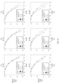
- FIG. 8 is a performance analysis diagram of a data processing method according to this application.
- a horizontal coordinate of the performance analysis diagram is EsN0 and indicates a ratio of energy of each symbol to a noise power spectral density, and a vertical coordinate is a block error rate (block error rate, BLER), used to measure a system performance test.
- block error rate block error rate
- a solid line with a circular symbol, a dashed line with an asterisk, and a dashed line with a square symbol form a group, and may be used to compare differences in decoding performance when decoders with different sizes and different decoding schemes are used for different quantities of information bits.
- the apparatus or the device provided in this application may include a hardware structure and/or a software module, and implement the foregoing functions in a form of the hardware structure, the software module, or a combination of the hardware structure and the software module. Whether a function in the foregoing functions is performed by using the hardware structure, the software module, or the combination of the hardware structure and the software module depends on particular applications and design constraints of the technical solutions. Division into modules in this application is an example, and is merely logical function division. During actual implementation, another division manner may be used.
- functional modules in embodiments of this application may be integrated into one processor, or may exist alone physically, or two or more modules may be integrated into one module.
- the integrated module may be implemented in a form of hardware, or may be implemented in a form of a software functional module.
- FIG. 9 is a diagram of an apparatus according to this application.
- the apparatus may include a one-to-one corresponding module for performing the methods/operations/steps/actions described in the method embodiments corresponding to FIG. 3 to FIG. 7 .
- the module may be a hardware circuit, or may be software, or may be implemented by a combination of a hardware circuit and software.
- the apparatus may be referred to as a data processing apparatus, or may be referred to as a communication apparatus.
- the apparatus includes a communication unit 901 and a processing unit 902, configured to implement the method performed by the terminal device or the network device in the foregoing embodiments.
- the communication unit 901 is configured to obtain K information bits
- the processing unit 902 is configured to determine a length of a to-be-encoded block based on K , and determine a quantity of information bits in each to-be-encoded sub-block in the to-be-encoded block based on the length of the to-be-encoded block and an allocation sequence.
- the allocation sequence is used to describe quantities of information bits in all to-be-encoded sub-blocks except a last to-be-encoded sub-block in the to-be-encoded block in a case of a same code rate and a same to-be-encoded sub-block size.
- the processing unit 902 is configured to encode the to-be-encoded block to obtain encoded data
- the communication unit 901 is configured to send the encoded data.
- processing unit 902 is configured to determine a quantity of information bits in each to-be-encoded sub-block in the to-be-encoded block based on the length of the to-be-encoded block and an allocation sequence may specifically include:
- processing unit 902 is configured to determine a quantity of information bits in each to-be-encoded sub-block in the to-be-encoded block based on the length of the to-be-encoded block and an allocation sequence may specifically include:
- processing unit 902 is configured to encode the to-be-encoded block to obtain encoded data may specifically include:
- the communication unit 901 when sending the encoded data (the encoded data is obtained based on the encoding matrix G ), the communication unit 901 is configured to first send an ( m -1) th to-be-encoded sub-block, and then successively send an i th code sub-block, where i satisfies 0 ⁇ i ⁇ m -2 .
- the communication unit 901 when sending the encoded data (the encoded data is obtained based on the encoding matrix G' ), the communication unit 901 is configured to successively send an i th code sub-block, where i satisfies 0 ⁇ i ⁇ m -1.
- an information bit construction and encoding method based on the allocation sequence is designed.
- the information bit construction method is simple and effective, and helps improve system performance and reduce system power consumption.
- information bit construction and rate matching when a length of a code sub-block is less than an integer multiple of 2 n can be supported in the method.
- the allocation sequence is used to describe quantities of information bits in all to-be-encoded sub-blocks except a last to-be-encoded sub-block in the to-be-encoded block in a case of a same code rate and a same to-be-encoded sub-block size.
- processing unit 902 is configured to decode the encoded data to obtain decoded data may specifically include:
- processing unit 902 is further configured to:
- processing unit 902 is configured to decode the encoded data to obtain decoded data may specifically include:
- processing unit 902 is further configured to:
- the encoded data includes a plurality of code blocks, and quantities of information bits in the plurality of code blocks are designed according to a specific rule.
- stream decoding can be implemented for the encoded data.
- FIG. 10 is a diagram of a communication device according to this application.
- the communication device is configured to implement the data processing methods in the foregoing method embodiments.
- the communication device 1000 may alternatively be a chip system. It may be understood that the communication device 1000 may be, for example, a terminal device, or may be a network device.
- the communication device 1000 includes a communication interface 1001 and a processor 1002.
- the communication interface 1001 may be, for example, a transceiver, an interface, a bus, a circuit, or an apparatus that can implement a receiving function and a sending function.
- the communication interface 1001 is configured to communicate with another device through a transmission medium, so that the device 1000 may communicate with the another device.
- the processor 1002 is configured to perform a processing-related operation.
- the communication interface 1001 is configured to obtain K information bits
- the processor 1002 is configured to determine a length of a to-be-encoded block based on K, and determine a quantity of information bits in each to-be-encoded sub-block in the to-be-encoded block based on the length of the to-be-encoded block and an allocation sequence.
- the allocation sequence is used to describe quantities of information bits in all to-be-encoded sub-blocks except a last to-be-encoded sub-block in the to-be-encoded block in a case of a same code rate and a same to-be-encoded sub-block size.
- the processor 1002 is configured to encode the to-be-encoded block to obtain encoded data
- the communication interface 1001 is configured to send the encoded data.
- an information bit construction and encoding method based on the allocation sequence is designed.
- the information bit construction method is simple and effective, and helps improve system performance and reduce system power consumption.
- information bit construction and rate matching when a length of a code sub-block is less than an integer multiple of 2 n can be supported in the method.
- the communication interface 1001 is configured to receive encoded data
- the processor 1002 is configured to decode the encoded data to obtain decoded data.
- the encoded data is obtained by encoding a to-be-encoded block.
- the to-be-encoded block includes a plurality of to-be-encoded sub-blocks. A quantity of information bits in each to-be-encoded sub-block in the to-be-encoded block is determined based on a length of the to-be-encoded block and an allocation sequence.
- the allocation sequence is used to describe quantities of information bits in all to-be-encoded sub-blocks except a last to-be-encoded sub-block in the to-be-encoded block in a case of a same code rate and a same to-be-encoded sub-block size.
- the encoded data in the data processing method implemented by the communication device includes a plurality of code blocks, and quantities of information bits in the plurality of code blocks are designed according to a specific rule.
- stream decoding can be implemented for the encoded data.
- the communication device 1000 may further include at least one memory 1003, configured to store program instructions and/or data.
- the memory is coupled to the processor.
- the coupling in this application may be an indirect coupling or a communication connection between apparatuses, units, or modules in an electrical form, a mechanical form, or another form, and is used for information exchange between the apparatuses, the units, or the modules.
- the processor may perform an operation in collaboration with the memory.
- the processor may execute the program instructions stored in the memory.
- the at least one memory and the processor are integrated together.
- a specific connection medium between the communication interface, the processor, and the memory is not limited.
- the memory, the processor, and the communication interface are connected through a bus.
- the bus 1004 is represented by a thick line in FIG. 10 .
- a manner of a connection between other components is merely an example for description, and is not construed as a limitation.
- the bus may be classified into an address bus, a data bus, a control bus, and the like. For ease of representation, only one thick line is for representing the bus in FIG. 10 , but this does not mean that there is only one bus or only one type of bus.
- the processor may be a general-purpose processor, a digital signal processor, an application-specific integrated circuit, a field programmable gate array or another programmable logic device, a discrete gate or transistor logic device, or a discrete hardware component, and may implement or perform the methods, steps, and logical block diagrams disclosed in this application.
- the general-purpose processor may be a microprocessor, any conventional processor, or the like. The steps of the methods disclosed with reference to this application may be directly implemented by a hardware processor, or may be implemented by a combination of hardware and a software module in a processor.
- the memory may be a non-volatile memory, for example, a hard disk drive (hard disk drive, HDD) or a solid-state drive (solid-state drive, SSD), or may be a volatile memory (volatile memory), for example, a random access memory (random access memory, RAM).
- the memory is any other medium that can carry or store expected program code in a form of an instruction structure or a data structure and that can be accessed by a computer, but is not limited thereto.
- the memory in this application may be a circuit or any other apparatus that can implement a storage function, and is configured to store program instructions and/or data.
- the communication apparatus includes an input/output interface and a logic circuit.
- the input/output interface is configured to input or output data.
- the logic circuit processes the data according to the methods in the embodiments corresponding to FIG. 3 to FIG. 7 , to obtain processed data.
- the communication apparatus includes an input/output interface and a logic circuit.
- the input/output interface is configured to input or output data.
- the logic circuit processes the data according to the methods in the embodiments corresponding to FIG. 3 to FIG. 7 , to obtain processed data.
- the communication system includes the terminal device and the network device in the embodiments corresponding to FIG. 3 to FIG. 7 .
- This application provides a computer-readable storage medium.
- the computer-readable storage medium stores a program or instructions.
- the program or the instructions are run on a computer, the computer is enabled to perform the data processing methods in the embodiments corresponding to FIG. 3 to FIG. 7 .
- the computer program product includes instructions.
- the instructions When the instructions are run on a computer, the computer is enabled to perform the data processing methods in the embodiments corresponding to FIG. 3 to FIG. 7 .
- the chip or the chip system includes at least one processor and an interface.
- the interface and the at least one processor are interconnected through a line.
- the at least one processor is configured to run a computer program or instructions, to perform the data processing methods in the embodiments corresponding to FIG. 3 to FIG. 7 .
- the interface in the chip may be an input/output interface, a pin, a circuit, or the like.
- the chip system may be a system on chip (system on chip, SoC), or may be a baseband chip, or the like.
- the baseband chip may include a processor, a channel encoder, a digital signal processor, a modem, an interface module, and the like.
- the chip or the chip system described above in this application further includes at least one memory, and the at least one memory stores instructions.
- the memory may be a storage unit inside the chip, for example, a register or a buffer, or may be a storage unit (for example, a read-only memory or a random access memory) of the chip.
- All or some of the technical solutions provided in this application may be implemented by using software, hardware, firmware, or any combination thereof.
- software is used to implement embodiments, all or some of embodiments may be implemented in a form of a computer program product.
- the computer program product includes one or more computer instructions.
- the computer may be a general-purpose computer, a dedicated computer, a computer network, a network device, a terminal device, or another programmable apparatus.
- the computer instructions may be stored in a computer-readable storage medium or may be transmitted from a computer-readable storage medium to another computer-readable storage medium.
- the computer instructions may be transmitted from a website, computer, server, or data center to another website, computer, server, or data center in a wired (for example, a coaxial cable, an optical fiber, or a digital subscriber line (digital subscriber line, DSL)) or wireless (for example, infrared, radio, or microwave) manner.
- the computer-readable storage medium may be any usable medium accessible to the computer, or a data storage device, for example, a server or a data center, integrating one or more usable media.
- the usable medium may be a magnetic medium (for example, a floppy disk, a hard disk, or a magnetic tape), an optical medium (for example, a digital video disc (digital video disc, DVD)), a semiconductor medium, or the like.
- embodiments may be mutually referenced.
- methods and/or terms in the method embodiments may be mutually referenced.
- functions and/or terms in the apparatus embodiments may be mutually referenced.
- functions and/or terms in the apparatus embodiments and the method embodiments may be mutually referenced.
Landscapes
- Engineering & Computer Science (AREA)
- Physics & Mathematics (AREA)
- Theoretical Computer Science (AREA)
- Probability & Statistics with Applications (AREA)
- Signal Processing (AREA)
- Computer Networks & Wireless Communication (AREA)
- Pure & Applied Mathematics (AREA)
- Mathematical Physics (AREA)
- Mathematical Optimization (AREA)
- Mathematical Analysis (AREA)
- General Physics & Mathematics (AREA)
- Computational Mathematics (AREA)
- Algebra (AREA)
- Computing Systems (AREA)
- Compression, Expansion, Code Conversion, And Decoders (AREA)
Applications Claiming Priority (1)
| Application Number | Priority Date | Filing Date | Title |
|---|---|---|---|
| PCT/CN2022/110969 WO2024031287A1 (fr) | 2022-08-08 | 2022-08-08 | Procédé et appareil de traitement de données, et dispositif |
Publications (2)
| Publication Number | Publication Date |
|---|---|
| EP4546730A1 true EP4546730A1 (fr) | 2025-04-30 |
| EP4546730A4 EP4546730A4 (fr) | 2025-08-06 |
Family
ID=89850266
Family Applications (1)
| Application Number | Title | Priority Date | Filing Date |
|---|---|---|---|
| EP22954267.5A Pending EP4546730A4 (fr) | 2022-08-08 | 2022-08-08 | Procédé et appareil de traitement de données, et dispositif |
Country Status (4)
| Country | Link |
|---|---|
| US (1) | US20250167919A1 (fr) |
| EP (1) | EP4546730A4 (fr) |
| CN (1) | CN119605130A (fr) |
| WO (1) | WO2024031287A1 (fr) |
Family Cites Families (8)
| Publication number | Priority date | Publication date | Assignee | Title |
|---|---|---|---|---|
| CN103825669B (zh) * | 2012-11-16 | 2017-10-24 | 华为技术有限公司 | 数据处理的方法和装置 |
| WO2018126496A1 (fr) * | 2017-01-09 | 2018-07-12 | Qualcomm Incorporated | Attribution de bits pour codage et décodage |
| CN108574561B (zh) * | 2017-03-14 | 2020-11-17 | 华为技术有限公司 | 极化码编码的方法和装置 |
| US11411673B2 (en) * | 2018-01-12 | 2022-08-09 | Lg Electronics Inc. | Method and apparatus for transmitting information, and method and apparatus for receiving information |
| US11031958B2 (en) * | 2018-06-25 | 2021-06-08 | Qualcomm Incorporated | Hybrid polar code design for ultra-reliable low latency communications (URLLC) |
| CN113810061B (zh) * | 2020-06-17 | 2025-03-04 | 华为技术有限公司 | Polar码编码方法、Polar码译码方法及其装置 |
| US11513897B2 (en) * | 2020-12-28 | 2022-11-29 | Samsung Electronics Co., Ltd. | Error correction on length-compatible polar codes for memory systems |
| CN114826478A (zh) * | 2021-01-29 | 2022-07-29 | 华为技术有限公司 | 编码调制与解调解码方法及装置 |
-
2022
- 2022-08-08 CN CN202280098388.6A patent/CN119605130A/zh active Pending
- 2022-08-08 WO PCT/CN2022/110969 patent/WO2024031287A1/fr not_active Ceased
- 2022-08-08 EP EP22954267.5A patent/EP4546730A4/fr active Pending
-
2025
- 2025-01-16 US US19/024,061 patent/US20250167919A1/en active Pending
Also Published As
| Publication number | Publication date |
|---|---|
| US20250167919A1 (en) | 2025-05-22 |
| CN119605130A (zh) | 2025-03-11 |
| EP4546730A4 (fr) | 2025-08-06 |
| WO2024031287A1 (fr) | 2024-02-15 |
Similar Documents
| Publication | Publication Date | Title |
|---|---|---|
| CN104038234B (zh) | 极性码的译码方法和译码器 | |
| CN107124188B (zh) | 极化码的编码方法、译码方法、编码设备和译码设备 | |
| CN108347301B (zh) | 数据的传输方法和装置 | |
| CN108462554B (zh) | 一种极性码的传输方法和装置 | |
| US20230283406A1 (en) | Coding method and apparatus | |
| US12463746B2 (en) | Encoding and decoding method and apparatus | |
| CN108282249B (zh) | 一种控制信息的传输方法和装置 | |
| US20250119163A1 (en) | Encoding method and apparatus, decoding method and apparatus, and device | |
| US20230387939A1 (en) | Encoding and decoding method and related apparatus | |
| US11296724B2 (en) | Encoding method and apparatus | |
| US20250167914A1 (en) | Data processing method, apparatus, and device | |
| US10594439B2 (en) | Channel encoding method and apparatus in wireless communications to output a polar encoded bit sequence | |
| US20240405786A1 (en) | Encoding method and encoding apparatus based on polar code | |
| EP4546730A1 (fr) | Procédé et appareil de traitement de données, et dispositif | |
| EP4564684A1 (fr) | Procédé, appareil et dispositif de traitement des données | |
| US11362677B2 (en) | Channel encoding method and encoding apparatus | |
| EP4611323A1 (fr) | Procédé de communication, appareil de communication et système de communication | |
| RU2796655C1 (ru) | Способ кодирования и устройство связи | |
| CN120223242A (zh) | 通信方法、通信装置、存储介质及程序产品 | |
| US20200021395A1 (en) | Channel encoding method and apparatus in wireless communications | |
| CN120017211A (zh) | 极化码编码的方法和装置 | |
| CN120642253A (zh) | 极化码编码的方法和装置 |
Legal Events
| Date | Code | Title | Description |
|---|---|---|---|
| STAA | Information on the status of an ep patent application or granted ep patent |
Free format text: STATUS: THE INTERNATIONAL PUBLICATION HAS BEEN MADE |
|
| PUAI | Public reference made under article 153(3) epc to a published international application that has entered the european phase |
Free format text: ORIGINAL CODE: 0009012 |
|
| STAA | Information on the status of an ep patent application or granted ep patent |
Free format text: STATUS: REQUEST FOR EXAMINATION WAS MADE |
|
| 17P | Request for examination filed |
Effective date: 20250124 |
|
| AK | Designated contracting states |
Kind code of ref document: A1 Designated state(s): AL AT BE BG CH CY CZ DE DK EE ES FI FR GB GR HR HU IE IS IT LI LT LU LV MC MK MT NL NO PL PT RO RS SE SI SK SM TR |
|
| REG | Reference to a national code |
Ref country code: DE Ref legal event code: R079 Free format text: PREVIOUS MAIN CLASS: H04L0027000000 Ipc: H03M0013290000 |
|
| A4 | Supplementary search report drawn up and despatched |
Effective date: 20250704 |
|
| RIC1 | Information provided on ipc code assigned before grant |
Ipc: H03M 13/29 20060101AFI20250630BHEP Ipc: H03M 13/00 20060101ALI20250630BHEP Ipc: H03M 13/13 20060101ALI20250630BHEP Ipc: H04L 1/00 20060101ALI20250630BHEP Ipc: H04L 27/00 20060101ALI20250630BHEP |
|
| DAV | Request for validation of the european patent (deleted) | ||
| DAX | Request for extension of the european patent (deleted) |