EP4546735A2 - Système et procédé de gestion de batterie - Google Patents
Système et procédé de gestion de batterie Download PDFInfo
- Publication number
- EP4546735A2 EP4546735A2 EP25163184.2A EP25163184A EP4546735A2 EP 4546735 A2 EP4546735 A2 EP 4546735A2 EP 25163184 A EP25163184 A EP 25163184A EP 4546735 A2 EP4546735 A2 EP 4546735A2
- Authority
- EP
- European Patent Office
- Prior art keywords
- battery
- level
- management system
- communication
- wireless communication
- Prior art date
- Legal status (The legal status is an assumption and is not a legal conclusion. Google has not performed a legal analysis and makes no representation as to the accuracy of the status listed.)
- Pending
Links
Images




Classifications
-
- H—ELECTRICITY
- H04—ELECTRIC COMMUNICATION TECHNIQUE
- H04L—TRANSMISSION OF DIGITAL INFORMATION, e.g. TELEGRAPHIC COMMUNICATION
- H04L43/00—Arrangements for monitoring or testing data switching networks
- H04L43/08—Monitoring or testing based on specific metrics, e.g. QoS, energy consumption or environmental parameters
- H04L43/0805—Monitoring or testing based on specific metrics, e.g. QoS, energy consumption or environmental parameters by checking availability
- H04L43/0817—Monitoring or testing based on specific metrics, e.g. QoS, energy consumption or environmental parameters by checking availability by checking functioning
-
- H—ELECTRICITY
- H02—GENERATION; CONVERSION OR DISTRIBUTION OF ELECTRIC POWER
- H02J—ELECTRIC POWER NETWORKS; CIRCUIT ARRANGEMENTS OR SYSTEMS FOR SUPPLYING OR DISTRIBUTING ELECTRIC POWER; SYSTEMS FOR STORING ELECTRIC ENERGY
- H02J7/00—Circuit arrangements for charging or discharging batteries or for supplying loads from batteries
- H02J7/40—Circuit arrangements for charging or discharging batteries or for supplying loads from batteries characterised by the exchange of charge or discharge related data
-
- G—PHYSICS
- G01—MEASURING; TESTING
- G01R—MEASURING ELECTRIC VARIABLES; MEASURING MAGNETIC VARIABLES
- G01R31/00—Arrangements for testing electric properties; Arrangements for locating electric faults; Arrangements for electrical testing characterised by what is being tested not provided for elsewhere
- G01R31/36—Arrangements for testing, measuring or monitoring the electrical condition of accumulators or electric batteries, e.g. capacity or state of charge [SoC]
- G01R31/3644—Constructional arrangements
-
- G—PHYSICS
- G01—MEASURING; TESTING
- G01R—MEASURING ELECTRIC VARIABLES; MEASURING MAGNETIC VARIABLES
- G01R31/00—Arrangements for testing electric properties; Arrangements for locating electric faults; Arrangements for electrical testing characterised by what is being tested not provided for elsewhere
- G01R31/36—Arrangements for testing, measuring or monitoring the electrical condition of accumulators or electric batteries, e.g. capacity or state of charge [SoC]
- G01R31/371—Arrangements for testing, measuring or monitoring the electrical condition of accumulators or electric batteries, e.g. capacity or state of charge [SoC] with remote indication, e.g. on external chargers
-
- H—ELECTRICITY
- H01—ELECTRIC ELEMENTS
- H01M—PROCESSES OR MEANS, e.g. BATTERIES, FOR THE DIRECT CONVERSION OF CHEMICAL ENERGY INTO ELECTRICAL ENERGY
- H01M10/00—Secondary cells; Manufacture thereof
- H01M10/42—Methods or arrangements for servicing or maintenance of secondary cells or secondary half-cells
- H01M10/425—Structural combination with electronic components, e.g. electronic circuits integrated to the outside of the casing
-
- H—ELECTRICITY
- H01—ELECTRIC ELEMENTS
- H01M—PROCESSES OR MEANS, e.g. BATTERIES, FOR THE DIRECT CONVERSION OF CHEMICAL ENERGY INTO ELECTRICAL ENERGY
- H01M10/00—Secondary cells; Manufacture thereof
- H01M10/42—Methods or arrangements for servicing or maintenance of secondary cells or secondary half-cells
- H01M10/48—Accumulators combined with arrangements for measuring, testing or indicating the condition of cells, e.g. the level or density of the electrolyte
- H01M10/482—Accumulators combined with arrangements for measuring, testing or indicating the condition of cells, e.g. the level or density of the electrolyte for several batteries or cells simultaneously or sequentially
-
- H—ELECTRICITY
- H04—ELECTRIC COMMUNICATION TECHNIQUE
- H04L—TRANSMISSION OF DIGITAL INFORMATION, e.g. TELEGRAPHIC COMMUNICATION
- H04L12/00—Data switching networks
- H04L12/28—Data switching networks characterised by path configuration, e.g. LAN [Local Area Networks] or WAN [Wide Area Networks]
- H04L12/40—Bus networks
- H04L12/40169—Flexible bus arrangements
- H04L12/40176—Flexible bus arrangements involving redundancy
-
- H—ELECTRICITY
- H04—ELECTRIC COMMUNICATION TECHNIQUE
- H04L—TRANSMISSION OF DIGITAL INFORMATION, e.g. TELEGRAPHIC COMMUNICATION
- H04L12/00—Data switching networks
- H04L12/28—Data switching networks characterised by path configuration, e.g. LAN [Local Area Networks] or WAN [Wide Area Networks]
- H04L12/44—Star or tree networks
-
- H—ELECTRICITY
- H04—ELECTRIC COMMUNICATION TECHNIQUE
- H04L—TRANSMISSION OF DIGITAL INFORMATION, e.g. TELEGRAPHIC COMMUNICATION
- H04L41/00—Arrangements for maintenance, administration or management of data switching networks, e.g. of packet switching networks
- H04L41/06—Management of faults, events, alarms or notifications
- H04L41/0654—Management of faults, events, alarms or notifications using network fault recovery
- H04L41/0668—Management of faults, events, alarms or notifications using network fault recovery by dynamic selection of recovery network elements, e.g. replacement by the most appropriate element after failure
-
- H—ELECTRICITY
- H04—ELECTRIC COMMUNICATION TECHNIQUE
- H04L—TRANSMISSION OF DIGITAL INFORMATION, e.g. TELEGRAPHIC COMMUNICATION
- H04L43/00—Arrangements for monitoring or testing data switching networks
- H04L43/08—Monitoring or testing based on specific metrics, e.g. QoS, energy consumption or environmental parameters
- H04L43/0823—Errors, e.g. transmission errors
-
- H—ELECTRICITY
- H01—ELECTRIC ELEMENTS
- H01M—PROCESSES OR MEANS, e.g. BATTERIES, FOR THE DIRECT CONVERSION OF CHEMICAL ENERGY INTO ELECTRICAL ENERGY
- H01M10/00—Secondary cells; Manufacture thereof
- H01M10/42—Methods or arrangements for servicing or maintenance of secondary cells or secondary half-cells
- H01M10/425—Structural combination with electronic components, e.g. electronic circuits integrated to the outside of the casing
- H01M2010/4271—Battery management systems including electronic circuits, e.g. control of current or voltage to keep battery in healthy state, cell balancing
-
- H—ELECTRICITY
- H01—ELECTRIC ELEMENTS
- H01M—PROCESSES OR MEANS, e.g. BATTERIES, FOR THE DIRECT CONVERSION OF CHEMICAL ENERGY INTO ELECTRICAL ENERGY
- H01M10/00—Secondary cells; Manufacture thereof
- H01M10/42—Methods or arrangements for servicing or maintenance of secondary cells or secondary half-cells
- H01M10/425—Structural combination with electronic components, e.g. electronic circuits integrated to the outside of the casing
- H01M2010/4278—Systems for data transfer from batteries, e.g. transfer of battery parameters to a controller, data transferred between battery controller and main controller
-
- H—ELECTRICITY
- H04—ELECTRIC COMMUNICATION TECHNIQUE
- H04L—TRANSMISSION OF DIGITAL INFORMATION, e.g. TELEGRAPHIC COMMUNICATION
- H04L12/00—Data switching networks
- H04L12/28—Data switching networks characterised by path configuration, e.g. LAN [Local Area Networks] or WAN [Wide Area Networks]
- H04L12/40—Bus networks
-
- H—ELECTRICITY
- H04—ELECTRIC COMMUNICATION TECHNIQUE
- H04L—TRANSMISSION OF DIGITAL INFORMATION, e.g. TELEGRAPHIC COMMUNICATION
- H04L12/00—Data switching networks
- H04L12/28—Data switching networks characterised by path configuration, e.g. LAN [Local Area Networks] or WAN [Wide Area Networks]
- H04L12/40—Bus networks
- H04L2012/40208—Bus networks characterized by the use of a particular bus standard
- H04L2012/40215—Controller Area Network CAN
-
- Y—GENERAL TAGGING OF NEW TECHNOLOGICAL DEVELOPMENTS; GENERAL TAGGING OF CROSS-SECTIONAL TECHNOLOGIES SPANNING OVER SEVERAL SECTIONS OF THE IPC; TECHNICAL SUBJECTS COVERED BY FORMER USPC CROSS-REFERENCE ART COLLECTIONS [XRACs] AND DIGESTS
- Y02—TECHNOLOGIES OR APPLICATIONS FOR MITIGATION OR ADAPTATION AGAINST CLIMATE CHANGE
- Y02E—REDUCTION OF GREENHOUSE GAS [GHG] EMISSIONS, RELATED TO ENERGY GENERATION, TRANSMISSION OR DISTRIBUTION
- Y02E60/00—Enabling technologies; Technologies with a potential or indirect contribution to GHG emissions mitigation
- Y02E60/10—Energy storage using batteries
Definitions
- the present invention relates to a system and method for managing a battery for performing communication with an upper-level controller through other upper-level battery management system when a communication abnormality occurs in an associated upper-level battery management system.
- the secondary battery is a battery capable of charging and discharging, and is meant to include all of a conventional Ni/Cd battery, Ni/MH battery, etc. and a recent lithium ion battery.
- the lithium ion battery has an advantage of having much higher energy density compared to the conventional Ni/Cd battery, Ni/MH battery, etc.
- the lithium ion battery can be manufactured in a small size and light weight, and thus the lithium ion battery is used as a power source for a mobile device.
- the lithium ion battery is attracting attention as a next-generation energy storage medium as its range of use has been expanded to a power source for an electric vehicle.
- a communication structure between the upper-level and lower-level battery management systems should be equipped with an additional interface to perform communication in a mesh structure rather than the tree structure, which has problems such as laying, managing, etc. of additional cables during installation as well as development.
- An object of the present invention is to provide a battery management system and a battery management method that maintain continuity of communication without additional configuration even if a communication abnormality occurs when performing communication in the tree structure between the upper-level and lower-level battery management systems.
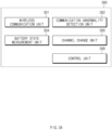
- a system for managing a battery includes a wireless communication unit that communicates with a first upper-level battery management system performing communication using a first communication channel, a communication abnormality detection unit that detects a communication abnormality of the first upper-level battery management system performing communication using the first communication channel, and a channel change unit that changes the communication channel of the wireless communication unit to a second communication channel different from the first communication channel when the communication abnormality of the first upper-level battery management system is detected by the communication abnormality detection unit.
- the communication abnormality detection unit detects a communication abnormality if a signal is not received from the first upper-level battery management system through the first communication channel for a preset time, and the second communication channel is a preset communication channel.
- a plurality of upper-level battery management systems different from the first upper-level battery management system are alternately and periodically connected to and communicate with each other.
- the system for managing the battery further includes a control unit that allows the wireless communication unit to communicate with a second upper-level battery management system connected to the second communication channel when performing communication by changing to the second communication channel and allows a communication abnormality signal of the first upper-level battery management system to be transmitted, through the wireless communication unit, to the second upper-level battery management system through the second communication channel.
- the system for managing the battery further includes a battery state measuring unit that measures a state of the battery, in which the control unit allows measured state-related data of the battery to be transmitted to the second upper-level battery management system through the wireless communication unit.
- a system for managing a battery includes a wireless communication unit that communicates using a plurality of associated lower-level battery management systems disposed in the same battery rack through a third communication channel, a channel change unit that allows the wireless communication unit to communicate using a second communication channel different from the third communication channel for a preset time at a preset period, and a communication unit that transmits and receives data with an upper-level control unit.
- first, second, A, B, (a), and (b) may be used. These terms are only for distinguishing the constituent element from other constituent elements, and the nature, sequence, or order of the component is not limited by the term.
- FIG.1 schematically illustrates a configuration of a plurality of battery racks in an ESS according to an embodiment of the present invention.
- An ESS 15 includes a plurality of battery racks 20, 30, and 40. Each battery rack includes a plurality of battery modules 100 to 110 connected in series or in parallel.
- Each of the battery module 100 to 110 includes a battery management system (BMS) that controls and monitors the battery module.
- BMS battery management system
- the RBMS may transmit a command received from the upper-level system to each battery module or a corresponding battery module.
- the MBMS is a lower-level battery management system of RBMS
- the RBMS is an upper-level battery management system of MBMS.
- Each MBMS monitors the battery status by sensing the temperature, voltage, and current of each battery module or battery cell, and transmits monitored information data to the RBMS in a wireless or wired manner.
- the RBMS that has received battery status information or status information data of the battery module from each MBMS can transmit this data directly to the upper-level controller, or can transmit information data obtained by determining a status of the battery module based on this data to the upper-level controller.
- FIG. 2 schematically illustrates a communication connection between the upper-level battery management system and the lower-level battery management system.
- the battery pack 1 includes a battery module 10 composed of one or more battery cells and capable of charging and discharging, a switching unit 14 connected in series to the +terminal side or the - terminal side of the battery module 10 to control a charge/discharge current flow of the battery module 10, and the MBMS 102 that monitors the voltage, current, temperature, etc. of the battery module 10 and controls and manages to prevent overcharging and overdischarging.
- a battery module 10 composed of one or more battery cells and capable of charging and discharging
- a switching unit 14 connected in series to the +terminal side or the - terminal side of the battery module 10 to control a charge/discharge current flow of the battery module 10, and the MBMS 102 that monitors the voltage, current, temperature, etc. of the battery module 10 and controls and manages to prevent overcharging and overdischarging.
- the switching unit 14 is a semiconductor switching element for controlling the current flow for charging or discharging the battery module 10, and, for example, at least one MOSFET may be used.
- the MBMS 102 can measure or calculate a voltage and current of a gate, source, drain, etc. of the semiconductor switching element in order to monitor a voltage, current, temperature, etc. of the battery module 10, and can also measure the current, voltage, temperature, etc. of the battery module by using a sensor 12 provided adjacent to the semiconductor switching element.
- the MBMS 102 is an interface that receives values obtained by measuring the various parameters described above, and may include a plurality of terminals and a circuit connected to these terminals to perform processing of input values.
- the MBMS 102 can control ON/OFF of the MOSFET, and may be connected to the battery module 10 to monitor the state of the battery module 10.
- the MBMS 102 is connected to an upper-level RBMS 100, and the operation thereof may be controlled based on a signal applied from the upper-level BMS.
- the upper-level RBMS 100 may be connected to the upper-level controller 2.
- the operation of the upper-level RBMS 100 may also be controlled based on a signal applied from the upper-level controller 2.
- FIG. 3A is a configuration diagram of a battery module management system according to an embodiment of the present invention.
- the battery module management systems attempt communication through the second communication channel with any other battery rack management system located in another rack in order to maintain communication continuity.
- each of the battery rack management systems in the plurality of battery racks communicates with the battery module management system in the same rack through a predetermined channel, but periodically performs communication through the second communication channel for a predetermined time.
- Each of the plurality of battery rack management systems alternately performs communication through a second communication channel in each period.
- Each RBMS performs wireless communication with a plurality of MBMSs disposed in each rack.
- Each RBMS wirelessly communicates with each of the plurality of MBMSs disposed in each rack through each set communication channel.
- the battery module management system 300 transmits a communication abnormality signal of the first upper-level battery management system to the second upper-level battery management system performing communication using the second communication channel (S504).
- the second upper-level battery management system is a battery rack management system which is performing communication through the second communication channel when the battery module management system 300 performs communication using the second communication channel.
- the battery module management system 300 communicates with the second upper-level battery management system through the second communication channel (S506).
- the wireless communication unit 301 transmits the battery status data to the second battery rack management system through the second communication channel.
- the wireless communication unit 301 receives various commands received from the upper-level controller from the second battery rack management system through the second communication channel.
- FIG. 6 is a flowchart of a method for managing a battery according to an embodiment of the present invention.
- the battery rack management system 309 communicates with a lower-level battery management system, which is a battery module management system in the same rack, through a third communication channel (S600).
- the wireless communication unit 310 of the battery rack management system typically performs wireless communication with the battery module management system in the same rack through a preset communication channel, for example, a third communication channel.
- the wireless communication unit 310 transmits commands received from an upper-level controller to a battery module in the same battery rack through the third communication channel.
- the battery rack management system 309 performs communication through a preset second communication channel for a preset time at a preset period (S602).
- the wireless communication unit 310 of the battery rack management system 309 performs communication through the second communication channel which is the preset communication channel for a predetermined time at a preset period.
- the battery rack management system 309 receives a communication abnormality signal of the first upper-level battery management system from a lower-level battery system in another rack while performing communication through the second communication channel, the communication abnormality signal is transmitted to the upper-level controller (S604).
- the wireless communication unit 310 can perform communication with the battery module management system 300 in the corresponding rack and receives the communication abnormality signal of the battery rack management system in the corresponding rack from the battery module management system 300 through the second communication channel.
- the battery rack management system 309 transmits the battery status data received from the lower-level battery management system to the upper-level controller through the second communication channel (S606).
- the wireless communication unit 310 of the battery rack management system 309 can receive battery status information data from the battery module management system 300 in the rack in which the communication abnormality has occurred through the second communication channel.
- the battery rack management system 309 transmits the command received from the upper-level controller from before a predetermined time to the battery module management system, which is a lower-level battery management system, through the second communication channel (S608)
- the wireless communication unit 310 of the battery rack management system 309 transmits corresponding commands to the battery module management system 300 through the second communication channel.
- FIG. 7 is a block diagram illustrating a hardware configuration of the system for managing the battery according to the embodiment of the present invention.
- a system 700 for managing a battery may include a microcontroller (MCU) 710 that controls various processes and configurations, a memory 720 in which an operating system program and various programs (e.g., a battery pack abnormality diagnosis program or a battery pack temperature estimation program), etc. are recorded, an input and output interface 730 that provides an input interface and an output interface between the battery cell module and/or the semiconductor switching element, and a communication interface 740 capable of performing communication with the outside through a wired or wireless communication network.
- the computer program according to the present invention is recorded in the memory 720 and processed by the microcontroller 710, thereby capable of being implemented as a module that performs the respective functional blocks illustrated in FIGS. 3A and 3B .
Landscapes
- Engineering & Computer Science (AREA)
- Computer Networks & Wireless Communication (AREA)
- Signal Processing (AREA)
- Environmental & Geological Engineering (AREA)
- Manufacturing & Machinery (AREA)
- Chemical & Material Sciences (AREA)
- Chemical Kinetics & Catalysis (AREA)
- Electrochemistry (AREA)
- General Chemical & Material Sciences (AREA)
- Physics & Mathematics (AREA)
- General Physics & Mathematics (AREA)
- Power Engineering (AREA)
- Microelectronics & Electronic Packaging (AREA)
- Charge And Discharge Circuits For Batteries Or The Like (AREA)
- Secondary Cells (AREA)
- Tests Of Electric Status Of Batteries (AREA)
- Mobile Radio Communication Systems (AREA)
Applications Claiming Priority (4)
| Application Number | Priority Date | Filing Date | Title |
|---|---|---|---|
| KR1020190080269A KR102679115B1 (ko) | 2019-07-03 | 2019-07-03 | 배터리 관리 시스템 및 관리 방법 |
| PCT/KR2020/008546 WO2021002658A1 (fr) | 2019-07-03 | 2020-06-30 | Système de gestion de batterie et procédé de gestion |
| EP20834303.8A EP3972198B1 (fr) | 2019-07-03 | 2020-06-30 | Système de gestion de batterie et procédé de gestion |
| EP23186553.6A EP4236236B1 (fr) | 2019-07-03 | 2020-06-30 | Système de gestion de batterie et procédé de gestion |
Related Parent Applications (3)
| Application Number | Title | Priority Date | Filing Date |
|---|---|---|---|
| EP23186553.6A Division EP4236236B1 (fr) | 2019-07-03 | 2020-06-30 | Système de gestion de batterie et procédé de gestion |
| EP23186553.6A Division-Into EP4236236B1 (fr) | 2019-07-03 | 2020-06-30 | Système de gestion de batterie et procédé de gestion |
| EP20834303.8A Division EP3972198B1 (fr) | 2019-07-03 | 2020-06-30 | Système de gestion de batterie et procédé de gestion |
Publications (2)
| Publication Number | Publication Date |
|---|---|
| EP4546735A2 true EP4546735A2 (fr) | 2025-04-30 |
| EP4546735A3 EP4546735A3 (fr) | 2025-08-06 |
Family
ID=74100227
Family Applications (3)
| Application Number | Title | Priority Date | Filing Date |
|---|---|---|---|
| EP23186553.6A Active EP4236236B1 (fr) | 2019-07-03 | 2020-06-30 | Système de gestion de batterie et procédé de gestion |
| EP20834303.8A Active EP3972198B1 (fr) | 2019-07-03 | 2020-06-30 | Système de gestion de batterie et procédé de gestion |
| EP25163184.2A Pending EP4546735A3 (fr) | 2019-07-03 | 2020-06-30 | Système et procédé de gestion de batterie |
Family Applications Before (2)
| Application Number | Title | Priority Date | Filing Date |
|---|---|---|---|
| EP23186553.6A Active EP4236236B1 (fr) | 2019-07-03 | 2020-06-30 | Système de gestion de batterie et procédé de gestion |
| EP20834303.8A Active EP3972198B1 (fr) | 2019-07-03 | 2020-06-30 | Système de gestion de batterie et procédé de gestion |
Country Status (7)
| Country | Link |
|---|---|
| US (2) | US12218530B2 (fr) |
| EP (3) | EP4236236B1 (fr) |
| JP (1) | JP7278428B2 (fr) |
| KR (1) | KR102679115B1 (fr) |
| ES (2) | ES3031711T3 (fr) |
| HU (2) | HUE071665T2 (fr) |
| WO (1) | WO2021002658A1 (fr) |
Families Citing this family (13)
| Publication number | Priority date | Publication date | Assignee | Title |
|---|---|---|---|---|
| KR102743585B1 (ko) * | 2019-09-09 | 2024-12-17 | 주식회사 엘지에너지솔루션 | 중간 노드를 이용하여 통신하는 배터리 관리 시스템 및 방법 |
| KR102325445B1 (ko) * | 2021-04-28 | 2021-12-01 | 주식회사 네오세미텍 | 배터리팩 및 배터리팩 관리 시스템 |
| CN113442793A (zh) * | 2021-05-27 | 2021-09-28 | 苏州艾比柯电子有限公司 | 一种锂电池组智能监控系统及方法 |
| AU2023209310A1 (en) * | 2022-01-19 | 2024-04-11 | Lg Energy Solution, Ltd. | Energy storage system |
| WO2023206507A1 (fr) * | 2022-04-29 | 2023-11-02 | 时代电服科技有限公司 | Procédé et appareil de commande de connexion sans fil pour dispositif de gestion de batterie et dispositif de gestion de batterie |
| CN114977427B (zh) * | 2022-06-28 | 2026-02-10 | 珠海冠宇电源有限公司 | 通信控制方法、装置、终端设备及存储介质 |
| EP4415209B1 (fr) * | 2022-09-27 | 2025-12-17 | LG Energy Solution, Ltd. | Dispositif de commande de batterie pour répondre à une perte de situation de communication, et système de stockage d'énergie comprenant celui-ci |
| EP4414730B1 (fr) * | 2022-09-27 | 2026-04-22 | LG Energy Solution, Ltd. | Système de stockage d'énergie pour réagir à une situation de communication anormale et son procédé associé |
| KR20250049870A (ko) * | 2023-10-05 | 2025-04-14 | 주식회사 엘지에너지솔루션 | 데이터 처리 장치 및 그것의 동작 방법 |
| CN117395684A (zh) * | 2023-10-26 | 2024-01-12 | 欣旺达动力科技股份有限公司 | 一种自适应最优信道无线通讯电池管理系统及方法 |
| KR20250071684A (ko) * | 2023-11-15 | 2025-05-22 | 주식회사 엘지에너지솔루션 | 통신 상태를 점검하는 방법 및 이를 수행하는 배터리 관리 시스템 |
| DE102023213166B3 (de) * | 2023-12-21 | 2025-06-26 | Schaeffler Technologies AG & Co. KG | Verfahren zum Ermitteln einer Einbauposition eines Batteriemoduls in einer Batterie |
| CN117930028B (zh) * | 2024-03-21 | 2024-05-17 | 成都赛力斯科技有限公司 | 新能源车辆电池热失效的预测方法、系统、设备及介质 |
Family Cites Families (17)
| Publication number | Priority date | Publication date | Assignee | Title |
|---|---|---|---|---|
| JPS5734690A (en) * | 1980-08-11 | 1982-02-25 | Matsushita Electric Industrial Co Ltd | Method of producing sheathed heater |
| KR101514660B1 (ko) | 2010-03-03 | 2015-04-24 | 배명한 | 배터리 관리시스템 및 이를 이용한 서비스 제공방법 |
| CN103270666B (zh) | 2010-11-02 | 2018-01-30 | 纳维达斯解决方案有限公司 | 用于智能电池管理的无线电池区域网络 |
| US9559530B2 (en) | 2010-11-02 | 2017-01-31 | Navitas Solutions | Fault tolerant wireless battery area network for a smart battery management system |
| US9564762B2 (en) * | 2010-11-02 | 2017-02-07 | Navitas Solutions | Fault tolerant wireless battery area network for a smart battery management system |
| JP5537468B2 (ja) | 2011-03-01 | 2014-07-02 | 株式会社日立製作所 | 蓄電池制御システムおよび蓄電池制御方法 |
| CN104885326B (zh) | 2012-12-28 | 2017-06-13 | 日立麦克赛尔株式会社 | 组合电池系统、蓄电池系统以及组合电池系统的监视控制方法 |
| US10193190B2 (en) * | 2013-11-01 | 2019-01-29 | Hitachi, Ltd. | Battery control system |
| WO2015189898A1 (fr) | 2014-06-09 | 2015-12-17 | 日立オートモティブシステムズ株式会社 | Système de batteries |
| JP6194857B2 (ja) | 2014-06-27 | 2017-09-13 | 日立化成株式会社 | 電池システム |
| KR20160019237A (ko) | 2014-08-11 | 2016-02-19 | 조주현 | 배터리 방전 제어방법 및 장치 |
| KR101726930B1 (ko) | 2014-12-08 | 2017-04-13 | 주식회사 엘지화학 | 배터리 관리 시스템 간의 통신 시스템 및 통신을 위한 연결 방법 |
| KR101641435B1 (ko) | 2014-12-16 | 2016-07-20 | 중소기업은행 | 배터리 관리 시스템 및 이를 탑재한 전기자동차 |
| KR101749390B1 (ko) | 2015-01-28 | 2017-06-20 | 주식회사 엘지화학 | 캔 통신 시스템 및 캔 통신 장치 |
| KR101588664B1 (ko) | 2015-09-22 | 2016-01-25 | 주식회사 대영 | 중앙제어전용통합입출력수단을 이용한 원클릭 수리시설관리 자동화시스템 |
| JP6494567B2 (ja) | 2016-06-27 | 2019-04-03 | 矢崎総業株式会社 | 通信管理装置および通信システム |
| KR102273770B1 (ko) | 2016-07-19 | 2021-07-06 | 삼성에스디아이 주식회사 | 배터리 시스템 |
-
2019
- 2019-07-03 KR KR1020190080269A patent/KR102679115B1/ko active Active
-
2020
- 2020-06-30 US US17/615,955 patent/US12218530B2/en active Active
- 2020-06-30 HU HUE23186553A patent/HUE071665T2/hu unknown
- 2020-06-30 EP EP23186553.6A patent/EP4236236B1/fr active Active
- 2020-06-30 WO PCT/KR2020/008546 patent/WO2021002658A1/fr not_active Ceased
- 2020-06-30 JP JP2021572056A patent/JP7278428B2/ja active Active
- 2020-06-30 HU HUE20834303A patent/HUE064877T2/hu unknown
- 2020-06-30 ES ES23186553T patent/ES3031711T3/es active Active
- 2020-06-30 EP EP20834303.8A patent/EP3972198B1/fr active Active
- 2020-06-30 ES ES20834303T patent/ES2969495T3/es active Active
- 2020-06-30 EP EP25163184.2A patent/EP4546735A3/fr active Pending
-
2024
- 2024-12-31 US US19/007,140 patent/US20250141239A1/en active Pending
Also Published As
| Publication number | Publication date |
|---|---|
| JP7278428B2 (ja) | 2023-05-19 |
| EP4236236A3 (fr) | 2023-11-01 |
| EP3972198A1 (fr) | 2022-03-23 |
| JP2022535123A (ja) | 2022-08-04 |
| WO2021002658A1 (fr) | 2021-01-07 |
| KR102679115B1 (ko) | 2024-06-28 |
| HUE071665T2 (hu) | 2025-09-28 |
| ES2969495T3 (es) | 2024-05-20 |
| ES3031711T3 (en) | 2025-07-10 |
| EP4236236A2 (fr) | 2023-08-30 |
| EP3972198A4 (fr) | 2022-08-03 |
| EP3972198B1 (fr) | 2023-12-20 |
| HUE064877T2 (hu) | 2024-04-28 |
| US20250141239A1 (en) | 2025-05-01 |
| US20220329086A1 (en) | 2022-10-13 |
| KR20210004216A (ko) | 2021-01-13 |
| EP4236236B1 (fr) | 2025-04-30 |
| US12218530B2 (en) | 2025-02-04 |
| EP4546735A3 (fr) | 2025-08-06 |
Similar Documents
| Publication | Publication Date | Title |
|---|---|---|
| EP3972198B1 (fr) | Système de gestion de batterie et procédé de gestion | |
| US11965936B2 (en) | Battery diagnosis apparatus and method | |
| JP7517771B2 (ja) | マスターバッテリー管理システムおよびスレーブバッテリー管理システム | |
| EP3961233A1 (fr) | Dispositif et procédé de diagnostic de cellule de batterie | |
| EP3974850B1 (fr) | Dispositif et procédé de diagnostic de relais de batterie parallèle | |
| KR102809159B1 (ko) | 전류 센서 진단 장치 및 이를 포함하는 배터리 팩 | |
| EP4016099B1 (fr) | Appareil et procédé de diagnostic de batterie | |
| KR20210069916A (ko) | 배터리 관리 장치 및 배터리 이중 관리 시스템 | |
| KR102930305B1 (ko) | 배터리 팩 및 그것의 동작 방법 | |
| KR20210022470A (ko) | 배터리 관리 시스템 및 배터리 관리 방법 | |
| CN118800982A (zh) | 电池系统和电池系统的监测方法 | |
| KR20210017910A (ko) | 배터리 관리 시스템 및 배터리 관리 방법 | |
| KR20210137624A (ko) | 배터리 충방전 제어 장치 및 배터리 관리 장치 |
Legal Events
| Date | Code | Title | Description |
|---|---|---|---|
| PUAI | Public reference made under article 153(3) epc to a published international application that has entered the european phase |
Free format text: ORIGINAL CODE: 0009012 |
|
| STAA | Information on the status of an ep patent application or granted ep patent |
Free format text: STATUS: REQUEST FOR EXAMINATION WAS MADE |
|
| 17P | Request for examination filed |
Effective date: 20250312 |
|
| AC | Divisional application: reference to earlier application |
Ref document number: 3972198 Country of ref document: EP Kind code of ref document: P Ref document number: 4236236 Country of ref document: EP Kind code of ref document: P |
|
| AK | Designated contracting states |
Kind code of ref document: A2 Designated state(s): AL AT BE BG CH CY CZ DE DK EE ES FI FR GB GR HR HU IE IS IT LI LT LU LV MC MK MT NL NO PL PT RO RS SE SI SK SM TR |
|
| REG | Reference to a national code |
Ref country code: DE Ref legal event code: R079 Free format text: PREVIOUS MAIN CLASS: H04L0041066800 Ipc: H04L0012440000 |
|
| PUAL | Search report despatched |
Free format text: ORIGINAL CODE: 0009013 |
|
| AK | Designated contracting states |
Kind code of ref document: A3 Designated state(s): AL AT BE BG CH CY CZ DE DK EE ES FI FR GB GR HR HU IE IS IT LI LT LU LV MC MK MT NL NO PL PT RO RS SE SI SK SM TR |
|
| RIC1 | Information provided on ipc code assigned before grant |
Ipc: H04L 12/44 20060101AFI20250630BHEP Ipc: H02J 7/00 20060101ALI20250630BHEP Ipc: H04L 12/40 20060101ALI20250630BHEP Ipc: H04L 41/0668 20220101ALI20250630BHEP |
|
| GRAP | Despatch of communication of intention to grant a patent |
Free format text: ORIGINAL CODE: EPIDOSNIGR1 |
|
| STAA | Information on the status of an ep patent application or granted ep patent |
Free format text: STATUS: GRANT OF PATENT IS INTENDED |
|
| INTG | Intention to grant announced |
Effective date: 20260305 |