EP4548794A1 - Semelle comprenant un cadre de renfort - Google Patents
Semelle comprenant un cadre de renfort Download PDFInfo
- Publication number
- EP4548794A1 EP4548794A1 EP24207165.2A EP24207165A EP4548794A1 EP 4548794 A1 EP4548794 A1 EP 4548794A1 EP 24207165 A EP24207165 A EP 24207165A EP 4548794 A1 EP4548794 A1 EP 4548794A1
- Authority
- EP
- European Patent Office
- Prior art keywords
- sole
- reinforcing frame
- midsole
- shoe
- heel
- Prior art date
- Legal status (The legal status is an assumption and is not a legal conclusion. Google has not performed a legal analysis and makes no representation as to the accuracy of the status listed.)
- Pending
Links
- 230000003014 reinforcing effect Effects 0.000 title claims abstract description 263
- 239000000463 material Substances 0.000 claims description 75
- 210000000452 mid-foot Anatomy 0.000 claims description 58
- 239000006261 foam material Substances 0.000 claims description 18
- 239000004952 Polyamide Substances 0.000 claims description 17
- 229920002647 polyamide Polymers 0.000 claims description 17
- 239000004433 Thermoplastic polyurethane Substances 0.000 claims description 13
- 229920002803 thermoplastic polyurethane Polymers 0.000 claims description 13
- 239000002131 composite material Substances 0.000 claims description 9
- 229920000049 Carbon (fiber) Polymers 0.000 claims description 8
- 239000004917 carbon fiber Substances 0.000 claims description 8
- 239000005038 ethylene vinyl acetate Substances 0.000 claims description 8
- 229920001200 poly(ethylene-vinyl acetate) Polymers 0.000 claims description 5
- 239000004677 Nylon Substances 0.000 claims description 4
- DQXBYHZEEUGOBF-UHFFFAOYSA-N but-3-enoic acid;ethene Chemical compound C=C.OC(=O)CC=C DQXBYHZEEUGOBF-UHFFFAOYSA-N 0.000 claims description 4
- 239000003365 glass fiber Substances 0.000 claims description 4
- VNWKTOKETHGBQD-UHFFFAOYSA-N methane Chemical compound C VNWKTOKETHGBQD-UHFFFAOYSA-N 0.000 claims description 4
- 229920001778 nylon Polymers 0.000 claims description 4
- 210000000474 heel Anatomy 0.000 description 105
- 210000003371 toe Anatomy 0.000 description 98
- 230000008901 benefit Effects 0.000 description 66
- 239000006260 foam Substances 0.000 description 50
- 210000002683 foot Anatomy 0.000 description 42
- 239000002245 particle Substances 0.000 description 34
- 230000000386 athletic effect Effects 0.000 description 19
- 210000004744 fore-foot Anatomy 0.000 description 15
- RTZKZFJDLAIYFH-UHFFFAOYSA-N Diethyl ether Chemical compound CCOCC RTZKZFJDLAIYFH-UHFFFAOYSA-N 0.000 description 14
- 238000000034 method Methods 0.000 description 13
- 229920000642 polymer Polymers 0.000 description 13
- 239000011324 bead Substances 0.000 description 12
- 229920002614 Polyether block amide Polymers 0.000 description 11
- -1 polyethylene terephthalate Polymers 0.000 description 11
- 229920005983 Infinergy® Polymers 0.000 description 10
- 230000000694 effects Effects 0.000 description 10
- 239000000853 adhesive Substances 0.000 description 9
- 230000001070 adhesive effect Effects 0.000 description 9
- 229920001971 elastomer Polymers 0.000 description 9
- 239000000806 elastomer Substances 0.000 description 7
- 230000006870 function Effects 0.000 description 7
- 230000005021 gait Effects 0.000 description 7
- 229920001707 polybutylene terephthalate Polymers 0.000 description 7
- 229920000728 polyester Polymers 0.000 description 7
- 239000005020 polyethylene terephthalate Substances 0.000 description 7
- 230000000087 stabilizing effect Effects 0.000 description 7
- 229920001169 thermoplastic Polymers 0.000 description 7
- 239000004416 thermosoftening plastic Substances 0.000 description 7
- 238000010276 construction Methods 0.000 description 6
- 210000001255 hallux Anatomy 0.000 description 6
- 229920000139 polyethylene terephthalate Polymers 0.000 description 6
- 230000001771 impaired effect Effects 0.000 description 5
- 238000004519 manufacturing process Methods 0.000 description 5
- 230000035939 shock Effects 0.000 description 5
- 230000009286 beneficial effect Effects 0.000 description 4
- 210000003850 cellular structure Anatomy 0.000 description 4
- 238000013037 co-molding Methods 0.000 description 4
- 230000007423 decrease Effects 0.000 description 4
- 238000013461 design Methods 0.000 description 4
- 210000000454 fifth toe Anatomy 0.000 description 4
- 238000005187 foaming Methods 0.000 description 4
- 239000000203 mixture Substances 0.000 description 4
- 238000010521 absorption reaction Methods 0.000 description 3
- 230000002411 adverse Effects 0.000 description 3
- 210000003423 ankle Anatomy 0.000 description 3
- 230000001627 detrimental effect Effects 0.000 description 3
- 235000019589 hardness Nutrition 0.000 description 3
- 230000006872 improvement Effects 0.000 description 3
- 230000001788 irregular Effects 0.000 description 3
- 210000001872 metatarsal bone Anatomy 0.000 description 3
- 230000008450 motivation Effects 0.000 description 3
- 229920000747 poly(lactic acid) Polymers 0.000 description 3
- 230000008569 process Effects 0.000 description 3
- 230000002787 reinforcement Effects 0.000 description 3
- 239000000243 solution Substances 0.000 description 3
- 239000004604 Blowing Agent Substances 0.000 description 2
- 208000027418 Wounds and injury Diseases 0.000 description 2
- 230000006978 adaptation Effects 0.000 description 2
- 230000006378 damage Effects 0.000 description 2
- 230000007812 deficiency Effects 0.000 description 2
- 238000009826 distribution Methods 0.000 description 2
- 238000001746 injection moulding Methods 0.000 description 2
- 208000014674 injury Diseases 0.000 description 2
- 230000002045 lasting effect Effects 0.000 description 2
- 239000007788 liquid Substances 0.000 description 2
- 239000004814 polyurethane Substances 0.000 description 2
- 230000001141 propulsive effect Effects 0.000 description 2
- 230000004044 response Effects 0.000 description 2
- 239000005060 rubber Substances 0.000 description 2
- 210000004243 sweat Anatomy 0.000 description 2
- 239000012815 thermoplastic material Substances 0.000 description 2
- 238000012549 training Methods 0.000 description 2
- 235000009854 Cucurbita moschata Nutrition 0.000 description 1
- 240000001980 Cucurbita pepo Species 0.000 description 1
- 235000009852 Cucurbita pepo Nutrition 0.000 description 1
- 229920002430 Fibre-reinforced plastic Polymers 0.000 description 1
- 238000009825 accumulation Methods 0.000 description 1
- 238000004026 adhesive bonding Methods 0.000 description 1
- 238000005452 bending Methods 0.000 description 1
- 230000005540 biological transmission Effects 0.000 description 1
- 210000000988 bone and bone Anatomy 0.000 description 1
- 210000000459 calcaneus Anatomy 0.000 description 1
- 239000004568 cement Substances 0.000 description 1
- 230000008859 change Effects 0.000 description 1
- 230000009194 climbing Effects 0.000 description 1
- 230000001427 coherent effect Effects 0.000 description 1
- 230000000295 complement effect Effects 0.000 description 1
- 238000002788 crimping Methods 0.000 description 1
- 230000001351 cycling effect Effects 0.000 description 1
- 230000001419 dependent effect Effects 0.000 description 1
- 230000003467 diminishing effect Effects 0.000 description 1
- 230000009977 dual effect Effects 0.000 description 1
- 210000003195 fascia Anatomy 0.000 description 1
- 239000000835 fiber Substances 0.000 description 1
- 239000011151 fibre-reinforced plastic Substances 0.000 description 1
- 210000000497 foam cell Anatomy 0.000 description 1
- 230000004927 fusion Effects 0.000 description 1
- 239000007789 gas Substances 0.000 description 1
- 230000003116 impacting effect Effects 0.000 description 1
- 238000002347 injection Methods 0.000 description 1
- 239000007924 injection Substances 0.000 description 1
- 238000009413 insulation Methods 0.000 description 1
- 230000002452 interceptive effect Effects 0.000 description 1
- 239000002184 metal Substances 0.000 description 1
- 239000012768 molten material Substances 0.000 description 1
- 238000000465 moulding Methods 0.000 description 1
- 210000003205 muscle Anatomy 0.000 description 1
- 238000013021 overheating Methods 0.000 description 1
- 239000008188 pellet Substances 0.000 description 1
- 229920003023 plastic Polymers 0.000 description 1
- 239000004033 plastic Substances 0.000 description 1
- 230000009467 reduction Effects 0.000 description 1
- 230000001105 regulatory effect Effects 0.000 description 1
- 238000000926 separation method Methods 0.000 description 1
- 238000009958 sewing Methods 0.000 description 1
- 238000007493 shaping process Methods 0.000 description 1
- 238000010008 shearing Methods 0.000 description 1
- 239000011359 shock absorbing material Substances 0.000 description 1
- 238000009751 slip forming Methods 0.000 description 1
- 239000011343 solid material Substances 0.000 description 1
- 230000009192 sprinting Effects 0.000 description 1
- 235000020354 squash Nutrition 0.000 description 1
- 239000000126 substance Substances 0.000 description 1
- 230000002195 synergetic effect Effects 0.000 description 1
- 235000019587 texture Nutrition 0.000 description 1
- 238000012546 transfer Methods 0.000 description 1
- 230000000007 visual effect Effects 0.000 description 1
- 238000004073 vulcanization Methods 0.000 description 1
- XLYOFNOQVPJJNP-UHFFFAOYSA-N water Substances O XLYOFNOQVPJJNP-UHFFFAOYSA-N 0.000 description 1
Images


Classifications
-
- A—HUMAN NECESSITIES
- A43—FOOTWEAR
- A43B—CHARACTERISTIC FEATURES OF FOOTWEAR; PARTS OF FOOTWEAR
- A43B7/00—Footwear with health or hygienic arrangements
- A43B7/32—Footwear with health or hygienic arrangements with shock-absorbing means
-
- A—HUMAN NECESSITIES
- A43—FOOTWEAR
- A43B—CHARACTERISTIC FEATURES OF FOOTWEAR; PARTS OF FOOTWEAR
- A43B13/00—Soles; Sole-and-heel integral units
- A43B13/02—Soles; Sole-and-heel integral units characterised by the material
- A43B13/12—Soles with several layers of different materials
- A43B13/125—Soles with several layers of different materials characterised by the midsole or middle layer
- A43B13/127—Soles with several layers of different materials characterised by the midsole or middle layer the midsole being multilayer
-
- A—HUMAN NECESSITIES
- A43—FOOTWEAR
- A43B—CHARACTERISTIC FEATURES OF FOOTWEAR; PARTS OF FOOTWEAR
- A43B13/00—Soles; Sole-and-heel integral units
- A43B13/02—Soles; Sole-and-heel integral units characterised by the material
- A43B13/026—Composites, e.g. carbon fibre or aramid fibre; the sole, one or more sole layers or sole part being made of a composite
-
- A—HUMAN NECESSITIES
- A43—FOOTWEAR
- A43B—CHARACTERISTIC FEATURES OF FOOTWEAR; PARTS OF FOOTWEAR
- A43B13/00—Soles; Sole-and-heel integral units
- A43B13/02—Soles; Sole-and-heel integral units characterised by the material
- A43B13/04—Plastics, rubber or vulcanised fibre
-
- A—HUMAN NECESSITIES
- A43—FOOTWEAR
- A43B—CHARACTERISTIC FEATURES OF FOOTWEAR; PARTS OF FOOTWEAR
- A43B13/00—Soles; Sole-and-heel integral units
- A43B13/02—Soles; Sole-and-heel integral units characterised by the material
- A43B13/12—Soles with several layers of different materials
- A43B13/125—Soles with several layers of different materials characterised by the midsole or middle layer
-
- A—HUMAN NECESSITIES
- A43—FOOTWEAR
- A43B—CHARACTERISTIC FEATURES OF FOOTWEAR; PARTS OF FOOTWEAR
- A43B13/00—Soles; Sole-and-heel integral units
- A43B13/14—Soles; Sole-and-heel integral units characterised by the constructive form
-
- A—HUMAN NECESSITIES
- A43—FOOTWEAR
- A43B—CHARACTERISTIC FEATURES OF FOOTWEAR; PARTS OF FOOTWEAR
- A43B13/00—Soles; Sole-and-heel integral units
- A43B13/14—Soles; Sole-and-heel integral units characterised by the constructive form
- A43B13/143—Soles; Sole-and-heel integral units characterised by the constructive form provided with wedged, concave or convex end portions, e.g. for improving roll-off of the foot
- A43B13/145—Convex portions, e.g. with a bump or projection, e.g. 'Masai' type shoes
-
- A—HUMAN NECESSITIES
- A43—FOOTWEAR
- A43B—CHARACTERISTIC FEATURES OF FOOTWEAR; PARTS OF FOOTWEAR
- A43B13/00—Soles; Sole-and-heel integral units
- A43B13/14—Soles; Sole-and-heel integral units characterised by the constructive form
- A43B13/18—Resilient soles
- A43B13/181—Resiliency achieved by the structure of the sole
- A43B13/185—Elasticated plates sandwiched between two interlocking components, e.g. thrustors
-
- A—HUMAN NECESSITIES
- A43—FOOTWEAR
- A43B—CHARACTERISTIC FEATURES OF FOOTWEAR; PARTS OF FOOTWEAR
- A43B5/00—Footwear for sporting purposes
- A43B5/06—Running shoes; Track shoes
Definitions
- the present disclosure relates to a sole for a shoe, in particular for a sports shoe, such as a running shoe.
- the present disclosure also relates to a shoe, in particular a sports shoe, such as a running shoe, comprising such a sole.
- Soles for shoes in particular soles for sports shoes, such as running shoes are generally known and have various purposes and use cases.
- a shoe sole typically serves a number of different functions, such as diminishing or cushioning of the impact forces occurring upon foot strike and providing traction to avoid slipping of the wearer's foot.
- a shoe sole typically serves the function to provide a degree of stability to the wearer's foot, so that the danger of twisting one's ankle or other kinds of injuries, for example injury to the plantar fascia or muscle overloading, etc., can be reduced.
- Yet a further function of a shoe sole, particularly for performance footwear like running shoes is to facilitate a good transmission of forces from the athlete's legs through their feet to the ground and an efficient running style, in order to improve the athlete's performance.
- a sole for a shoe that enables a safer running, supports the wearer during longer distances, reveals a high degree of cushioning, provides a large energy return to the wearer, and that is light weight.
- Prior art document EP 3 868 242 A2 relates to a sole for a shoe, in particular a running shoe, which comprises at least two reinforcing members extending in a front half of the sole, wherein at least a first one of the reinforcing members further extends rearwardly beyond the midfoot area and into a heel area of the sole and wraps up to a posterior portion of the ankle region.
- Prior art document US 10 842 224 B2 relates to a plate for an article of footwear having a sole structure that includes an anterior-most point disposed in a forefoot region of the sole structure, a posterior-most point disposed closer to a heel region of the sole structure than the anterior-most point, and a concave portion extending between the anterior-most point and the posterior-most point.
- the concave portion includes a constant radius of curvature from the anterior-most point to a metatarsophalangeal (MTP) point of the sole structure.
- MTP metatarsophalangeal
- Prior art document EP 10 024 73 B1 relates to a device for increasing the movement stability of shoes for tennis or similar sports, comprising a plate-like support which is substantially Y-shaped and has a first curved portion, which is adapted to follow the profile of the heel region, and a second portion, which is adapted to follow the outer profile of the foot. The second portion widens transversely with a third portion so as to affect the inner metatarsal region of the foot.
- the support is coupled in a downward region to a mid-sole made of shock-absorbing material in order to distribute thereon the load transmitted by the moving foot.
- Prior art document KR 10 2 097 381 B1 relates to a shoe sole having functions of shock absorption and walking impetus, and a shoe comprising the same.
- the document discloses a first midsole supporting a rearfoot part with respect to an arched part of a foot; a second midsole supporting a forefoot part with respect to the arched part of a foot; and a shock absorption and walking impetus plate including a first support part mounted on an upper surface of the first midsole, a second support part mounted on a predetermined portion of a lower surface of the second midsole, and a third support part installed between the first midsole and the second midsole.
- the shock absorption and walking impetus plate is characterized in that when a load is applied to the rearfoot part, the first support is elastically bent and deformed so that the first midsole may absorb shock, and that when a load is applied to the forefoot part, impetus is transmitted to the front of the second support part through elasticity in the second support part is restored after elastically bent and deformed so that the second midsole may have rebound resilience.
- Prior art document US 7 263 788 B2 relates to an article of footwear having a stabilizing element incorporated into a sole structure.
- the stabilizing element is located primarily in the midfoot region of the footwear but extends into both the forefoot and heel regions.
- the stabilizing element includes five stabilizing members that extend from a connecting member. The function of the stabilizing members is to provide support along the longitudinal length of the foot so as to limit non-axial, vertical flexion in the midfoot and heel regions; permit the forefoot to axially flex in relation to the heel; and permit forefoot flexion.
- the sole for a shoe in particular for a sports shoe, provides for an improved stability, comfort, and energy return to the wearer. Overall, enhanced performance properties can thereby be provided.
- the sole may provide significant advances when used in running shoes, in particular for long-distance running shoes. However, also people wearing such shoes during occasions other than running may benefit from these advantages.
- the sole according to the present disclosure has the further advantage that it is rather light weight, that it enables a safer running, and that the midsole, in particular when provided with a foam as described elsewhere herein, can provide beneficial cushioning effects.
- the sole according to the present disclosure can guide the impact forces of the wearer without adversely impacting underfoot cushioning.
- the sole starts acting at the loading phase and allows for a dynamic stiffening of the midsole attributable to the reinforcing frame, as the athlete moves toward the big toe and into push off, e.g., toe off.
- midsole as used in the present disclosure may be referred to as a layer of material that may be located between an outsole of a shoe, e.g., the bottom part of the sole that makes contact with the ground, and an upper of a shoe, e.g., the part of the shoe that covers the top of a foot of a wearer.
- reinforcing frame as used in the present disclosure may be referred to as a structural element that can provide for the function of reinforcing.
- Said structural element has the shape of a frame.
- the reinforcing frame may not necessarily form a closed loop or closed frame.
- the reinforcing frame may have two distinct ends.
- the frame could be regarded as a paper clip or the like, which is an open frame.
- the reinforcing frame may be understood such that it frames, e.g., encloses something.
- the "outer boundary" of the midsole as used in the present disclosure may be referred to as a boundary, which is facing the outside of the midsole.
- the outer boundary of the midsole may be an outermost portion of the midsole.
- an inner boundary would be a boundary that is directed to a central portion of the midsole. Thereby, the inner boundary could be regarded to be opposite to the outer boundary.
- the outer boundary of the midsole may be one or more of a surface, an edge, a line, a perimeter, or the like of the midsole.
- the "outer boundary” may indicate a limit or the like.
- the outer boundary may be free to the environment or the like.
- the outer boundary of the midsole may provide a recognizable demarcation between the midsole and other parts of the shoe and / or between the midsole and the environment. Thereby, beyond said outer boundary of the midsole in the direction to the outside, the midsole may not be present. Nevertheless, it could well be the case that the midsole is formed such that portions of the midsole protrude to a greater extent to the outside than the "outer boundary" of the midsole. Although such portions can also be referred to as having an outer boundary of the midsole, the "outer boundary" of the midsole that protrudes to a smaller extent to the outside may still be regarded as an outer boundary of the midsole.
- a first part of the reinforcing frame substantially surrounds an outer boundary of the midsole in one or more of a lateral side region, a medial side region, a heel region, and a toe region, this does not mean that all of the reinforcing frame necessarily surrounds an outer boundary of the midsole - this may or may not be the case. It is encompassed in the present invention that a second part of the reinforcing frame, that is different from the first part, does not surround an outer boundary of the midsole.
- the reinforcing frame may comprise a second part, such as a substantially straight midfoot segment described elsewhere herein, which may not surround an outer boundary of the midsole in one or more of a lateral side region, a medial side region, a heel region and or a toe region of the midsole.
- the reinforcing frame comprises further parts that may or may not surround an outer boundary of the midsole.
- the first part of the reinforcing frame, the second part of the reinforcing frame, and / or any further part of the reinforcing may be integrally formed as one piece. Alternatively, they may be formed as separate pieces and may be connected to each other.
- the outer boundary of the midsole may not be fully exposed to the environment, as it may be covered at least partially by the reinforcing frame. Further, the outer boundary of the midsole may not be fully visible from the outside due to the reinforcing frame.
- the term “surround” means to enclose something on all sides. In one example, the term “surround” means to extend around a margin or edge of something.
- the reinforcing frame substantially surrounds an outer boundary of the midsole in one or more of "a lateral side region, a medial side region, a heel region, and a toe region of the midsole", which may be understood such that these regions are substantially wrapped, enclosed or the like by the reinforcing frame.
- the reinforcing frame may substantially be arranged around these regions of the midsole, which are described in greater detail elsewhere herein.
- the reinforcing frame forms a flat shape in one plane, such as a horizontal plane that merely lies on a flat plane of the midsole, such as a flat heel region of the midsole.
- the flat heel region of the midsole may not be regarded as being surrounded by the reinforcing frame.
- the term “surround” does not preclude any “sandwich”-type arrangements as described herein.
- the term “substantially” surrounds an outer boundary may mean that the reinforcing frame surrounds an outer boundary of the midsole by at least 60%, preferably at least 70%, more preferably at least 80%, most preferably by at least 90% of the outer boundary.
- open space may be referred to as a three-dimensional volume. Further, a part of the midsole is received in the open space. This may mean that the open space is not empty. Further, it is not precluded that the open space may be filled at least partially with one or more additional parts, components, elements, or the like. However, the open space may not be filled with the reinforcing frame, as understood by the skilled person. Otherwise, the reinforcing frame could not define an open space. As understood by the skilled person, the open space may be a macroscopic space, i.e., a space that could be easily recognized as such a space by the skilled person.
- the "lateral side region”, and / or the “medial side region” of the midsole may refer to a side and / or edge of the midsole that extends from a heel region to at least a metatarsal region.
- the "lateral side region”, and / or the “medial side region” of the midsole may extend from a heel region to a small toe portion.
- the sole for a shoe described herein may be particularly useful in conjunction with and / or when applied to a sports shoe, such as a running shoe, in particular a long-distance running shoe, or the like.
- a sports shoe such as a running shoe, in particular a long-distance running shoe, or the like.
- the sole could be used with any kind of article of footwear including, but not limited to football shoes, hiking boots, sneakers, basketball shoes, rugby shoes, baseball shoes, golf shoes, tennis shoes, cross-training shoes.
- the sole may be used in conjunction with shoes for any kind of athletic activity.
- athlete activity is to be understood such that it includes one or more and / or any combination of at least the following non-exhaustive list: aerobics, athletic exercises, running, hiking, climbing, group fitness classes, walking, cycling, yoga, soccer, tennis, football, basketball, doing a workout, volleyball, gymnastics, weightlifting, cross-training, baseball, softball, rugby, field hockey, wrestling, squash, track and field (such as sprinting, long jump, high jump), cross-country skiing.
- the reinforcing frame providing for the added benefits described herein are additionally or alternatively used for garments, and / or equipment used in athletic activities. That is, the reinforcing frame is not necessarily limited to the example of a sole for a shoe. It could be feasible that the concept of the reinforcing frame is transferred to any kind of activity or athletic activity in which stability, comfort, or generally any support to the wearer is required.
- the “wearer” referred to herein may be any kind of human capable of wearing an article of footwear.
- the term “wearer” may be used synonymously to the terms “user”, “athlete”, “human being” or the like.
- a part of the outer boundary of the midsole that is substantially surrounded by the reinforcing frame faces a lateral side of the sole and / or a medial side of the sole.
- the reinforcing frame surrounds an outer boundary that may face a side, e.g., may face a horizontal direction as opposed to a vertical direction.
- the arrangement may also be regarded as self-supporting, due to the presence of the reinforcing frame at the outside.
- the open space is arranged substantially in a plane defined by a heel to toe axis and a medial to lateral axis of the sole.
- the open space is provided substantially in a horizontal plane, in which cushioning for a wearer is more important as opposed to a plane arranged along a vertical axis.
- the open space may not interfere with the midsole in this horizontal plane, where a foot of the wearer needs to be cushioned.
- the midsole comprises an upper midsole layer and a lower midsole layer, wherein the reinforcing frame is sandwiched between the upper midsole layer and the lower midsole layer.
- the reinforcing frame being sandwiched between the upper midsole layer and the lower midsole layer may provide for additional support to the reinforcing frame between the upper midsole layer and the lower midsole layer. For instance, already gravitational forces may substantially maintain the reinforcing frame in its position such that it does not substantially change its position upon a pressure load.
- the upper midsole layer may be arranged in an upward direction (e.g., along the vertical axis from the ground to the heaven as seen during ordinary use of the shoe) with respect to the reinforcing frame.
- the lower midsole layer may be arranged in a downward direction (e.g., along the vertical axis from the heaven to the ground as seen during ordinary use of the shoe) with respect to the reinforcing frame.
- the upper midsole layer and the lower midsole layer are formed as one unitary piece.
- the upper midsole layer and the lower midsole layer may not be separate but may form one midsole.
- the reinforcing frame lays substantially flat between surfaces of the upper midsole layer and the lower midsole layer, in a sandwich-like arrangement.
- the upper midsole layer and the lower midsole layer are engaged with one another via a form-fit connection, thereby defining the outer boundary of the upper midsole layer that is substantially surrounded by the reinforcing frame.
- To be engaged may be understood as to be accommodated and / or to be received.
- the upper midsole layer and the lower midsole layer may be easily assembled and may provide for a firm construction.
- said firm construction may not necessarily need any separate means for attachment such as adhesives or the like.
- the arrangement may therefore be regarded as being at least partially self-supporting.
- the form-fit connection may be understood such that the upper midsole layer and the lower midsole layer may be shaped or designed to fit into one another. Further, also the reinforcing frame may be shaped or designed to fit in between surfaces formed by the upper midsole layer and the lower midsole layer in a sandwich-like arrangement. The various parts participating on said sandwich-like arrangement fit into each other due to their substantially complementary geometry. This may create a tight and secure fit without the need for additional fasteners or adhesives, however the use of additional fasteners or adhesives may not necessarily be precluded.
- the connection may rely on the geometry of the upper midsole layer and the lower midsole layer to create a strong and stable attachment. It is noted that in various examples, usage of additional fasteners or adhesives is preferred, for instance, cement or the like may be used to improve the fit between the upper midsole layer and the lower midsole layer.
- co-molding may be used as an alternative to arrange the upper midsole layer and the lower midsole layer.
- Co-molding may also be referred to as overmolding or two-shot molding.
- Co-molding may be a manufacturing process to create a part or product made from two or more different materials. This process may involve injecting two or more materials into a mold in a sequential manner to produce a single, integrated component with distinct layers or sections.
- the materials used in co-molding can vary in terms of color, texture, hardness, and even chemical properties.
- the outer boundary of the midsole which is substantially surrounded by the reinforcing frame may be defined by such an engagement and form-fit connection.
- the reinforcing frame may at least partially fill out a gap provided between the upper midsole layer and the lower midsole layer as seen along the vertical axis.
- the upper midsole layer is received at least partially in an opening formed by the lower midsole layer.
- the upper midsole layer may comprise an extension, protrusion, projection, or the like. This is received at least partially in the opening formed by the lower midsole layer or more generally in a recess formed by the lower midsole layer. Thereby, an outer surface of the extension, protrusion, projection, or the like of the upper midsole layer may contact at least partially an inner surface of the recess of the lower midsole layer.
- the opening formed by the lower midsole layer may substantially correspond to an underfoot portion of the midsole.
- the opening may substantially correspond to the size of the open space as seen in a horizontal plane.
- the lower midsole layer has a cut-out, arranged such that the reinforcing frame is at least partially visible from below the lower midsole layer, wherein the cut-out has preferably an elongated shape aligned along the heel to toe axis of the sole.
- the outer appearance of the sole and / or the shoe could be adjusted so as to indicate the wearer that the reinforcing frame that is visible may be equipped with a certain functionality. Thereby, this could influence adaptation of the wearer's performance accordingly. Further, such a visibility may influence the wearer's performance, confidence, and / or motivation in engaging in an athletic activity in the first instance.
- the reinforcing frame being at least partially visible from below the lower midsole layer may be understood such that during ordinary use of the sole, a human may recognize the reinforcing frame from below the lower midsole layer. It is well encompassed in the present disclosure that a part of the reinforcing frame is not visible from below the lower midsole layer.
- the cut-out may be understood as a through hole, an aperture, a recess, or the like.
- the cut-out may be implemented by one or more of a groove, a slit, a cut, and / or a vent or the like.
- the cut-out may form a space that is free from the material of the lower midsole layer.
- the term "elongated” means that there may be a dimension along one axis of the cut-out, which may be larger than one, and preferably, than both dimensions along the remaining axes, the remaining axes being substantially perpendicular to said one axis. It is understood that when dimensions are described herein, manufacturing tolerances usually have to be taken into consideration. Thus, the dimensions described herein may vary slightly.
- the elongated shape of the cut-out aligned along the heel to toe axis of the sole may have the advantage that the firmness and / or the stability of the lower midsole layer can be substantially maintained and / or is at least not substantially impaired whilst the reinforcing frame is visible from below the lower midsole layer.
- the lower midsole layer may comprise one or more and, in particular, a plurality of cut-outs. Nevertheless, not all cut-outs may necessarily be configured such that the reinforcing frame is at least partially visible from below the lower midsole layer.
- the cut-out of the lower midsole layer is arranged such that a midfoot segment (as described elsewhere herein in greater detail) of the reinforcing frame is at least partially visible from below the lower midsole layer.
- the midsole comprises a polymer foam material.
- the polymer foam material can provide for the desired cushioning effect.
- This is particularly useful in combination with the open space, through which the midsole, in particular the upper midsole layer, may at least partially protrude.
- the open space is substantially free from the reinforcing frame, the midsole, in particular the upper midsole layer may not be hindered from any structural components when being deformed under a pressure load on the sole. This enhances the cushioning effect.
- the open space is arranged in at least one of: a heel region, a midfoot region, and a toe region of the sole.
- the open space according to this embodiment may encompass rather large regions of the underfoot of the sole.
- the reinforcing frame does not substantially impede the midsole, block the midsole, and / or interfere with the midsole. Accordingly, the midsole can properly provide for the cushioning effect.
- the open space spans at least 10%, preferably at least 20%, more preferably at least 30%, more preferably at least 40%, more preferably at least 50%, more preferably at least 60%, more preferably at least 70%, most preferably at least 80% of an underfoot area of the sole, and / or at most 99%, preferably at most 95%, most preferably at most 90% of the underfoot area of the sole.
- the open space may be a three-dimensional space.
- the term "spans" may mean in this context, that a two-dimensional projection of the three-dimensional open space onto the two-dimensional underfoot area spans the indicated percentage fractions of the underfoot area.
- the open space should not span an underfoot area of the sole to such an extent that the stability of the sole may be adversely affected. Therefore, an upper limit for said spanning should be provided. Nevertheless, the open space should span an underfoot area at least to such an extent that the advantages of the open space, e.g., to provide for a rather large area in which deformation of the midsole is not blocked and / or not impaired by any structural components, such as the reinforcing frame, become apparent. In addition, spanning an underfoot area of the sole to a greater extent due to the open space may bear the potential to reduce material consumption.
- the reinforcing frame comprises an arm, which comprises a flattened profile in a cross-sectional cut perpendicular to a longitudinal axis of the arm.
- the flattened profile may have a substantially rectangular cross-section.
- the arm may be understood as a structural element that substantially forms the reinforcement frame.
- the "arm” may additionally or alternatively be referred to as a leg, or the like.
- the longitudinal axis of the arm may be readily recognized as the axis that substantially follows the extension of the greatest dimension of the arm.
- the flattened profile has a width approximately in a plane defined by a heel to toe axis and a medial to lateral axis of the sole, of at least 3 mm, preferably at least 5 mm, more preferably at least 8 mm, even more preferably at least 10 mm, even more preferably at least 12 mm, further more preferably at least 15 mm, most preferably of at least 20 mm, and /or of at most 70 mm, preferably at most 60 mm, more preferably at most 50 mm, even more preferably at most 45 mm, even more preferably at most 40 mm, even more preferably at most 35 mm, further more preferably at most 30 mm, most preferably of at most 25 mm.
- the flattened profile has a thickness approximately perpendicular to a plane defined by a heel to toe axis and a medial to lateral axis of the sole, of at least 0.2 mm, preferably at least 0.5 mm, more preferably at least 0.8 mm, even more preferably at least 1.0 mm, further more preferably at least 1.2 mm, most preferably at least 1.5 mm, and /or of at most 3 mm, preferably at most 2.5 mm, more preferably at most 2.0 mm, even more preferably at most 1.8 mm, most preferably at most 1.5 mm.
- the thickness of the flattened profile should not be too large as this may require more material and may lead to a bulky construction of the reinforcing frame.
- a smaller thickness may contribute to a more minimalistic construction of the reinforcing frame.
- This has the advantage that the reinforcing frame may not act and / or feel like a large foreign part or object. Rather, the reinforcing frame may be smoothly integrated to the sole, which is appreciated by the wearer. Further, material usage can thereby be reduced, which has economic and ecological advantages.
- a reinforcing frame having a smaller thickness and / or width has the further advantage of reducing the weight of the sole, thereby reducing the overall weight of the shoe, which is particularly advantageous when the shoe is used for an athletic activity like running.
- the thickness of the flattened profile should have at least a minimum value such that the advantages of the reinforcing frame, e.g., to provide sufficient energy return to a wearer, become apparent.
- the thickness of the flattened profile should have at least a minimum value such that the advantages of the reinforcing frame, e.g., to provide sufficient energy return to a wearer, become apparent.
- the reinforcing frame has substantially a uniform thickness.
- the reinforcing frame has substantially a uniform thickness, it may still be possible that the reinforcing frame has certain sections, in which the thickness is slightly different than in other sections. For instance, manufacturing tolerances may need to be taken into consideration, which could lead to such differences.
- the thickness may vary, e.g., in the center the thickness may be greater or smaller compared to an outer side of said section.
- a surface of the reinforcing frame may be structured, e.g., embossed, such that minor differences in the thickness may pertain. Such structures may aid in stock fitting of the reinforcing frame. Further, structures may be provided that provide a design visual, which is thereby engraved.
- the reinforcing frame is formed so as to define a three-dimensional shape, such that it is arranged in at least two substantially parallel planes defined by the heel to toe axis and the medial to lateral axis of the sole, the two planes being spaced apart by at least 1 cm, preferably at least 1.5 cm, more preferably at least 2 cm, even more preferably at least 2.5 cm, even more preferably at least 3 cm, further more preferably at least 3.5 cm, most preferably by at least 3.6 cm, and / or by at most 5 cm, preferably at most 4.5 cm, more preferably at most 4.2 cm, most preferably by at most 4.0 cm.
- Being spaced apart means that a distance between the at least two planes may be present, the distance being measured substantially perpendicular to the at least two planes. In one example, the distance may be recognizable by the skilled person without any specific equipment.
- the three-dimensional shape has the advantage that the reinforcing frame is not only lying in one plane defined by the heel to toe axis and the medial to lateral axis of the sole. Rather, the reinforcing frame can be provided in planes and / or areas of the sole at which such reinforcing is desired and / or where it is most effective.
- the three-dimensional shape may aid in rebuilding natural shapes, such as anatomical shapes, which could help to arrange the reinforcing frame more precisely at dedicated positions.
- the three-dimensional shape may also facilitate stock fitting of the reinforcing frame in the sole. For instance, the reinforcing frame may be more easily stock fitted between the upper midsole layer and the lower midsole layer. This provides for synergistic effects of the three components of the sole, i.e., the upper midsole layer, the lower midsole layer, and the reinforcing frame.
- the at least two substantially parallel planes being spaced apart may be understood in such a manner that they are spaced apart along a vertical axis.
- the reinforcing frame should not be arranged in two planes that are spaced apart to such an extent that arranging the reinforcing frame in the sole is impaired. Therefore, the inventors found that an upper limit should be provided. Nevertheless, the reinforcing frame should be arranged in two planes that are spaced apart at least to a minimum extent such that the advantages of the reinforcing frame, e.g., to provide sufficient energy return to a wearer, become apparent. Thus, without wishing to be bound by theory, it is believed that an optimal balance between these conflicting requirements can be struck according to the values as specified in here.
- the plane defined by the heel to toe axis and the medial to lateral axis of the sole may also be referred to as the horizontal plane, e.g., horizontal with respect to a ground when a shoe comprising the sole stands on the ground.
- a heel segment of the reinforcing frame extends by a greater amount in an upward direction compared to any other segment of the reinforcing frame.
- This extension of the heel segment has the advantage of further contributing to an enhanced energy return to the wearer during the gait cycle and in particular during the toe off phase.
- heel segment may surround the heel portion of the midsole at a higher level as seen along the vertical axis, this may have the additional benefit of stopping shearing forces and / or vibrations. This may also cater to the needs of an athlete being a heel striker, i.e., an athlete that touches the ground with the heel of the shoe first.
- the reinforcing frame comprises an open frame structure having a first end and a second end, wherein the first end and the second end are spaced apart from each other.
- the open frame structure has the advantage of providing a dynamic and active reinforcing frame. Attributable to the open frame structure, i.e., not having a closed frame or not a closed connection of the reinforcing frame, the reinforcing frame allows to guide the foot of the wearer whilst still adapting to the foot of the wearer in terms of torsion ability. This may in particular be the case, as dynamic forces are transferred from a lateral side to a medial side of the foot of the wearer. Such transfer of dynamic forces may be present, for example, during the gait cycle or when the wearer makes turns or the like.
- an open structure can adapt to such dynamic forces to a greater extent as compared to a closed structure, e.g., a plate or the like, which is commonly applied in the prior art.
- a plate which may in addition only be arranged in one plane parallel to a medial to lateral axis and a heel to toe axis of the sole (and not in a plurality of such planes spaced apart and being parallel to one another) may in addition encompass a great underfoot area of the sole and may impair the wearer. Without wishing to be bound by theory, it is believed that such a plate would comparably reduce torsion and adaptability.
- the open frame structure of the reinforcing frame as proposed in here allows to give freedom of torsion ability while at the same time the wearer can be propelled into a forward direction due to energy return.
- the first end and the second end are spaced apart from each other by at least 10% of the length of the sole, preferably at least 20% of the length of the sole, more preferably at least 30% of the length of the sole, even more preferably at least 40% of the length of the sole, most preferably at least 50% of the length of the sole, and / or of at most 80% of the length of the sole, preferably at most 70% of the length of the sole, more preferably at most 60% of the length of the sole, most preferably at most 50% of the length of the sole.
- first end and the second end Spacing the first end and the second end apart allows more design freedom and facilitates a more dynamic behavior of the reinforcing frame.
- first end and the second end may be arranged at locations where such energy return may be desired the most or at least to a great extent. Nevertheless, the first end and the second end should not be spaced apart by such a great extent that the reinforcing frame itself may lose some of its desired stiffness.
- an optimal balance between these conflicting requirements can be struck according to the values as specified in here.
- the length of the sole may generally be measured along the heel to toe axis of the sole.
- the first end is arranged in a toe region, preferably in a little toe region.
- the second end is arranged in a midfoot region of the sole.
- the reinforcing frame has the following segments in the following order from the first end to the second end: a substantially straight lateral segment, a curved heel segment, a substantially straight medial segment, a curved toe segment, and a substantially straight midfoot segment.
- the midfoot segment may range from a toe portion to a central portion of the midfoot portion.
- the midfoot segment may have a longitudinal shape.
- the midfoot segment has the additional benefit that sufficient stiffness for the toe off phase can be provided. This may be particularly beneficial for the end of one's gait cycle at the toe off phase. Further, the stiffening of the midfoot to forefoot portion results in an enhanced energy return for the wearer.
- a width of the midfoot segment in particular the width of the second end, is greater than any other width of the reinforcing frame, the width being substantially in a plane defined by a heel to toe axis and a medial to lateral axis of the sole.
- the midfoot generally needs more support and / or stabilizing and is an important portion where energy return to the wearer can significantly improve athlete's performance. Therefore, this embodiment has the advantage that a greater width of the frame, i.e., a wider base of the frame can provide for these needs and can help to support the midfoot of a wearer.
- a width of the reinforcing frame decreases from the second end along the midfoot segment towards the toe segment, the width being substantially in a plane defined by a heel to toe axis and a medial to lateral axis of the sole.
- it serves the purpose that more foam material may be provided in the midfoot and / or forefoot of the sole, as the width of the reinforcing frame decreases towards the toe segment. This may enhance cushioning properties to the foot of the wearer. This may be particularly helpful in the forefoot of the sole.
- the midfoot segment in particular the second end, extends by a greater amount in a downward direction compared to any other segment of the reinforcing frame.
- the sole for a shoe as described herein, the sole comprises an outsole arranged below the lower midsole layer.
- the outsole may be the bottom portion of the sole that comes at least partially into direct contact with the ground. This means that not the overall outsole must necessarily contact the ground, although this may often be the case.
- the outsole may offer several advantages that contribute to the overall performance, comfort, grip, durability, stability, and support, water, and weather resistance of the sole.
- the outsole has a cut-out, arranged such that the reinforcing frame is at least partially visible from below the outsole, wherein the cut-out preferably has an elongated shape aligned along the heel to toe axis of the sole.
- the outer appearance of the sole and / or the shoe could be adjusted so as to indicate the wearer that the reinforcing frame that is visible may be equipped with a certain functionality. Thereby, this could influence adaptation of the wearer's performance accordingly. Further, such a visibility may influence the wearer's performance, confidence, and / or motivation in engaging in an athletic activity in the first instance.
- the reinforcing frame being at least partially visible may be understood such that during ordinary use of the sole, a human may recognize the reinforcing frame from below the outsole.
- the cut-out of the outsole may be substantially similar or the same as the cut-out of the lower midsole layer described elsewhere herein in greater detail.
- the elongated shape of the cut-out of the outsole aligned along the heel to toe axis of the sole may have the advantage that the firmness and / or the stability of the outsole can be substantially maintained and / or is at least not substantially impaired whilst the reinforcing frame is visible from below the outsole.
- the outsole may comprise one or more and, in particular, a plurality of cut-outs. Nevertheless, not all cut-outs may necessarily be configured such that the reinforcing frame is at least partially visible from below the outsole.
- the cut-out is arranged such that the midfoot segment of the reinforcing frame is at least partially visible from below the outsole.
- Visibility of the midfoot segment may be particularly important as this segment may provide for a great share of the energy return.
- the lower midsole layer has a cut-out, arranged such that the reinforcing frame is at least partially visible from below the outsole.
- the cut-out of the lower midsole layer preferably has an elongated shape aligned along the heel to toe axis of the sole.
- the cut-out of the lower midsole layer may be arranged such that the midfoot segment of the reinforcing frame is at least partially visible from below the outsole.
- the cut-out of the lower midsole layer may be shaped substantially in correspondence with the cut-out of the outsole.
- the cut-out of the lower midsole layer and the cut-out of the outsole may form one integral cut-out.
- the reinforcing frame is at least partially visible from outside the shoe, wherein the reinforcing frame is preferably visible from a medial side, a heel side and / or a lateral side.
- this may have an added benefit of lateral stability and / or of preventing twisting of the ankle. This may be the case, as said visibility means that the reinforcing frame may extend to or may even go slightly beyond an outmost boundary of the midsole, e.g., foam material. This provides for said added benefit.
- the visibility from a medial side, a heel side and / or a lateral side may have the further advantage that the outer appearance of the sole and / or the shoe can be improved. In particular, it could easily indicate to the wearer that the sole is provided with a certain functionality. This visibility may also influence the wearer's performance, confidence, and / or motivation in engaging an athletic activity in a first instance.
- the reinforcing frame extends from a heel region of the sole to a toe region of the sole.
- the reinforcing frame is provided in a rather large region of the sole, whilst still defining the open space as described elsewhere herein.
- impacts as received during any phase of the gait cycle of the wearer may be stored in the reinforcing frame in the form of energy, which be returned to the wearer in order to support a propulsive force in the direction of movement to the wearer. This can provide for enhanced performance.
- This embodiment may also be useful for athletes as they move away from their optimal running form due to fatigue, which may exemplarily happen during running at higher speeds and / or during a long endurance run. Due to the large region encompassed by the reinforcing frame, the wearer can benefit from the reinforcing frame during substantially any kind of running form whether at the beginning, when the wearer is still quite fresh, or more towards the end, when fatigue makes a different running form prevail.
- the upper midsole layer comprises a first material and the lower midsole layer comprises a second material, wherein the first material preferably has a lower stiffness compared to the second material.
- the upper midsole layer can provide for enhanced cushioning to the foot of the wearer. This may be the case, as it may make, at least indirectly, contact with the foot of the wearer. Further, the lower midsole layer having a material that is stiffer can provide for an improved distribution of the forces to an outsole of the sole and / or to the ground.
- the first material i.e., the material of the upper midsole layer
- the second material may be lighter compared to the second material whilst still providing for a higher energy return to the wearer.
- the "stiffness" as referred to herein may be understood as rigidity or modulus of elasticity. It may refer to a material's ability to resist deformation when subjected to an applied force. It may describe how much a material will deflect or stretch in response to an applied load. A stiffer material may experience less deformation under the same load compared to a less stiff material. Stiffness is measured by Young's modulus, which quantifies the relationship between stress (force per unit area) and strain (deformation). Stiffness may often be associated with a material's ability to maintain its shape and resist bending or flexing.
- the reinforcing frame comprises or consists of one or more of the following materials: thermoplastic polyurethane, TPU, and / or polyamide, in particular nylon polyamide, and / or carbon fibers, and / or a carbon fiber composite material, and / or a glass fiber composite material.
- the reinforcing frame may additionally or alternatively comprise foam, in particular a dense foam, such as an ethylene-vinyl acetate (EVA) foam.
- EVA ethylene-vinyl acetate
- These materials have the advantage to provide sufficient stiffness and can contribute to an enhanced energy return.
- these materials may be relatively easy to procure, are cost-effective, and are widely accepted in the sector of soles for shoes.
- one or more materials of the following more general exemplary groups of materials may be employed for the reinforcing frame: biological polymers, fiber-reinforced polymers, reinforced polymer composites, biological fibers.
- the reinforcing frame may be manufactured via a dual injection process. Such a process involves injecting same or different materials, for instance different materials having different properties such as different hardnesses into the same mold. This may have the advantage to provide a reinforcing frame that has different material properties, such as different hardnesses in different areas of the reinforcing frame.
- the midsole comprises or consists of a particle foam material, in particular a particle foam material comprising one or more of the following materials: expanded thermoplastic polyurethane (eTPU); expanded polyamide (ePA); expanded polyether-block-amide (ePEBA); expanded polylactide (ePLA); expanded polyethylene terephthalate (ePET); ex-panded polybutylene terephthalate (ePBT); expanded thermoplastic polyester ether elastomer (eTPEE).
- eTPU expanded thermoplastic polyurethane
- ePA expanded polyamide
- ePEBA expanded polyether-block-amide
- ePLA expanded polylactide
- ePET expanded polyethylene terephthalate
- ePBT ex-panded polybutylene terephthalate
- eTPEE expanded thermoplastic polyester ether elastomer
- the foam particles are preferably made of, or comprise, expanded thermo-plastic materials, especially thermoplastic polyurethane (TPU), polylactate (PLA), polyamide (PA), polyether block amide (PEBA), polyethylene tereph-thalate (PET), polybutylene terephthalate (PBT), or thermoplastic polyester ether elastomer (TPEE).
- the foam particles may also be a bead containing multiple polymer types in one foam particle or the foam particles may be a mixture of different particles of different foam polymers or combinations thereof.
- the foam particles consist of 90 % by weight of one or a mixture of these materials.
- These foam particles are particles that comprise a so-called bead foam, also known in the art as a pellet / particle foam. Often the foams derived from the use of connected foam particles are given the designation "e" to denote the bead form of the polymer foam component, for example, eTPU.
- Particle foams are particularly useful to provide for cushioning and also energy return effect, since such materials may have good elastic and cushioning properties. Moreover, depending on the desired degree of cushioning, support, stability and / or solidity, a softer or harder material may be used. This allows to fine-tune the response of the midsole under a pressure load on the sole. It may also be possible that the choice of the material for the midsole is subject to the material of the upper and / or of the outsole. This may have an advantage with respect to attachment of the respective parts.
- Expanded thermoplastic polyurethane (eTPU) foam may be a versatile material that offers several advantages due to its capability in providing comfort, cushioning, insulation and because it is relatively lightweight. Expanded thermoplastic polyurethane (eTPU) particles provides excellent elastic and cushioning properties. Thus, external shocks that arise, for example, when the sole hits the ground may be cushioned such that a pleasant wearing comfort is achieved.
- Expanded polyamide (ePA) foam is also an advantageous material for the midsole.
- Polyamide foam is lightweight, whilst also maintaining high levels of cushioning, energy return and comfort.
- the midsole comprises or consists of a foam material manufactured in one foaming step.
- foams are often referred to as “homogeneous foams”, “block foams” or “integral foams”.
- Homogenous foams or block foams can be made from well-known state of the art polymers such as ethylene-vinyl acetate (EVA), thermoplastic polyester ether elastomer (TPEE), polyether-block-amide (PEBA), polyurethane (PU) etc.
- EVA ethylene-vinyl acetate
- TPEE thermoplastic polyester ether elastomer
- PEBA polyether-block-amide
- PU polyurethane
- the reinforcing frame comprises a second part not surrounding the outer boundary of the midsole.
- the second part comprises the substantially straight midfoot segment of the reinforcing frame.
- a shoe in particular a sports shoe, such as a running shoe, the shoe comprising: a sole according to any one of the embodiments described herein; and an upper attached to the sole.
- the upper may be attached to the sole by any kind of suitable means of attachment.
- attaching the upper of a shoe to the sole may involve various methods and techniques depending on the type of shoe, the materials used, and /or the desired level of durability and robustness of the upper.
- the term “medial”, “medial side”, “medial side region”, and / or “medial side portion” of a sole / midsole as used herein may refer to an inner side and / or inner edge of the sole / midsole. This side and / or edge may be closest to a centerline of the body of the wearer, when the shoe comprising the sole is worn. This side and / or edge may extend from a big toe portion to a heel region.
- the term “medial side portion” may additionally comprise a small region extending from the medial side towards a heel to toe midline of the sole.
- the "medial side” and / or “medial side portion” is usually positioned facing the arch of the foot and / or the big toe.
- lateral, lateral side, lateral side region, and / or “lateral side portion” of a sole / midsole as used herein may refer to an outer side and / or outer edge of the sole / midsole. This side and / or edge may be farther way from a centerline of the body of the wearer, when the shoe comprising the sole is worn. This side and / or edge may extend from a small toe portion to a heel region.
- lateral side portion may additionally comprise a small region extending from the lateral side towards a heel to toe midline of the sole.
- heel portion and / or “heel region” of a sole / midsole as used herein may refer to the back part of the sole / midsole, e.g., the rear part of the sole, which usually provides support and cushioning to the heel of the foot of the wearer, when worn.
- an anterior end of a foot of the wearer may be received.
- the "calcaneal region" of a foot of a wearer may be received.
- the calcaneus is a large bone that makes up the heel of the foot.
- toe portion and / or “toe region" of a sole / midsole as used herein may refer to the front part of the sole / midsole, e.g., the forefoot part of the sole / midsole, in which toes of the foot of the wearer can be received, when worn.
- the toes of the foot of the wearer may include the big toe, and / or of the big toe knuckle. It may include an anterior end of the foot, when worn.
- the toe portion and / or the toe region may include distal phalanges, intermedial phalanges and proximal phalanges of a foot of a wearer, when worn.
- the toe portion and / or the toe region may additionally include a frontal part of the metatarsal bones of a foot of a wearer, when worn.
- the term "forefoot” of the sole as used herein may refer to the front portion of the outsole.
- the forefoot portion of the outsole shoe may cover an area of the foot corresponding to the toes and a base of the toes. In one example, the forefoot may cover less than about half of the front of the underfoot portion or less than about one third of the front of the underfoot.
- underfoot area of the sole may be determined for instance in a plane defined by a heel to toe axis and a medial to lateral axis of sole. In other words, the underfoot area of the sole may be measured substantially in a horizontal plane, perpendicular to a vertical axis.
- the underfoot area of the sole may be the area with which the bottom of a foot of a wearer would come into contact (disregarding the presence of an upper and / or an insole), when a shoe comprising such a sole is worn.
- upward direction may be the direction from an underfoot portion of the upper to an upper portion of the upper.
- the upward direction may be the direction from the underfoot portion of the upper to an instep portion of the upper.
- the upward direction may be substantially parallel to a vertical axis.
- downward direction as used herein may be directed substantially opposite to the upward direction.
- vertical axis may substantially correspond to the wearer's main body axis from head to foot when the wearer stands on the ground.
- the term “substantial” or “substantially” as used in the present context may be understood to a great or significant extent or for the most part or essentially. In particular, minor tolerances such as manufacturing tolerances and / or variations are to be included by this term. Hence, any values or arrangements described by using this term may slightly deviate from the described values or arrangements.
- a and / or B may represent three conditions: i.e., independent existence of A, existence of both A and B and independent existence of B.
- the character "/" in the disclosure usually represents that previous and next associated objects form an "or" relationship.
- At least a first part of the reinforcing frame substantially surrounds an outer boundary of the midsole in a lateral side region, a medial side region, a heel region, and / or a toe region of the midsole
- this phrase may mean that at least a first part of the reinforcing frame substantially surrounds an outer boundary of the midsole in one or more of: a lateral side region, a medial side region, a heel region, and a toe region of the midsole.
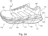
- Fig. 1 shows a sole 101 for a shoe 100, in particular for a sports shoe 100, according to an embodiment of the present disclosure in an exploded view.
- the sole 101 comprises: a midsole 110; and a reinforcing frame 130. At least a first part 136, 137, 138, 139 (as indicated in Figs. 2 to 2C ) of the reinforcing frame 130 substantially surrounds an outer boundary 111 of the midsole 110 in one or more of: a lateral side region 116, a medial side region 115, a heel region 117, and a toe region 118 of the midsole 110 thereby defining an open space 112 (the underlining of reference sign 112 in Fig. 1 indicates that the open space comprises at least the region / space enclosed by the reinforcing frame 130).
- the outer boundary 111 is indicated and described in greater detail with reference to Fig. 4 .
- a part of the midsole 110 is received in the open space 112.
- the first part 136, 137, 138, 139 of the reinforcing frame 130 that substantially surrounds an outer boundary 111 of the midsole 110 may be one or more of the following: a substantially straight lateral segment 136, a curved heel segment 137, a substantially straight medial segment 138, and a curved toe segment 139.
- the reinforcing frame 130 can comprise a second part, such as a substantially straight midfoot segment 140.
- this second part may not surround an outer boundary 111 of the midsole 110 in one or more of: a lateral side region 116, a medial side region 115, a heel region 117 and a toe region 118 of the midsole 110.
- the outer boundary 111 of the midsole 110 faces a lateral side 102 of the sole 101 and / or a medial side 103 of the sole 101.
- the outer boundary 111 may have a normal (such as a normal on a surface) which is at least partially directed to the lateral side 102 of the sole 101 and / or to the medial side 103 of the sole 101.
- the normal of the outer boundary 111 is understood as the line perpendicular to the surface formed by the outer boundary 111.
- the open space 112 is arranged substantially in a plane defined by a heel to toe axis HT and a medial to lateral ML axis of the sole. As understood, since the open space 112 may be three-dimensional, it encompasses more than said plane, however, it may at least extend through said plane as can be seen in Fig. 1 .
- the midsole 110 comprises an upper midsole layer 120 and a lower midsole layer 125, wherein the reinforcing frame 130 is sandwiched between the upper midsole layer 120 and the lower midsole layer 125. From the exemplary embodiment depicted in the exploded view in Fig. 1 , it can be derived that a part of the upper midsole layer 120 is received in the open space 112. However, it is not precluded that further parts of the midsole 110, such as a part of the lower midsole layer 125 are received within the open space 112.
- the upper midsole layer 120 and the lower midsole layer 125 are formed as one unitary piece, such that they are not separated.
- the reinforcing frame 130 may be received at least partially in the midsole 110 by way of grooves, latches, cut-outs, or the like formed in the midsole 110.
- the upper midsole layer 120 and the lower midsole layer 125 are engaged with one another via a form-fit connection, thereby they are defining the outer boundary 111 that is substantially surrounded by the reinforcing frame 130.
- the upper midsole layer 120 may be received at least partially in an opening 126 formed by the lower midsole layer 125, which is, subsequent to receiving, substantially filled with the upper midsole layer 120 (as best seen in Fig. 4 ).
- the reinforcing frame 130 will be placed between the upper midsole layer 120 and the lower midsole layer 125, such that a circumferential surface 129 (also indicated in Fig.
- the lower midsole layer 125 substantially abuts the reinforcing frame 130 and presses it against a circumferential surface 121 (also indicated in Fig. 4 ) of the upper midsole layer 120.
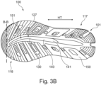
- the circumferential surfaces 129, 121 of the lower midsole layer 125 and of the upper midsole layer 120 are substantially facing each other, having the reinforcing frame 130 placed therebetween. This can also be seen in greater detail with reference to Fig. 3 , Fig. 3A , Fig. 3B , and Fig. 4 .
- the midsole 110 may comprise a polymer foam material.
- the respective advantages in terms of cushioning and energy return of the physical arrangement of the reinforcing frame 130 and the midsole 110, in particular of the upper midsole layer 120 and of the lower midsole layer 125 become even more pronounced due to the good cushioning properties of the foam material.
- the open space 112 is arranged in at least one of: a heel region 112a, a midfoot region 112b, and a toe region 112c of the sole 101.
- the open space may span at least 10%, preferably at least 20%, more preferably at least 30%, more preferably at least 40%, more preferably at least 50%, more preferably at least 60%, more preferably at least 70%, most preferably at least 80% of an underfoot area 104 of the sole 101, and / or at most 99%, preferably at most 95%, most preferably at most 90% of the underfoot area 104 of the sole 101.
- the underfoot area 104 of the sole 101 is exemplarily indicated in Fig. 1 .
- the underfoot area 104 may be defined by the heel region 112a, the midfoot region 112b, and the toe region 112c of the sole 101.
- the underfoot area 104 may be the area with which the bottom of a foot of a wearer would come into contact (disregarding the presence of an upper 160 and / or an insole), when a shoe 100 comprising such a sole 101 is worn by a wearer.
- the reinforcing frame 130 extends from a heel region 112a of the sole 101 to a toe region 112c of the sole 101.
- the frame-like design of the reinforcing frame 130 offers stiffness and stability in portions under the foot where it is most needed, whilst providing a minimalistic design. Thereby also weight-saving advantages can be achieved.
- the reinforcing frame 130 as described herein may serve, for example, to increase the overall stability of the midsole 110, and may provide for a significant increase in energy return to the wearer, without substantially impairing the cushioning and elastic properties of other components of the midsole 110. Hence, the reinforcing frame 110 adds further possibilities to influence the stability properties of the sole 101.
- Fig. 2, Fig. 2A , Fig. 2B, and Fig. 2C show a reinforcing frame 130 for a sole 101 for a shoe 100 according to an embodiment of the present disclosure in four different perspectives.
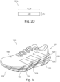
- Fig. 2D shows a schematic cross-sectional cut 131b (as indicated in Fig. 2 ) of a reinforcing arm 131 of a reinforcing frame 130 as used in a sole 101 for a shoe 100 according to an embodiment of the present disclosure.
- the features shown in these figures are applicable to all other embodiments of the sole 101 for a shoe 100 described elsewhere herein. For brevity, not all features of the sole 101 are shown and / or described.
- the reinforcing frame 130 comprises an arm 131, which comprises a flattened profile 132 in a cross-sectional cut 131b perpendicular to a longitudinal axis 131a of the arm 131.
- the flattened profile 132 has a width w_fp (as best seen in Fig.
- the flattened profile 132 has a thickness t_fp substantially perpendicular to a plane defined by a heel to toe axis HT and a medial to lateral axis ML of the sole 101, of at least 0.2 mm, preferably at least 0.5 mm, more preferably at least 0.8 mm, even more preferably at least 1.0 mm, further more preferably at least 1.2 mm, most preferably at least 1.5 mm, and /or of at most 3 mm, preferably at most 2.5 mm, more preferably at most 2.0 mm, even more preferably at most 1.8 mm, most preferably at most 1.5 mm.
- the reinforcing frame 130 may have a substantially a uniform thickness.
- the reinforcing frame 130 may be provided with structures, such as raised structures and / or embossed structures. These structures may have any shape and may serve the purpose of reinforcing some portions of the reinforcing frame 130. In one example, these structures may be provided in substantially regular patterns along the length of the arm 131. For instance, it can be seen from Fig. 2A , that such structures are provided at least along a lateral segment 136 (as described further below), along a heel segment 137, and / or along a medial segment 138 of the arm 131 of the reinforcing frame 130.
- the reinforcing frame 130 is formed so as to define a three-dimensional shape, such that it is arranged in at least two substantially parallel planes 142, 143 defined by the heel to toe axis HT and the medial to lateral axis ML of the sole 101, the two planes 142, 143 being spaced apart (indicated by the term s) by at least 1 cm, preferably at least 1.5 cm, more preferably at least 2 cm, even more preferably at least 2.5 cm, even more preferably at least 3 cm, further more preferably at least 3.5 cm, most preferably by at least 3.6 cm, and / or by at most 5 cm, preferably at most 4.5 cm, more preferably at most 4.2 cm, most preferably by at most 4.0 cm.
- the two substantially parallel planes 142, 143 are indicated in Fig. 2C by way of the dashed lines and are understood to project into infinite space in a horizontal direction.
- a heel segment 137 of the reinforcing frame 130 extends by a greater amount in an upward direction UD compared to any other segment 136, 138, 139, 140 of the reinforcing frame 130.
- the reinforcing frame 130 comprises an open frame structure having a first end 135 and a second end 141, wherein the first end 135 and the second end 141 are spaced apart from each other.
- the first end 135 and the second end 141 may be spaced apart from each other by at least 10%, preferably at least 20%, more preferably at least 30%, even more preferably at least 40%, most preferably at least 50% of the length of the sole 101 (as best seen in Fig. 1 ), and / or of at most 80%, preferably at most 70%, more preferably at most 60%, most preferably at most 50% of the length of the sole 101. It is understood that the length of the sole 101 may be measured along the heel-to-toe axis HT of the sole 101.
- the first end 135 may be arranged in a toe region 112c of the sole 101, preferably in a little toe region of the sole 101.
- the second end 141 may be arranged in a midfoot region 112b of the sole 101.
- the reinforcing frame 130 may have the following segments 136, 138, 139, 140 in the following order from the first end 135 to the second end 141: a substantially straight lateral segment 136, a curved heel segment 137, a substantially straight medial segment 138, a curved toe segment 139, and a substantially straight midfoot segment 140.
- midfoot region 112b of the sole 101 and / or the toe region 112c of the sole 101 portion may be subject to a range of movements and / or pressures during athletic activities. Therefore, improvements to these regions 112b, 112c contribute to a more comfortable and enhanced sole 101.
- the reinforcing frame 130 comprises a midfoot segment 140
- the reinforcing frame 130 can nonetheless define an open space 112 in the midfoot region 112b of the sole 101. This may be particularly derivable from Fig. 2B and Fig. 2C .
- a width w_se of the midfoot segment 140 is greater than any other width (the width w_ts of the toe segment 139 and the width w_ls of the lateral segment 138 are exemplarily indicated in Fig. 2A ) of the reinforcing frame 130, the width w_se being substantially along a plane defined by a heel to toe axis HT and a medial to lateral axis ML of the sole 101.
- the width w_se of the reinforcing frame 130 decreases from the second end 141 along the midfoot segment 140 towards the toe segment 139, the width w_se being substantially in a plane defined by a heel to toe axis and a medial to lateral axis of the sole.
- the midfoot segment 140 in particular the second end 141, extends by a greater amount in a downward direction DD compared to any other segment 136, 138, 139, 140 of the reinforcing frame 130.
- the three-dimensional shape may be understood such that the reinforcing frame 130 may be formed so as to define a helical shape.
- a helical shape may be a shape that resembles a helix or spiral.
- a helix is a curve that winds around a central axis.
- a helix may wind around a central axis in a consistent manner, creating a spiral-like pattern.
- a distance to the central axis may vary, which may be a preferred shape so as to adapt to the shape of the midsole 110.
- the reinforcing frame 130 as shown in Fig. 2, Fig. 2A , Fig. 2B, and Fig. 2C may be understood to be constructed so as to form a sling shot, starting substantially under the little toe of a wearer, wrapping around the heel of the wearer, running underneath the big toe of the wearer and back underneath the midfoot of the wearer.
- This construction facilitates stiffening of the midfoot portion to forefoot portion resulting in an enhanced energy return whilst also stabilizing the landing phase of the wearer and supporting the wearer. This may be helpful when the gait cycle of the wearer is not ideal and / or varies depending on the fatigue of the wearer.
- an exemplary dashed box 130a and an exemplary dashed box 130b are indicated, which can represent a first portion 130a of the reinforcing frame 130 and a second portion 130b of the reinforcing frame 130.
- the first portion 130a of the reinforcing frame 130 may be covered and / or embedded in the midsole 110 when the sole 101 is in an assembled condition (as can be derived from the exploded view in Fig. 1 ). It is noted that this first portion 130a may be different than the second part of the reinforcing frame 130, such as the substantially straight midfoot segment 140 (which may not surround the outer boundary 111 of the midsole 110). This means that the first portion 130a of the reinforcing frame 130 is considered to surround the outer boundary 111 of the midsole 110 as described elsewhere herein in greater detail.
- the second portion 130b of the reinforcing frame 130 may be exposed to the exterior when the sole 101 is in an assembled condition (as can be derived from the exploded view in Fig. 1 ).
- the size of the first portion 130a and /or of the second portion 130b can vary as understood by the skilled person.
- the first portion 130a and /or of the second portion 130b may extend along one or more of: the substantially straight lateral segment 136, the curved heel segment 137, the substantially straight medial segment 138, and the curved toe segment 139. Further, also their width may vary depending on the specific arrangement of the sole 101, as understood by the skilled person.
- the size of the first portion 130a and /or of the second portion 130b is indicated merely by way of example in Fig. 2 .
- Fig. 3 , Fig. 3A , and Fig. 3B show a shoe 100, in particular a sports shoe 100, comprising an upper 160 according to an embodiment of the present disclosure in three different perspectives.
- the features shown in these figures are applicable to all other embodiments of the sole 101 for a shoe 100 described elsewhere herein. For brevity, not all features of the sole 101 are shown and / or described.
- the sole 101 comprises an outsole 150 arranged below the lower midsole layer 125.
- the outsole 150 has a cut-out 151 (as best seen in Fig. 3B ), arranged such that the reinforcing frame 130 is at least partially visible from below the outsole 150.
- the cut-out 151 may have an elongated shape aligned along the heel to toe axis HT of the sole 101.
- the cut-out 151 is arranged such that the midfoot segment 140 of the reinforcing frame 130 is at least partially visible from below the outsole 150.
- the lower midsole layer 125 has a cut-out 127, arranged such that the reinforcing frame 130 is at least partially visible from below the outsole 150.
- This cut-out 127 may have an elongated shape aligned along the heel to toe axis HT of the sole 101.
- the cut-out 127 of the lower midsole layer 125 may be arranged such that the midfoot segment 140 of the reinforcing frame 130 is at least partially visible from below the outsole 101.
- the cut-out 127 of the lower midsole layer 125 may be shaped substantially in correspondence with the cut-out 151 of the outsole 150.
- Such cut-outs 151, 127 have, on the one side, the advantage that less material is required for manufacturing.
- the cut-outs 151, 127 may allow for breathability, e.g., they may allow for air circulation and moisture wicking which can reduce overheating and sweat accumulation.
- the cut-outs 151, 127 may have the further advantages that due to a reduction of moisture, the longevity of the shoe may be enhanced.
- the cut-outs 151, 127 may have the further advantage of reducing the weight of the midsole, thereby reducing the overall weight of the sole 101 and the shoe 100.
- a lightweight shoe 101 is particularly advantageous when it is used for an athletic activity like running.
- One or both of the cut-outs 151, 127 may have a length in a longitudinal direction of the outsole 150 and / or of the midsole 110, such as along the heel to toe axis HT, of at least 2 cm, preferably at least 4 cm, more preferably at least 6 cm, even more preferably at least 8 cm, further more preferably at least 10 cm, further more preferably at least 12 cm, further more preferably at least 15 cm, further more preferably at least 20 cm, further more preferably at least 25 cm, and most preferably of at least 30 cm.
- One or both of the cut-outs 151, 127 may have a tapered shape along the heel to toe axis HT.
- the reinforcing frame 130 is at least partially visible from outside the shoe 100.
- the reinforcing frame 130 is preferably visible from a medial side 103, a heel side and / or a lateral side 102 of the sole 101.
- one or more recesses 128 may be provided in the lateral side region 116 of the midsole 110 and / or the medial side region 115 of the midsole 110 or, in other words, in the sidewalls of the midsole 110.
- Fig. 3A four recesses 128 are indicated.
- the one or more recesses 128 may have an elongated shape.
- the one or more recesses 128 are angled with respect to an upward direction UD and downward direction DD, wherein the angle increases from a recess 128 arranged in a front portion to a recess 128 in a rear portion of the midsole 110. The increase of the angle may be substantially continuous.
- the one or more recesses 128 may be substantially continuously formed across the upper midsole layer 120 and the lower midsole layer 125 as depicted in Fig. 3A . Further, as the one or more recesses 128 provide for a space in the material of the midsole 110, the reinforcing frame 130 is visible to a greater extent in these recesses 128.
- the one or more recesses 128 may have the advantage that the reinforcing frame 130 does not completely abut a lower circumferential surface 121 of the upper midsole layer 120 and / or an upper circumferential surface 129 of the lower midsole layer 125. This may allow for some variations and fine-tuning in terms of energy return to the wearer.
- the one or more recesses 128 may not be through holes.
- the one or more recesses 128 may have the shape of one of a slit, a groove, a cut, or a vent. These shapes may have the potential to impart certain functional properties to the midsole 110. For instance, a distribution of the pressure load may be influenced thereby to a greater extent. This may be appreciated by an athlete performing his or her athletic activity.
- the shapes may be described as follows and have the following advantages:
- a slit may be a rather long, narrow opening and / or a cut in a material, such as a material of the midsole 110.
- a slit typically has a length that is greater than its width, in some instances its length is significantly greater than is width.
- its length may be greater than its width by a factor of at least two, at least three, at least four, at least five, at least six, at least seven, at least eight, at least nine, at least ten or even greater.
- Slits can be straight or curved and they can be composed of one or more straight segments and one or more curved segments. Further, the one or more recesses 128 being shaped like slits may, together with one or more remaining parts of the sole 101 be designed to collapse and / or to facilitate a guided deformation of the sole 101.
- a groove may be a long, narrow channel and / or recessed portion, which may be cut into a material, such as a material of the midsole 110.
- the grooves may be useful for various purposes, such as guiding the flow of liquids, or the like. This may aid in removing moisture resulting from sweat or the like. In turn this can also improve odor.
- the grooves can be shallow and / or deep. As understood by the skilled person, this may depend on the thickness of the midsole 110.
- the grooves may be wide or narrow.
- the grooves may appear in a variety of shapes, including one or more of straight segments, curved segments, corner segments, regular segments, or irregular segments.
- a cut may refer to a separation or division made in a material, such as a material of the midsole 110.
- a cut may be provided by applying a sharp edge or tool into the material. Cuts may be straight or angled and can be used for a wide range of purposes, including creating openings, shaping materials, or altering the structure of an object, such as the midsole 110. The cuts may appear in a variety of shapes, including one or more of straight segments, curved segments, corner segments, regular segments, or irregular segments.
- a vent is an opening or passage in a material, such as a material of the midsole 110.
- a vent may allow for movement of gases, such as air, or liquids therethrough. Vents may be useful in regulating a temperature of the foot of the wearer.
- the vents may be implemented by various different shapes and / or size sizes, including one or more of straight segments, curved segments, corner segments, regular segments, or irregular segments.
- the upper 160 may be attached to the sole 101 by any kind of suitable means of attachment.
- attaching may include cementing / adhesive bonding, which is a common method, in which for instance a strong adhesive is applied to one or both of the upper 160 and the sole 101. Subsequently, they may be pressed together and allowed to bond. This method may be employed for sports shoes, casual shoes, or the like.
- attaching may include stitching the upper 160 to the sole 101. Such a method may involve sewing the upper 160 and the sole 101 together. The stitching may be fully or at least partially visible or fully or at least partially hidden within the sole 101. Further, attaching may include injection molding.
- attaching may include the application of soling sheets, which comprise soling material (such as rubber and / or EVA), which are cut to shape and then attached to the sole 101 and upper 160 using adhesive and / or heat bonding.
- soling sheets which comprise soling material (such as rubber and / or EVA)
- attaching may include strobel stitching, which may often be performed in athletic shoes and / or casual shoes.
- the upper 160 is stitched to an insole 101 before being attached to the sole 101 using adhesive or cementing.
- attaching may include crimping, in which crimps comprising metal and / or plastic are used to join the upper 160 and sole 101 together.
- attaching may include lasting.
- Such a lasting method may involve pulling the upper 160 over a last (i.e., a shoe-shaped form) and securing it to the sole 101 by tacking, stitching, and / or cementing. Further, attaching may include vulcanization.
- rubber soles 101 may be employed, which are cured in order to bond it with the upper 160. It is often employed in some types of athletic shoes.
- the upper 160 may be attached to the sole 101 by means of fusion bonding, thermal bonding, ultrasonic bonding, or the like.
- Fig. 3C shows a shoe 100, in particular a sports shoe 100, comprising an upper 160 according to an embodiment of the present disclosure in a perspective view from the bottom.
- the features shown in these figures are applicable to all other embodiments of the sole 101 for a shoe 100 described elsewhere herein.
- the lower midsole layer 125 has a cut-out 127, arranged such that the reinforcing frame 130 is at least partially visible from below the outsole 150. This cut-out 127 has a different shape as compared to Fig. 3B .
- the cut-out 127 extends from a heel region 117 of the lower midsole layer 125 towards a midfoot portion of the lower midsole layer 125.
- the cut-out 127 of the lower midsole layer 125 may be shaped substantially in correspondence with the cut-out 151 of the outsole 150. Similar advantages of the cut-outs 151, 127 as explained with respect to Fig. 3B apply to this embodiment as well. It may be possible that the configuration of the cut-outs 127, 151 of the embodiment depicted in Fig. 3C is preferred as compared to the embodiment depicted in Fig. 3B .
- Fig. 4 shows a schematic cross-sectional view of a midsole sole 110 as used in a sole 101 for a shoe 100 according to an embodiment of the present disclosure.
- the schematic cross-sectional view of this figures is indicated via the cross-sectional cut B - B in Fig. 3B and Fig. 3C .
- the features shown in this figure are applicable to all other embodiments of the sole 101 for a shoe 100 described elsewhere herein. For brevity, not all features of the sole 101 are shown and / or described.
- the outer boundary 111 of the midsole 110 may be a surface of the midsole 110, the normal of which being substantially perpendicularly to the upward direction UD and downward direction DD.
- the outer boundary 111 of the midsole 110 may define the outer shape of the midsole 110 at least partially.
- the outer boundary 111 of the midsole 110 may be referred to as the part that is visible when the midsole 110 is viewed from the outside, e.g., from a side of the sole 101, such as a medial side and / or a lateral side.
- the reinforcing frame 130 substantially surrounds the outer boundary 111 of the midsole 110, the outer boundary 111 may not be fully visible from outside the shoe 100.
- Fig. 4 indicates the open space 112, which is defined by the reinforcing frame 130 and which is free from the reinforcing frame 130. Since Fig. 4 is a cross-sectional cut in a midfoot region 112b of the sole 101, the midfoot region 112b, which is encompassed by the open space 112, is also depicted. A part of the midsole 110 is received in the open space 112. In the example of Fig. 4 , it is indicated that a part of the upper midsole layer 120 is received in the open space 112. In order words, the upper midsole layer 120 fills out at least partially the open space 112 so as to engage with the lower midsole layer 125.
- the reinforcing frame 130 in the cross-sectional cut has a midfoot segment 140, which is spaced further in the downward direction DD as compared to the medial segment 138 and / or lateral segment 136.
- the upper midsole layer 120 comprises a first material and the lower midsole layer 125 comprises a second material, wherein the first material preferably has a lower stiffness compared to the second material.
- the reinforcing frame 130 comprises or consists of one or more of the following materials: thermoplastic polyurethane, TPU, polyamide, in particular nylon polyamide, carbon fibers, a carbon fiber composite material, a glass fiber composite material.
- the midsole 110 comprises or consists of a particle foam material, in particular a particle foam material comprising one or more of the following materials: expanded thermoplastic polyurethane (eTPU); expanded polyamide (ePA); expanded polyether-block-amide (ePEBA); expanded polylactide (ePLA); expanded polyethylene terephthalate (ePET); ex-panded polybutylene terephthalate (ePBT); expanded thermoplastic polyester ether elastomer (eTPEE).
- eTPU expanded thermoplastic polyurethane
- ePA expanded polyamide
- ePEBA expanded polyether-block-amide
- ePLA expanded polylactide
- ePET expanded polyethylene terephthalate
- ePBT ex-panded polybutylene terephthalate
- eTPEE expanded thermoplastic polyester ether elastomer
- the foam particles used for the midsole 110 may be made of, or comprise, expanded thermo-plastic materials, especially thermoplastic polyurethane (TPU), polylactate (PLA), polyamide (PA), polyether block amide (PEBA), polyethylene terephthalate (PET), polybutylene terephthalate (PBT), or thermoplastic polyester ether elastomer (TPEE).
- TPU thermoplastic polyurethane
- PLA polylactate
- PA polyamide
- PEBA polyether block amide
- PET polyethylene terephthalate
- PBT polybutylene terephthalate
- TPEE thermoplastic polyester ether elastomer
- the foam particles used for the midsole 110 may also be a bead containing multiple polymer types in one foam particle or the foam particles may be a mixture of different particles of different foam polymers or combinations thereof.
- the foam particles used for the midsole 110 consist of 90 % by weight of one or a mixture of these materials. The particles are described elsewhere herein in greater detail.
- the midsole 110 comprises or consists of a foam material manufactured in one foaming step.
- foams are often referred to as “homogeneous foams", “block foams” or “integral foams”.
- these foams that can be used as a material for the midsole 110 in any one of the embodiments of the sole 101 for a shoe 100 as described herein are produced in one foaming step using blowing agents and these foams do not have a recognizable granular structure, i.e., they do not have any identifiable particles within the finished foam and only a singular internal cellular structure, unlike bead foams which contain multiple beads each containing an internal cellular structure and with intersections between the individual expanded beads which create a granular structure.
- Homogenous foams or block foams can be made from well-known state of the art polymers such as ethylene-vinyl acetate (EVA), thermoplastic polyester ether elastomer (TPEE), polyether-block-amide (PEBA), polyurethane (PU) etc.
- EVA ethylene-vinyl acetate
- TPEE thermoplastic polyester ether elastomer
- PEBA polyether-block-amide
- PU polyurethane
- Particle foam material or particle foam on the other hand is different compared to homogeneous foam.
- expanded particles or beads are created in a first step from a particulate base material that is foamed. These expanded beads can then be assembled in a second step to form a coherent structure in which the individual particle boundaries are discernible, i.e., clearly visible, in the finished foam. Expanded in this context means that each individual particle has a core of foamed material with many small foam cells, i.e., the particle may not consist of a compact, solid material.
Landscapes
- Chemical & Material Sciences (AREA)
- Engineering & Computer Science (AREA)
- Materials Engineering (AREA)
- Health & Medical Sciences (AREA)
- General Health & Medical Sciences (AREA)
- Physical Education & Sports Medicine (AREA)
- Epidemiology (AREA)
- Public Health (AREA)
- Footwear And Its Accessory, Manufacturing Method And Apparatuses (AREA)
Applications Claiming Priority (1)
| Application Number | Priority Date | Filing Date | Title |
|---|---|---|---|
| DE102023210927.1A DE102023210927A1 (de) | 2023-11-03 | 2023-11-03 | Sohle, umfassend einen Verstärkungsrahmen |
Publications (1)
| Publication Number | Publication Date |
|---|---|
| EP4548794A1 true EP4548794A1 (fr) | 2025-05-07 |
Family
ID=93154318
Family Applications (1)
| Application Number | Title | Priority Date | Filing Date |
|---|---|---|---|
| EP24207165.2A Pending EP4548794A1 (fr) | 2023-11-03 | 2024-10-17 | Semelle comprenant un cadre de renfort |
Country Status (5)
| Country | Link |
|---|---|
| US (1) | US20250143406A1 (fr) |
| EP (1) | EP4548794A1 (fr) |
| JP (1) | JP2025078027A (fr) |
| CN (1) | CN119924612A (fr) |
| DE (1) | DE102023210927A1 (fr) |
Citations (12)
| Publication number | Priority date | Publication date | Assignee | Title |
|---|---|---|---|---|
| EP1002473B1 (fr) | 1998-11-17 | 2003-07-30 | Lotto Sport Italia S.p.A. | Dispositif pour augmenter la stabilité de mouvement pour des chaussures de tennis ou autres |
| US20040154188A1 (en) * | 2003-02-07 | 2004-08-12 | Columbia Sportswear North America, Inc. | Footwear with dual-density midsole and deceleration zones |
| US7263788B2 (en) | 2002-03-06 | 2007-09-04 | Nike, Inc. | Sole-mounted footwear stability system |
| EP2649896A2 (fr) | 2012-04-13 | 2013-10-16 | Adidas AG | Semelles pour chaussures de sport |
| US8984775B2 (en) | 2012-02-24 | 2015-03-24 | Under Armour, Inc. | Energy return member for footwear |
| WO2016030026A1 (fr) | 2014-08-26 | 2016-03-03 | Adidas Ag | Pastilles polymères expansées |
| US20180116335A1 (en) * | 2015-05-04 | 2018-05-03 | Nike, Inc. | Footwear Sole Structure Including a Spring Plate |
| KR102097381B1 (ko) | 2019-11-18 | 2020-04-06 | (주) 에프앤에이글로벌 | 충격흡수 및 보행추진 기능을 갖는 밑창 및 이를 포함하는 신발 |
| US10842224B2 (en) | 2015-10-02 | 2020-11-24 | Nike, Inc. | Plate for footwear |
| US20210093039A1 (en) * | 2019-09-27 | 2021-04-01 | Adidas Ag | Sole element |
| EP3868242A2 (fr) | 2020-02-21 | 2021-08-25 | adidas AG | Semelle comprenant des éléments de renfort individuellement orientables et chaussure comprenant une telle semelle |
| WO2021260920A1 (fr) * | 2020-06-26 | 2021-12-30 | 株式会社アシックス | Semelle de chaussure et chaussure |
Family Cites Families (21)
| Publication number | Priority date | Publication date | Assignee | Title |
|---|---|---|---|---|
| US5937544A (en) * | 1997-07-30 | 1999-08-17 | Britek Footwear Development, Llc | Athletic footwear sole construction enabling enhanced energy storage, retrieval and guidance |
| FR2794005B1 (fr) * | 1999-05-26 | 2001-06-29 | Imp Ation De Diffusion Ou Dist | Semelle de chaussure |
| JP3947658B2 (ja) * | 2001-06-28 | 2007-07-25 | 美津濃株式会社 | スポーツ用シューズのミッドソール構造 |
| US6775930B2 (en) * | 2003-01-28 | 2004-08-17 | Rofu Design | Key hole midsole |
| JP4704429B2 (ja) * | 2005-05-13 | 2011-06-15 | 株式会社アシックス | 靴底の緩衝装置 |
| EP1898738A4 (fr) * | 2005-07-01 | 2014-05-14 | Karhu Holding B V | Structure de semelle d'une chaussure de sport |
| US20100307028A1 (en) * | 2008-12-16 | 2010-12-09 | Skechers U.S.A. Inc. Ii | Shoe |
| US8479413B2 (en) * | 2008-12-22 | 2013-07-09 | Msd Consumer Care, Inc. | Footwear insole for alleviating arthritis pain |
| US8356428B2 (en) * | 2009-10-20 | 2013-01-22 | Nike, Inc. | Article of footwear with flexible reinforcing plate |
| US9167867B2 (en) * | 2010-05-13 | 2015-10-27 | Nike, Inc. | Article of footwear with multi-part sole assembly |
| EP2685858A4 (fr) * | 2011-03-18 | 2014-08-20 | Columbia Sportswear Na Inc | Semelle intercalaire à haute stabilité et densité multiple |
| US9615625B1 (en) * | 2015-09-17 | 2017-04-11 | Wolverine Outdoors, Inc. | Sole assembly for article of footwear |
| US10524540B1 (en) * | 2018-07-17 | 2020-01-07 | Nike, Inc. | Airbag for article of footwear |
| JP6913432B2 (ja) * | 2019-03-31 | 2021-08-04 | 美津濃株式会社 | シューズのソール構造体 |
| US11439199B2 (en) * | 2019-10-18 | 2022-09-13 | Wolverine Outdoors, Inc. | Footwear sole assembly |
| US11737513B2 (en) * | 2019-12-25 | 2023-08-29 | Asics Corporation | Shoe and method for manufacturing shoe |
| WO2022043945A1 (fr) * | 2020-08-31 | 2022-03-03 | Puma SE | Articles chaussants en bois modifié |
| US12064003B2 (en) * | 2020-10-28 | 2024-08-20 | Puma SE | Articles of footwear with support structures |
| JP2022079271A (ja) * | 2020-11-16 | 2022-05-26 | 株式会社アシックス | 靴底および靴 |
| CN118235912A (zh) * | 2022-12-23 | 2024-06-25 | 索克尼公司 | 具有鞋底板的鞋类制品 |
| JP2024151558A (ja) * | 2023-04-12 | 2024-10-25 | 株式会社アシックス | ソールおよびこれを備えた靴 |
-
2023
- 2023-11-03 DE DE102023210927.1A patent/DE102023210927A1/de active Pending
-
2024
- 2024-10-17 EP EP24207165.2A patent/EP4548794A1/fr active Pending
- 2024-10-25 US US18/926,971 patent/US20250143406A1/en active Pending
- 2024-10-28 JP JP2024188725A patent/JP2025078027A/ja active Pending
- 2024-11-01 CN CN202411549410.1A patent/CN119924612A/zh active Pending
Patent Citations (13)
| Publication number | Priority date | Publication date | Assignee | Title |
|---|---|---|---|---|
| EP1002473B1 (fr) | 1998-11-17 | 2003-07-30 | Lotto Sport Italia S.p.A. | Dispositif pour augmenter la stabilité de mouvement pour des chaussures de tennis ou autres |
| US7263788B2 (en) | 2002-03-06 | 2007-09-04 | Nike, Inc. | Sole-mounted footwear stability system |
| US20040154188A1 (en) * | 2003-02-07 | 2004-08-12 | Columbia Sportswear North America, Inc. | Footwear with dual-density midsole and deceleration zones |
| US8984775B2 (en) | 2012-02-24 | 2015-03-24 | Under Armour, Inc. | Energy return member for footwear |
| EP2649896A2 (fr) | 2012-04-13 | 2013-10-16 | Adidas AG | Semelles pour chaussures de sport |
| WO2016030333A1 (fr) | 2014-08-26 | 2016-03-03 | Adidas Ag | Pastilles en polyamide expansé et procédé de fabrication d'éléments moulés dans lequel on les utilise |
| WO2016030026A1 (fr) | 2014-08-26 | 2016-03-03 | Adidas Ag | Pastilles polymères expansées |
| US20180116335A1 (en) * | 2015-05-04 | 2018-05-03 | Nike, Inc. | Footwear Sole Structure Including a Spring Plate |
| US10842224B2 (en) | 2015-10-02 | 2020-11-24 | Nike, Inc. | Plate for footwear |
| US20210093039A1 (en) * | 2019-09-27 | 2021-04-01 | Adidas Ag | Sole element |
| KR102097381B1 (ko) | 2019-11-18 | 2020-04-06 | (주) 에프앤에이글로벌 | 충격흡수 및 보행추진 기능을 갖는 밑창 및 이를 포함하는 신발 |
| EP3868242A2 (fr) | 2020-02-21 | 2021-08-25 | adidas AG | Semelle comprenant des éléments de renfort individuellement orientables et chaussure comprenant une telle semelle |
| WO2021260920A1 (fr) * | 2020-06-26 | 2021-12-30 | 株式会社アシックス | Semelle de chaussure et chaussure |
Also Published As
| Publication number | Publication date |
|---|---|
| DE102023210927A1 (de) | 2025-05-08 |
| US20250143406A1 (en) | 2025-05-08 |
| CN119924612A (zh) | 2025-05-06 |
| JP2025078027A (ja) | 2025-05-19 |
Similar Documents
| Publication | Publication Date | Title |
|---|---|---|
| US11918078B2 (en) | Foot support members that provide dynamically transformative properties | |
| US7487604B2 (en) | Soccer shoe component or insert made of one material and/or a composite and/or laminate of one or more materials for enhancing the performance of the soccer shoe | |
| US20200068987A1 (en) | Soccer Shoe Component or Insert Made of One Material and/or a Composite and/or Laminate of One or More Materials for Enhancing the Performance of the Soccer Shoe | |
| CN111011987B (zh) | 用于鞋的鞋底 | |
| US8181365B2 (en) | Article of footwear including improved heel structure | |
| JP5444528B2 (ja) | 歩行具 | |
| EP2684479A2 (fr) | Chaussures avec projections de semelle | |
| AU2010201593A1 (en) | Shoe assembly with non-linear viscous liquid | |
| CN115251529B (zh) | 鞋底元件 | |
| US12364308B2 (en) | Golf shoe with reinforcement structure | |
| EP4570109A1 (fr) | Plaque de semelle pour un article chaussant | |
| US20140230283A1 (en) | Athletes footwear | |
| EP4548794A1 (fr) | Semelle comprenant un cadre de renfort | |
| CN120859245A (zh) | 跑鞋的鞋底 | |
| EP4541212B1 (fr) | Semelle intercalaire avec une structure de cisaillement pour chaussure et son procédé de fabrication | |
| EP4537695A1 (fr) | Article chaussant avec un ou plusieurs crampons | |
| US20050160630A1 (en) | Soccer shoe component or insert made of one material and/or a composite and/or laminate of one or more materials for enhancing the performance of the soccer shoe | |
| US20220000210A1 (en) | Sole of a shoe having a preferred flexing zone, and shoe having such an outer sole | |
| WO2005096733A2 (fr) | Composant ou insert de chaussure de foot fait d'un materiau et/ou d'un materiau composite et/ou lamine fait d'un ou de plusieurs materiaux destines a ameliorer l'efficacite de la chaussure de foot | |
| Easterling | Sports shoes | |
| ITFI20100010A1 (it) | Calzatura sportiva |
Legal Events
| Date | Code | Title | Description |
|---|---|---|---|
| PUAI | Public reference made under article 153(3) epc to a published international application that has entered the european phase |
Free format text: ORIGINAL CODE: 0009012 |
|
| STAA | Information on the status of an ep patent application or granted ep patent |
Free format text: STATUS: REQUEST FOR EXAMINATION WAS MADE |
|
| 17P | Request for examination filed |
Effective date: 20241017 |
|
| AK | Designated contracting states |
Kind code of ref document: A1 Designated state(s): AL AT BE BG CH CY CZ DE DK EE ES FI FR GB GR HR HU IE IS IT LI LT LU LV MC ME MK MT NL NO PL PT RO RS SE SI SK SM TR |