EP4548826A1 - Appareil de nettoyage - Google Patents
Appareil de nettoyage Download PDFInfo
- Publication number
- EP4548826A1 EP4548826A1 EP23891919.5A EP23891919A EP4548826A1 EP 4548826 A1 EP4548826 A1 EP 4548826A1 EP 23891919 A EP23891919 A EP 23891919A EP 4548826 A1 EP4548826 A1 EP 4548826A1
- Authority
- EP
- European Patent Office
- Prior art keywords
- unit
- suction
- cleaning device
- roller
- suction unit
- Prior art date
- Legal status (The legal status is an assumption and is not a legal conclusion. Google has not performed a legal analysis and makes no representation as to the accuracy of the status listed.)
- Pending
Links
Images





Classifications
-
- A—HUMAN NECESSITIES
- A47—FURNITURE; DOMESTIC ARTICLES OR APPLIANCES; COFFEE MILLS; SPICE MILLS; SUCTION CLEANERS IN GENERAL
- A47L—DOMESTIC WASHING OR CLEANING; SUCTION CLEANERS IN GENERAL
- A47L9/00—Details or accessories of suction cleaners, e.g. mechanical means for controlling the suction or for effecting pulsating action; Storing devices specially adapted to suction cleaners or parts thereof; Carrying-vehicles specially adapted for suction cleaners
- A47L9/02—Nozzles
- A47L9/04—Nozzles with driven brushes or agitators
- A47L9/0461—Dust-loosening tools, e.g. agitators, brushes
- A47L9/0466—Rotating tools
-
- A—HUMAN NECESSITIES
- A47—FURNITURE; DOMESTIC ARTICLES OR APPLIANCES; COFFEE MILLS; SPICE MILLS; SUCTION CLEANERS IN GENERAL
- A47L—DOMESTIC WASHING OR CLEANING; SUCTION CLEANERS IN GENERAL
- A47L9/00—Details or accessories of suction cleaners, e.g. mechanical means for controlling the suction or for effecting pulsating action; Storing devices specially adapted to suction cleaners or parts thereof; Carrying-vehicles specially adapted for suction cleaners
- A47L9/02—Nozzles
- A47L9/04—Nozzles with driven brushes or agitators
- A47L9/0461—Dust-loosening tools, e.g. agitators, brushes
- A47L9/0466—Rotating tools
- A47L9/0477—Rolls
-
- A—HUMAN NECESSITIES
- A47—FURNITURE; DOMESTIC ARTICLES OR APPLIANCES; COFFEE MILLS; SPICE MILLS; SUCTION CLEANERS IN GENERAL
- A47L—DOMESTIC WASHING OR CLEANING; SUCTION CLEANERS IN GENERAL
- A47L7/00—Suction cleaners adapted for additional purposes; Tables with suction openings for cleaning purposes; Containers for cleaning articles by suction; Suction cleaners adapted to cleaning of brushes; Suction cleaners adapted to taking-up liquids
- A47L7/02—Suction cleaners adapted for additional purposes; Tables with suction openings for cleaning purposes; Containers for cleaning articles by suction; Suction cleaners adapted to cleaning of brushes; Suction cleaners adapted to taking-up liquids with driven tools for special purposes
-
- A—HUMAN NECESSITIES
- A47—FURNITURE; DOMESTIC ARTICLES OR APPLIANCES; COFFEE MILLS; SPICE MILLS; SUCTION CLEANERS IN GENERAL
- A47L—DOMESTIC WASHING OR CLEANING; SUCTION CLEANERS IN GENERAL
- A47L9/00—Details or accessories of suction cleaners, e.g. mechanical means for controlling the suction or for effecting pulsating action; Storing devices specially adapted to suction cleaners or parts thereof; Carrying-vehicles specially adapted for suction cleaners
- A47L9/02—Nozzles
- A47L9/04—Nozzles with driven brushes or agitators
-
- A—HUMAN NECESSITIES
- A47—FURNITURE; DOMESTIC ARTICLES OR APPLIANCES; COFFEE MILLS; SPICE MILLS; SUCTION CLEANERS IN GENERAL
- A47L—DOMESTIC WASHING OR CLEANING; SUCTION CLEANERS IN GENERAL
- A47L9/00—Details or accessories of suction cleaners, e.g. mechanical means for controlling the suction or for effecting pulsating action; Storing devices specially adapted to suction cleaners or parts thereof; Carrying-vehicles specially adapted for suction cleaners
- A47L9/02—Nozzles
- A47L9/04—Nozzles with driven brushes or agitators
- A47L9/0405—Driving means for the brushes or agitators
-
- A—HUMAN NECESSITIES
- A47—FURNITURE; DOMESTIC ARTICLES OR APPLIANCES; COFFEE MILLS; SPICE MILLS; SUCTION CLEANERS IN GENERAL
- A47L—DOMESTIC WASHING OR CLEANING; SUCTION CLEANERS IN GENERAL
- A47L9/00—Details or accessories of suction cleaners, e.g. mechanical means for controlling the suction or for effecting pulsating action; Storing devices specially adapted to suction cleaners or parts thereof; Carrying-vehicles specially adapted for suction cleaners
- A47L9/28—Installation of the electric equipment, e.g. adaptation or attachment to the suction cleaner; Controlling suction cleaners by electric means
-
- A—HUMAN NECESSITIES
- A47—FURNITURE; DOMESTIC ARTICLES OR APPLIANCES; COFFEE MILLS; SPICE MILLS; SUCTION CLEANERS IN GENERAL
- A47L—DOMESTIC WASHING OR CLEANING; SUCTION CLEANERS IN GENERAL
- A47L9/00—Details or accessories of suction cleaners, e.g. mechanical means for controlling the suction or for effecting pulsating action; Storing devices specially adapted to suction cleaners or parts thereof; Carrying-vehicles specially adapted for suction cleaners
- A47L9/28—Installation of the electric equipment, e.g. adaptation or attachment to the suction cleaner; Controlling suction cleaners by electric means
- A47L9/2805—Parameters or conditions being sensed
-
- A—HUMAN NECESSITIES
- A47—FURNITURE; DOMESTIC ARTICLES OR APPLIANCES; COFFEE MILLS; SPICE MILLS; SUCTION CLEANERS IN GENERAL
- A47L—DOMESTIC WASHING OR CLEANING; SUCTION CLEANERS IN GENERAL
- A47L9/00—Details or accessories of suction cleaners, e.g. mechanical means for controlling the suction or for effecting pulsating action; Storing devices specially adapted to suction cleaners or parts thereof; Carrying-vehicles specially adapted for suction cleaners
- A47L9/28—Installation of the electric equipment, e.g. adaptation or attachment to the suction cleaner; Controlling suction cleaners by electric means
- A47L9/2836—Installation of the electric equipment, e.g. adaptation or attachment to the suction cleaner; Controlling suction cleaners by electric means characterised by the parts which are controlled
- A47L9/2847—Surface treating elements
-
- A—HUMAN NECESSITIES
- A47—FURNITURE; DOMESTIC ARTICLES OR APPLIANCES; COFFEE MILLS; SPICE MILLS; SUCTION CLEANERS IN GENERAL
- A47L—DOMESTIC WASHING OR CLEANING; SUCTION CLEANERS IN GENERAL
- A47L2201/00—Robotic cleaning machines, i.e. with automatic control of the travelling movement or the cleaning operation
-
- A—HUMAN NECESSITIES
- A47—FURNITURE; DOMESTIC ARTICLES OR APPLIANCES; COFFEE MILLS; SPICE MILLS; SUCTION CLEANERS IN GENERAL
- A47L—DOMESTIC WASHING OR CLEANING; SUCTION CLEANERS IN GENERAL
- A47L2201/00—Robotic cleaning machines, i.e. with automatic control of the travelling movement or the cleaning operation
- A47L2201/06—Control of the cleaning action for autonomous devices; Automatic detection of the surface condition before, during or after cleaning
Definitions
- the disclosure relates to a cleaning device automatically performing a cleaning operation, and more particularly, to a cleaning device including a brush rotatable around one axis.
- Recent cleaning devices may provide various conveniences, such as the fact that users do not need to personally perform cleaning and the fact that the users may optionally set an operation mode, an operation time, and the like. Accordingly, demand for automatic cleaning devices has recently increased.
- An automatic cleaning device operates indoors according to a preset method and sucks up dust or small waste from the floor.
- the automatic cleaning device includes a motor for generating a suction force, a dust bin for storing sucked-up dust or small waste, and a filter for purifying and discharging air sucked into the dust bin.
- Waste collected by the automatic cleaning device may have various forms.
- the waste may include not only contaminants of various sizes but also hairs removed from human bodies and textile strands separated from clothes or the like.
- a suction port and a suction pressure may vary depending on the type of waste collected by the automatic cleaning device.
- Waste such as hairs, textile strands, or pet hairs has the property of easily adhering to an object with a rough surface due to electrostatic attraction. Simultaneously, the waste has the property of not being easily separated from the surface of an object to which it has adhered.
- a relatively low suction pressure may be required but the suction area of the suction port corresponding to the size of the contaminants should be secured.
- a cleaning device may include a body unit movable along one plane, a first suction unit extending in a first direction and arranged under the body unit, and through which waste is suctionable, a second suction unit extending in the first direction and arranged under the body unit, and through which waste is suctionable, and a partition unit extending in the first direction and arranged between the first suction unit and the second suction unit.
- the cleaning device may include a roller unit arranged in the first suction unit, extending in the first direction, and arranged to be rotatable around one axis extending in the first direction, a brush extending by a first length from an outer circumferential surface of the roller unit, and a driving unit configured to generate power such that the roller unit rotates around the one axis.
- the outer circumferential surface of the roller unit and the partition unit may be arranged to be spaced apart from each other by a first distance, and the first length of the brush extends from the outer circumferential surface of the roller unit is greater than the first distance.
- FIG. 1 is a side view of a cleaning device according to an example.
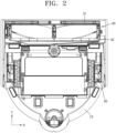
- FIG. 2 is a bottom view of a cleaning device according to an example.
- a cleaning device 1 according to the present embodiment of the disclosure will be described focusing on a robot cleaning device that may independently perform a cleaning operation according to a preset method without relying on the manual operation of the user.
- the disclosure is not limited thereto, and the cleaning device 1 according to the disclosure may be applied to any cleaning device that depends on the manual operation of the user.
- the cleaning device 1 may include a body unit 10, a running unit 20 capable of moving the body unit 10 along one plane, a suction unit 30 for sucking up foreign substances placed on a cleaning target surface H (see FIG. 9 ), and a dust collection container (not illustrated) for accommodating the foreign substances sucked up from the cleaning target surface H.
- the body unit 10 may form the external shape of the cleaning device 1.
- the body unit 10 may be provided in the shape of a housing including an accommodation space therein.
- the body unit 10 may accommodate components for the cleaning device 1 to perform a cleaning operation, in a space accommodated therein.
- a dust collection container (not illustrated) described below may be detachably accommodated inside the body unit 10.
- the internal space of the body unit 10 may communicate with the outside. Accordingly, as the cleaning device 1 runs, the air or small waste collected through the suction unit 30 may be collected into the detachably-coupled dust collection container (not illustrated) through the internal space of the body unit 10.
- the body unit 10 may collide with various obstacles located in an area where the cleaning device 1 runs, for example, an indoor area.
- the body unit 10 may include a high-rigidity material to prevent damage caused by collision.
- the body unit 10 may include a lightweight material. Accordingly, the power required to run the cleaning device 1 may be reduced.
- the body unit 10 may include synthetic resin such as reinforced plastic.
- a user interface may be provided on an external surface of the body unit 10. The user may control an operation of the cleaning device 1 by operating the user interface. Also, the user interface may display information about the state of the cleaning device 1 and the area where the cleaning device 1 runs.
- the body unit 10 may have a disk shape having a circular cross-section and a certain height in the vertical direction. Accordingly, when the cleaning device 1 collides with various obstacles while running, the body unit 10 may rotate and run in various directions.
- the running unit 20 may move the body unit 10 along one plane, for example, the XY plane.
- the running unit 20 may include one or more driving wheels and a running motor for generating power transmitted to the driving wheels.
- the running unit 20 may be rotatably coupled to the lower side of the body unit 10.
- the running unit 20 may be provided as a plurality of running units. In this case, the rotation speed and rotation direction of each of the running units 20 may be controlled independently of each other. Accordingly, the body unit 10 may move forward, move backward, turn left, or turn right on one plane (XY plane).
- a running sensor unit 25 may be arranged to sense information about the path along which the cleaning device 1 runs.
- the running sensor unit 25 may be located in a direction in which the cleaning device 1 is expected to run.
- the running sensor unit 25 may be arranged above the body unit 10 to sense information about the environment on the front side of the cleaning device 1.
- the running sensor unit 25 may be provided in any form capable of sensing information about the environment of the path along which the cleaning device 1 runs.
- the driving sensor unit 25 may include a LIDAR sensor for sensing the distance to an obstacle, or a camera capable of sensing image information.
- the dust collection container (not illustrated) may store the waste collected while the cleaning device 1 runs.
- the dust collection container (not illustrated) may accommodate the contaminants placed on the cleaning target surface H.
- the dust collection container (not illustrated) according to an example may be detachably coupled to the body unit 10. The user may remove the dust collection container (not illustrated) from the body unit 10 to easily remove the contaminants accommodated in the dust collection container (not illustrated).
- the dust collection container (not illustrated) may include an accommodation space therein.
- the accommodation space may communicate with a space formed inside the body unit 10, for example, a movement path.
- the contaminants collected through the suction unit 30 may enter the dust collection container (not illustrated) through the movement path formed inside the body unit 10.
- the suction unit 30 may suck up contaminants by using a suction motor (not illustrated) for generating a suction force necessary to suck up foreign substances on the cleaning target surface H.
- Contaminants sucked up through the suction unit 30 may have different sizes, shapes, and materials.
- a first contaminant T 1 (see FIG. 9 ) sucked up through the suction unit 30 may not be easily separated from the cleaning target surface H after adhering thereto but may have a smaller size than a second contaminant T 2 (see FIG. 10 ) described below.
- the first contaminant T 1 may include hairs removed from human bodies and textile strands separated from clothes or the like.
- a contaminant such as hairs, textile strands, or pet hairs may have the property of easily adhering to an object with a rough surface due to electrostatic attraction. Simultaneously, the contaminant may have the property of not being easily separated from the surface of an object to which it has adhered. Thus, in daily life, when the contaminant adheres to the surface of an object of a textile material such as a carpet or a rug, it may not be easily separated therefrom.
- the second contaminant T 2 (see FIG. 10 ) sucked up through the suction unit 30 may be easily separated from the cleaning target surface H but may have a larger shape than the first contaminant T 1 .
- the second contaminant T 2 may be a small toy or food that does not adhere to the cleaning target surface H.
- the size and suction pressure of the suction unit 30 may vary depending on the type of a contaminant sucked up through the suction unit 30.
- the suction area of the suction unit 30 may be increased to change the size of the suction unit 30.
- the power of the suction motor (not illustrated) may be increased to increase the suction pressure of the suction unit 30.
- the suction pressure of the suction unit 30 may be increased by reducing the suction area of the suction unit 30, or the suction pressure of the suction unit 30 may be reduced by increasing the suction area of the suction unit 30.
- the suction unit 30 into a first suction unit 31 through which the first contaminant T 1 passes and a second suction unit through which the second contaminant T 2 passes and differently adjusting the suction areas and suction pressures of the first suction unit 31 and the second suction unit 32 will be described in more detail.
- FIG. 3 is an exploded perspective view of a cleaning device according to an example.
- FIG. 4 is a block diagram of a cleaning device according to an example.
- FIG. 5 is an exploded perspective view of a suction unit according to an example.
- FIG. 6 is a perspective view of a roller unit, a brush, and a partition unit according to an example.
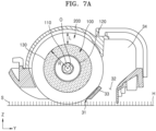
- FIG. 7A is a cross-sectional view of a suction unit according to an example.
- FIG. 7B is an enlarged cross-sectional view of a portion of a suction unit according to an example.
- the suction unit 30 may include the first suction unit 31, the second suction unit 32, and a partition unit 33 arranged therebetween the first suction unit 31 and the second suction unit 32.
- the first suction unit 31 where a roller unit 100 described below is arranged may have a suction area less than the suction area of the second suction unit 32 but may have a suction pressure greater than the suction pressure of the second suction unit 32. Accordingly, the first contaminant T 1 (see FIG. 9 ), which is not easily separated from the cleaning target surface H after adhering thereto but has a smaller size than the second contaminant T 2 , may pass through the first suction unit 31.
- the second suction unit 32 may have a suction area greater than the suction area of the first suction unit 31 but may have a suction pressure less than the suction pressure of the first suction unit 31. Accordingly, the second contaminant T 2 (see FIG. 10 ), which is easily separated from the cleaning target surface H but has a larger shape than the first contaminant T 1 , may pass through the second suction unit 32.
- the first suction unit 31 may be a suction port extending in a first direction (X direction) and may be arranged under the body unit 10.
- the first suction unit 31 may fluidly communicate with a dust collection unit (not illustrated) by using a movement path 34 connected to the dust collection unit (not illustrated). Accordingly, the first contaminant T 1 sucked up through the first suction unit 31 may be accommodated into the dust collection unit (not illustrated) through the movement path 34.
- the first suction unit 31 may include a rectangular opening shape extending in the first direction (X direction).
- the disclosure is not limited thereto, and the first suction unit 31 may include any opening shape through which the first contaminant T 1 may pass.
- the first suction unit 31 may have a relatively high suction pressure.
- the suction pressure of the first suction unit 31 may increase as the suction area of the first suction unit 31 becomes further smaller than the suction area of the second suction unit 32.
- the suction area of the first suction unit 31 may decrease and the suction pressure thereof may increase.
- the roller unit 100 may be connected to the body unit 10 to be rotatable around one axis 110 extending in the first direction (X direction). Both end portions of the roller unit 100 according to an example may be rotatably supported by a side frame 11 provided in the body unit 10, to be rotatable in any one of the clockwise direction or the counterclockwise direction around the one axis 110. As an example, the roller unit 100 may rotate around the one axis 110 at a speed of about 500 revolutions per minute (rpm) to about 1,500 rpm.
- rpm revolutions per minute
- a driving unit 300 may generate power and transmit the same to the roller unit 100 such that the roller unit 100 may rotate around the one axis 110.
- a controller 700 may control the rotation speed and rotation direction of the roller unit 100 by controlling the driving unit 300.
- a sensor unit 500 may be arranged at one or more of each end portion in the direction in which the roller unit 100 extends. The sensor unit 500 may sense rotation-related information such as the rotation direction and rotation angle of the roller unit 100.
- the roller unit 100 may be formed to extend in one direction, for example, in the first direction (X direction).
- the first direction (X direction) may be perpendicular to a direction in which the cleaning device 1 moves forward, for example, a second direction (Y direction).
- a direction in which the cleaning device 1 moves forward for example, a second direction (Y direction).
- the roller unit 100 may have any shape that may rotate around one axis between the side frames 11.
- the cross-section of the roller unit 100 taken in the second direction (Y direction) perpendicular to the first direction (X direction) may have a circular shape 120.
- a radius R of the circular shape 120 measured from a center O of the roller unit 100 may be about 6 mm to about 18 mm.
- the cross-sectional shape of the roller unit 100 is described as a circular shape; however, the disclosure is not limited thereto.
- the cross-sectional shape of the roller unit 100 may have a polygonal shape.
- the roller unit 100 may include a high-rigidity material capable of supporting the brush 200 described below.
- the roller unit 100 may include synthetic resin such as reinforced plastic.
- an outer circumferential surface 130 of the roller unit may be a support member by which one end portion of the brush 200 may be supported.
- the outer circumferential surface 130 of the roller unit 100 may set a boundary range through which a contaminant with a certain size may pass.
- the brush 200 may be arranged on the outer circumferential surface 130 of the roller unit 100.
- the brush 200 may include a plurality of brush structures extending in the radial direction of the roller unit 100.
- a length L of the brush 200 extending in the radial direction of the roller unit 100 from the outer circumferential surface 130 of the roller unit 100 may be about 2.9 mm to about 8.7 mm; however, the disclosure is not limited thereto.
- the support frame 810 may be arranged to be detachable from the lower front side of the body unit 10. According to an example, when the body unit 10 is moved by the running unit 20, the lower side of the support frame 810 may move together with the body unit 10 while contacting the cleaning target surface or being apart therefrom by a certain distance.
- the support frame 810 may be provided in the shape of a frame including an accommodation space therein.
- the support frame 810 may move together by being coupled with the body unit 10 and may have any shape capable of accommodating the roller unit 100 therein.
- the support frame 810 may include a hollow polygonal pillar shape extending long in the horizontal direction.
- the roller unit 100 may be detachably connected to the first suction unit 31 provided in the support frame 810 according to an example.
- the roller unit 100 may be connected to the support frame 810 to be rotatable around the one axis 110.
- both end portions of the roller unit 100 may be detachably connected to the side portion of the support frame 810.
- the bearing unit 820 may be arranged at both end portions of the one axis 110, which is the center axis of the roller unit 100, to support the one axis 110.
- the fastening unit when the roller unit 100 is connected to the support frame 810, the fastening unit (not illustrated) may be fastened to the support frame 810 such that the roller unit 100 is fixed to the support frame 810.
- the fastening unit may be provided in the form of a cap cover that is arranged at both end portions of the roller unit 100 and fastened to the support frame 810.
- FIG. 9 is a cross-sectional view of a suction unit through which contaminants are sucked up, according to an example.
- FIG. 10 is a cross-sectional view of a suction unit through which contaminants are sucked up, according to an example.
- the cleaning target surface H where the cleaning device 1 according to an example moves may include a textile material S such as a carpet or a rug.
- the first contaminant T 1 with high adhesion such as hairs, textile strands, or pet hairs, may be easily adhered by electrostatic attraction to the textile material S included in an object with a rough surface, such as a carpet or a rug. Simultaneously, the first contaminant T 1 may not be easily separated from the surface of the textile material S to which the first contaminant T 1 has been adhered.
- the brush 200 may be modified to correspond to the shape of the cleaning target surface H and the textile material S.
- the first contaminant T 1 such as hair located on the cleaning target surface H and the textile material S may adhere to the modified brush 200 and move to the first suction unit 31.
- a portion of the brush 200 arranged on the outer circumferential surface 130 of the roller unit 100 and the partition unit 33 may be arranged to overlap each other.
- the suction area of the first suction unit 31 may be reduced.
- the suction pressure of the first suction unit 31 may increase.
- the area of the first suction unit 31 may be maintained within the range of the first distance D between the roller unit 100 and the partition unit 33.
- the first contaminant T 1 such as animal hair with high adhesion may be sucked up through the first suction unit 31.
- the boundary range through which the second contaminant T 2 may pass in the second suction unit 32 may be the width P of the second suction unit 32.
- the width P of the second suction unit 32 may be greater than the first distance D between the roller unit 100 and the partition unit 33. Accordingly, the second suction unit 32 may have a relatively large suction area compared to the first suction unit 31.
- the second suction unit 32 having a relatively large suction area may have a relatively low suction pressure.
- the second contaminant T 2 which is easily separated from the cleaning target surface H but has a larger shape than the first contaminant T 1 , may be sucked up through the second suction unit 32.
- a cleaning device may include a body unit 10 movable along one plane, a first suction unit 31 extending in a first direction and arranged under the body unit, a second suction unit 32 extending in the first direction and arranged under the body unit, a partition unit 33 extending in the first direction and arranged between the first suction unit and the second suction unit, a roller unit 100 arranged in the first suction unit, extending in the first direction, and arranged to be rotatable around one axis extending in the first direction, a brush 200 extending by a certain length from an outer circumferential surface of the roller unit, and a driving unit 300 configured to generate power such that the roller unit rotates around the one axis, wherein the outer circumferential surface of the roller unit and the partition unit may be arranged to be spaced apart from each other by a first distance, and the certain length of the brush may be greater than the first distance.
- the partition unit 33 may be arranged to be inclined to have a first angle with respect to the one plane.
- the first angle may be about 15 degrees to about 75 degrees.
- One end portion of the partition unit 33 may be arranged at a height of about 0.5 mm to about 3 mm above another end portion of the brush 200 located at a lowest end portion in a thickness direction of the cleaning device.
- a width of the second suction unit 32 in a second direction perpendicular to the first direction may be greater than the first distance between the outer circumferential surface of the roller unit 100 and the partition unit 33.
- the first distance between the outer circumferential surface of the roller unit 100 and the partition unit 33 may be about 1 mm to about 5.2 mm.
- a width of the second suction unit 32 in a second direction perpendicular to the first direction may be about 4 mm to about 20 mm.
- the cleaning device may further include a support frame 810 in which the first suction unit 31, the second suction unit 32, and the partition unit 33 are arranged and which is detachable from the body unit 10, wherein the roller unit 100 may be arranged to be rotatable around the one axis with respect to the support frame 810.
- the support frame 810 and the partition unit 33 may be integrally provided with each other.
- the cleaning device may further include a bearing unit 820 arranged at both end portions of the one axis to support the one axis.
- a cross-section of the roller unit 100 taken in a second direction perpendicular to the first direction may include a circular shape, a radius of the circular shape may be about 6 mm to about 18 mm, and a length of the brush extending in a radial direction of the roller unit may be about 2.9 mm to about 8.7 mm.
- the roller unit 100 may rotate around the one axis at a speed of about 500 rpm to about 1,500 rpm.
- the cleaning device may further include a sensor unit 500 configured to sense a rotation speed of the roller unit, and a controller 700 configured to control an operation of the driving unit by receiving the rotation speed of the roller unit from the sensor unit.
Landscapes
- Engineering & Computer Science (AREA)
- Mechanical Engineering (AREA)
- Nozzles For Electric Vacuum Cleaners (AREA)
Applications Claiming Priority (2)
| Application Number | Priority Date | Filing Date | Title |
|---|---|---|---|
| KR1020220151985A KR20240070293A (ko) | 2022-11-14 | 2022-11-14 | 청소 장치 |
| PCT/KR2023/017999 WO2024106852A1 (fr) | 2022-11-14 | 2023-11-09 | Appareil de nettoyage |
Publications (2)
| Publication Number | Publication Date |
|---|---|
| EP4548826A1 true EP4548826A1 (fr) | 2025-05-07 |
| EP4548826A4 EP4548826A4 (fr) | 2025-10-01 |
Family
ID=91029263
Family Applications (1)
| Application Number | Title | Priority Date | Filing Date |
|---|---|---|---|
| EP23891919.5A Pending EP4548826A4 (fr) | 2022-11-14 | 2023-11-09 | Appareil de nettoyage |
Country Status (3)
| Country | Link |
|---|---|
| US (1) | US20240156314A1 (fr) |
| EP (1) | EP4548826A4 (fr) |
| CN (1) | CN119855529A (fr) |
Family Cites Families (7)
| Publication number | Priority date | Publication date | Assignee | Title |
|---|---|---|---|---|
| DE1138526B (de) * | 1957-10-07 | 1962-10-25 | Amica Produkter | Anordnung zur Lagerung von Walzenbuersten fuer Kehrmaschinen |
| EP2117402B1 (fr) * | 2006-12-13 | 2015-05-27 | Aktiebolaget Electrolux | Dispositif de nettoyage du sol humide/sec |
| KR20100132891A (ko) * | 2009-06-10 | 2010-12-20 | 삼성광주전자 주식회사 | 청소장치 및 이를 이용한 먼지 포집 방법 |
| EP2570067A1 (fr) * | 2011-09-01 | 2013-03-20 | Samsung Electronics Co., Ltd. | Appareil de nettoyage autonome et son procédé de commande |
| US11019975B2 (en) * | 2016-07-14 | 2021-06-01 | Lg Electronics Inc. | Robot cleaner |
| CN211355206U (zh) * | 2019-07-24 | 2020-08-28 | 天佑电器(苏州)有限公司 | 吸尘地刷及具有其的吸尘器 |
| CN114190842A (zh) * | 2021-12-17 | 2022-03-18 | 珠海格力电器股份有限公司 | 清洁设备及其机身 |
-
2023
- 2023-11-09 CN CN202380068027.1A patent/CN119855529A/zh active Pending
- 2023-11-09 EP EP23891919.5A patent/EP4548826A4/fr active Pending
- 2023-11-13 US US18/507,813 patent/US20240156314A1/en active Pending
Also Published As
| Publication number | Publication date |
|---|---|
| EP4548826A4 (fr) | 2025-10-01 |
| US20240156314A1 (en) | 2024-05-16 |
| CN119855529A (zh) | 2025-04-18 |
Similar Documents
| Publication | Publication Date | Title |
|---|---|---|
| US12042118B2 (en) | Robot cleaner, station, and cleaning system | |
| RU2423905C2 (ru) | Робот-пылесос | |
| US10258212B2 (en) | Cleaner | |
| JP6167316B2 (ja) | 自律走行型掃除機 | |
| KR101688292B1 (ko) | 자주식 전자 장치 | |
| EP4388962A1 (fr) | Station de base et système de robot de nettoyage | |
| KR101966083B1 (ko) | 로봇 걸레청소기 | |
| JP6888847B2 (ja) | 自走式掃除機 | |
| KR20210037802A (ko) | 로봇 청소기 | |
| JP2014094233A (ja) | 電気掃除装置 | |
| TWI892643B (zh) | 清潔機器人 | |
| US20230320548A1 (en) | Nozzle unit, robot cleaner including same, and control method therefor | |
| EP4548826A1 (fr) | Appareil de nettoyage | |
| EP4505930A1 (fr) | Robot de nettoyage | |
| EP4505932A1 (fr) | Aspirateur robot | |
| KR20240070293A (ko) | 청소 장치 | |
| EP4505931A1 (fr) | Robot de nettoyage | |
| US20240023771A1 (en) | Cleaning device and operation method thereof | |
| KR20240012980A (ko) | 청소 장치 및 청소 장치의 작동 방법 | |
| JP7264671B2 (ja) | 電気掃除機 | |
| KR20120112292A (ko) | 로봇청소기 | |
| US20250241502A1 (en) | Cleaning robot | |
| KR20070105124A (ko) | 자동 청소기 | |
| JP6941764B2 (ja) | 自律走行型掃除機 | |
| KR20070105411A (ko) | 자동 청소기 |
Legal Events
| Date | Code | Title | Description |
|---|---|---|---|
| STAA | Information on the status of an ep patent application or granted ep patent |
Free format text: STATUS: THE INTERNATIONAL PUBLICATION HAS BEEN MADE |
|
| PUAI | Public reference made under article 153(3) epc to a published international application that has entered the european phase |
Free format text: ORIGINAL CODE: 0009012 |
|
| STAA | Information on the status of an ep patent application or granted ep patent |
Free format text: STATUS: REQUEST FOR EXAMINATION WAS MADE |
|
| 17P | Request for examination filed |
Effective date: 20250130 |
|
| AK | Designated contracting states |
Kind code of ref document: A1 Designated state(s): AL AT BE BG CH CY CZ DE DK EE ES FI FR GB GR HR HU IE IS IT LI LT LU LV MC ME MK MT NL NO PL PT RO RS SE SI SK SM TR |
|
| A4 | Supplementary search report drawn up and despatched |
Effective date: 20250903 |
|
| RIC1 | Information provided on ipc code assigned before grant |
Ipc: A47L 9/04 20060101AFI20250828BHEP Ipc: A47L 9/28 20060101ALI20250828BHEP Ipc: A47L 7/02 20060101ALI20250828BHEP |
|
| DAV | Request for validation of the european patent (deleted) | ||
| DAX | Request for extension of the european patent (deleted) |