EP4548862A1 - Chirurgisches klammergerät mit klemmkraftsensor - Google Patents
Chirurgisches klammergerät mit klemmkraftsensor Download PDFInfo
- Publication number
- EP4548862A1 EP4548862A1 EP24209400.1A EP24209400A EP4548862A1 EP 4548862 A1 EP4548862 A1 EP 4548862A1 EP 24209400 A EP24209400 A EP 24209400A EP 4548862 A1 EP4548862 A1 EP 4548862A1
- Authority
- EP
- European Patent Office
- Prior art keywords
- anvil
- cartridge
- end effector
- communication module
- sensing component
- Prior art date
- Legal status (The legal status is an assumption and is not a legal conclusion. Google has not performed a legal analysis and makes no representation as to the accuracy of the status listed.)
- Pending
Links
Images












Classifications
-
- A—HUMAN NECESSITIES
- A61—MEDICAL OR VETERINARY SCIENCE; HYGIENE
- A61B—DIAGNOSIS; SURGERY; IDENTIFICATION
- A61B17/00—Surgical instruments, devices or methods
- A61B17/068—Surgical staplers, e.g. containing multiple staples or clamps
- A61B17/072—Surgical staplers, e.g. containing multiple staples or clamps for applying a row of staples in a single action, e.g. the staples being applied simultaneously
-
- A—HUMAN NECESSITIES
- A61—MEDICAL OR VETERINARY SCIENCE; HYGIENE
- A61B—DIAGNOSIS; SURGERY; IDENTIFICATION
- A61B17/00—Surgical instruments, devices or methods
- A61B2017/00017—Electrical control of surgical instruments
- A61B2017/00022—Sensing or detecting at the treatment site
-
- A—HUMAN NECESSITIES
- A61—MEDICAL OR VETERINARY SCIENCE; HYGIENE
- A61B—DIAGNOSIS; SURGERY; IDENTIFICATION
- A61B17/00—Surgical instruments, devices or methods
- A61B2017/00017—Electrical control of surgical instruments
- A61B2017/00115—Electrical control of surgical instruments with audible or visual output
- A61B2017/00119—Electrical control of surgical instruments with audible or visual output alarm; indicating an abnormal situation
-
- A—HUMAN NECESSITIES
- A61—MEDICAL OR VETERINARY SCIENCE; HYGIENE
- A61B—DIAGNOSIS; SURGERY; IDENTIFICATION
- A61B17/00—Surgical instruments, devices or methods
- A61B2017/00017—Electrical control of surgical instruments
- A61B2017/00221—Electrical control of surgical instruments with wireless transmission of data, e.g. by infrared radiation or radiowaves
-
- A—HUMAN NECESSITIES
- A61—MEDICAL OR VETERINARY SCIENCE; HYGIENE
- A61B—DIAGNOSIS; SURGERY; IDENTIFICATION
- A61B17/00—Surgical instruments, devices or methods
- A61B2017/00526—Methods of manufacturing
-
- A—HUMAN NECESSITIES
- A61—MEDICAL OR VETERINARY SCIENCE; HYGIENE
- A61B—DIAGNOSIS; SURGERY; IDENTIFICATION
- A61B17/00—Surgical instruments, devices or methods
- A61B2017/00681—Aspects not otherwise provided for
- A61B2017/00734—Aspects not otherwise provided for battery operated
-
- A—HUMAN NECESSITIES
- A61—MEDICAL OR VETERINARY SCIENCE; HYGIENE
- A61B—DIAGNOSIS; SURGERY; IDENTIFICATION
- A61B17/00—Surgical instruments, devices or methods
- A61B17/068—Surgical staplers, e.g. containing multiple staples or clamps
- A61B17/072—Surgical staplers, e.g. containing multiple staples or clamps for applying a row of staples in a single action, e.g. the staples being applied simultaneously
- A61B2017/07214—Stapler heads
- A61B2017/07221—Stapler heads curved
-
- A—HUMAN NECESSITIES
- A61—MEDICAL OR VETERINARY SCIENCE; HYGIENE
- A61B—DIAGNOSIS; SURGERY; IDENTIFICATION
- A61B17/00—Surgical instruments, devices or methods
- A61B17/068—Surgical staplers, e.g. containing multiple staples or clamps
- A61B17/072—Surgical staplers, e.g. containing multiple staples or clamps for applying a row of staples in a single action, e.g. the staples being applied simultaneously
- A61B2017/07214—Stapler heads
- A61B2017/07257—Stapler heads characterised by its anvil
-
- A—HUMAN NECESSITIES
- A61—MEDICAL OR VETERINARY SCIENCE; HYGIENE
- A61B—DIAGNOSIS; SURGERY; IDENTIFICATION
- A61B17/00—Surgical instruments, devices or methods
- A61B17/068—Surgical staplers, e.g. containing multiple staples or clamps
- A61B17/072—Surgical staplers, e.g. containing multiple staples or clamps for applying a row of staples in a single action, e.g. the staples being applied simultaneously
- A61B2017/07214—Stapler heads
- A61B2017/07271—Stapler heads characterised by its cartridge
-
- A—HUMAN NECESSITIES
- A61—MEDICAL OR VETERINARY SCIENCE; HYGIENE
- A61B—DIAGNOSIS; SURGERY; IDENTIFICATION
- A61B90/00—Instruments, implements or accessories specially adapted for surgery or diagnosis and not covered by any of the groups A61B1/00 - A61B50/00, e.g. for luxation treatment or for protecting wound edges
- A61B90/06—Measuring instruments not otherwise provided for
- A61B2090/064—Measuring instruments not otherwise provided for for measuring force, pressure or mechanical tension
-
- A—HUMAN NECESSITIES
- A61—MEDICAL OR VETERINARY SCIENCE; HYGIENE
- A61B—DIAGNOSIS; SURGERY; IDENTIFICATION
- A61B2562/00—Details of sensors; Constructional details of sensor housings or probes; Accessories for sensors
- A61B2562/02—Details of sensors specially adapted for in-vivo measurements
- A61B2562/0261—Strain gauges
Definitions
- An illustrative stapling instrument may include a pair of cooperating elongate jaw members, where each jaw member may be adapted to be inserted into a patient and positioned relative to tissue that is to be stapled and/or incised.
- One of the jaw members may support a staple cartridge with at least two laterally spaced rows of staples contained therein, and the other jaw member may support an anvil with staple-forming pockets aligned with the rows of staples in the staple cartridge.
- the stapling instrument may further include a pusher bar and a knife blade that are slidable relative to the jaw members to sequentially or simultaneously eject the staples from the staple cartridge via camming surfaces on the pusher bar and/or camming surfaces on a wedge sled that is pushed by the pusher bar.
- the camming surfaces may be configured to activate one or more staple drivers carried by the cartridge and associated with the staples in order to push the staples against the anvil and form laterally spaced rows of deformed staples in the tissue gripped between the jaw members.
- Such rows may be arranged as linear rows and/or arcuate rows for sequentially or simultaneously stapling and cutting the tissue of the patient in the form of a predetermined pattern.
- the knife blade may trail the camming surfaces and cut the tissue along a linear or arcuate line between the rows of staples formed in the tissue.
- a surgical stapler may be inserted into a patient to perform colorectal surgery. Such procedures may include the use of the stapler to operatively seal, sever, and remove the colon of the patient, in whole or in part. For instance, a proctocolectomy may be performed during a lower anterior resection ("LAR") for treating and inhibiting the spread of colorectal cancer cells.
- LAR anterior resection
- surgical staplers may be used in various other settings and procedures.
- proximal and distal are defined herein relative to a human or robotic operator of the surgical instrument.
- proximal refers the position of an element closer to the human or robotic operator of the surgical instrument and further away from the surgical end effector of the surgical instrument.
- distal refers to the position of an element closer to the surgical end effector of the surgical instrument and further away from the human or robotic operator of the surgical instrument.
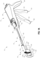
- FIG. 1A depicts an illustrative surgical stapling and severing instrument (10) that includes a handle assembly (12), a shaft assembly (14), and an end effector (16) distally projecting from shaft assembly (14).
- proximal distal
- distal distal
- end effector (16) is distal with respect to the relatively proximal handle assembly (14).
- instrument (10) may be configured and operable in accordance with at least some of the teachings of U.S. Pat. Pub. No. 2005/0143759, entitled “Curved Cutter Stapler Shaped for Male Pelvis,” published on June 30, 2005 , the disclosure of which is incorporated by reference herein; U.S. Pat. No. 10,045,780, entitled “Method of Applying Staples in Lower Anterior Bowel Resection,” issued August 14, 2018 , the disclosure of which is incorporated by reference herein; U.S. Pat. No.
- Handle assembly (12) includes several actuation mechanisms for operating end effector (16) during the surgical procedure.
- illustrative handle assembly (12) includes a saddle shaped slide (18), a closure trigger (20), and a firing trigger (22) in communication with end effector (16) via shaft assembly (14).
- slide (18) and closure trigger (20) are in open configurations such that end effector (16) is configured to receive tissue laterally within a gap (25) between an anvil (26) and a cartridge (28) of end effector (16).
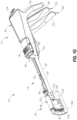
- Translating slide (18) distally toward end effector (16) slides a retaining pin (30) of end effector distally as shown in FIG. 1B for capturing the tissue between anvil (26) and cartridge (28).
- sequentially actuating closure trigger (20) and firing trigger (22) respectively compresses the tissue between anvil (26) and cartridge (28) in a closed configuration and then forms a plurality of staples (not shown) within the tissue and severs the tissue with a knife (32) (see FIG. 6 ) for treatment. Additional details regarding these illustrative actuation mechanisms will be provided below in greater detail.
- handle assembly (12) has a handle housing (34), a pair of handle frame plates (35, 36) within handle housing (34) extending along shaft assembly (14), saddle shaped slide (18), closure trigger (20), and firing trigger (22) as briefly discussed above.
- Handle housing (34) defines a hand grip (38), which the operator, such as a surgeon, grasps with the palm of at least one hand.
- Handle housing (34) is formed by a right shroud handle portion (40) and a left shroud handle portion (42).
- Closure trigger (20) is proximally positioned relative to firing trigger (22) and each are pivotally mounted to frame plates (35, 36) to extend underneath a remainder of handle assembly (12) for manipulation by the fingers of the operator.
- Closure and firing triggers (20, 22) are shown in unactuated positions prior to closing end effector (16) and firing staples (not shown) and/or knife (32) ( see FIG. 6 ). Consequently, cartridge (28) is spaced from anvil (26) for receiving tissue within gap (25) therebetween.
- FIG. 1A shows retaining pin actuation mechanism (37), which includes slide (18), in the open configuration
- FIG. 2A shows retaining pin actuation mechanism (37) in the closed configuration in greater detail
- slide (18) is mounted on an upper surface of handle housing (34) and is configured to linearly translate between proximal and distal positions.
- Slide (18) connects to posts (44), which extend laterally outwardly from a push rod driver (46), through slots (48) ( see FIG. 1A ).
- Push rod driver (46) is restrained within handle housing (34) along longitudinal movement by slots (48).
- Push rod driver (46) is connected to a proximal end of a push rod (50).
- a distal end of push rod (50) connects to retaining pin (30) ( see FIG. 6 ) such that distal movement of slide (18) causes push rod (50) to similarly slide proximally along shaft assembly (14) for moving retaining pin (30) ( see FIG. 6 ) to the closed configuration, which will be discussed below in greater detail.
- Closure mechanism (52) further includes an elongated closure member (54), with a generally U-shaped cross-section, extending distally from handle assembly (12), through shaft assembly (14), and into end effector (16) for receiving a cartridge (28) ( see FIG. 3 ) at a distal end portion thereof as discussed below.
- a proximal end portion of closure member (54) is operatively connected to closure trigger (20) by a plurality of linkages configured to convert pivoting motion of closure trigger (20) into translation of closure member (54).
- closure member (54) extend through handle assembly (12) between left and right handle frame plates (35, 36).
- Right and left closure links (56) are respectively pivotally attached at the right and left proximal ends of closure member (54) by an integral closure link pin (58).
- closure links (56) are pivotally attached to another integral closure link pin (60).
- Closure link pin (60) connects closure links (56) to a slotted closure arm link (62), which is pivotally mounted to handle frame plates (35, 36) at a closure trigger pin (64).
- Closure trigger (20) descends from the slotted closure arm link (62) for pivotal rotation about closure trigger pivot pin (64) both toward and away from hand grip (38).
- a closure spring (66) housed within hand grip (38) is secured to the slotted closure arm link (62) to provide a desired resistance when the operator squeezes closure trigger (20) toward hand grip (38), and to bias closure trigger (20) toward the open position.
- Closure member (54) is further configured for directing movement of tissue retaining pin actuation mechanism (37) to automatically direct movement of the retaining pin (30) to the closed configuration while the operator squeezes closure trigger (20). Such automation may be useful in the event that the operator did not manually move the slide (18) to the distal position before actuating trigger (20).
- Closure member (54) includes posts (68), which extend laterally on each opposing side of closure member (54) within handle housing (34). Posts (68) slidably connect to a yoke (70) via L-shaped slots (72). Yoke (70) is pivotally mounted within handle housing (34) by a pivot pin (74). Yoke (70) further includes cam pins (76) that are configured to push camming surfaces (78) on push rod driver (46).
- actuating closure trigger (20) to an intermediate position shown in FIG. 2A directs the closure member (52) distally and, in turn, causes yoke (70) to engage push rod driver (46) and force retaining pin (30) ( see FIG. 1B ) to the closed position.
- Slide (18) is thereby dragged along handle housing (34) from the proximal position to the distal position in the event that the operator did not manually manipulate slide (18) to the distal position before actuating trigger (20).
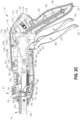
- Illustrative handle assembly (12) is configured to form the staples (not shown) and sever the tissue via a firing mechanism (80) upon operator manipulation of firing trigger (22) toward closure trigger (20) as shown in FIGS. 1D and 2C .
- firing mechanism (80) which includes firing trigger (22) has a firing bar (82) extending distally from handle assembly (12) and within end effector (16). A distal end of firing bar (82) cooperates with cartridge (28) as discussed below in greater detail, whereas a proximal end of firing bar (82) is operatively connected to firing trigger (80) for selective firing thereof.
- Firing bar (82) has a rectangular receiving slot (84) ( see FIG. 2A ) in a portion of firing bar (82) positioned within handle housing (34). Integral closure link pin (58) extends through receiving slot (84). The underside of the proximal end portion of firing bar (82) has a sliding surface (86). The proximal end portion of firing bar (82) also has a terminal side engagement surface (82) extending from sliding surface (86). Firing trigger (22) is pivotally mounted to handle frame plates (35, 36) by a firing trigger pin (90) spaced from closure trigger pin (64) such that each of pins (90, 64) pivot about mutually independent axes.
- Firing trigger (22) includes an arcuate firing trigger link (92) extending from firing trigger (22) at firing trigger pin (90) to an apex (94), which rests on sliding surface (86) of the proximal end portion of firing bar (82).
- firing trigger (22) is attached to firing trigger spring arms (95, 96), respectively.
- Firing trigger spring arms (95, 96) support a torsion spring (not shown) on the right half of firing trigger (22).
- a firing bar return spring (98) is secured to the underside of firing bar (82) at the portion of firing bar (82) within handle assembly (12) to bias firing bar (82) toward its unactuated position.
- closure trigger (20) toward hand grip (38) slotted closure arm link (62) and closure links (56) move distally within receiving slot (84) of firing bar (82).
- This distal movement causes closure member (54) to correspondingly move distally.
- firing bar (82) concurrently moves distally with closure member (54), because integral closure link pin (58), to which closure links (56) are attached, extends through receiving slot (84) in firing bar (82) (see FIG. 2A ).
- firing bar (82) is forced distally to form the staples (not shown) in the tissue and/or sever the tissue with knife (32) (see FIG. 6 ).
- firing trigger (22) may fully squeeze firing trigger (22) toward hand grip (38) to "fire” surgical stapling instrument (10) and force firing bar (82) further distally to form the staples (not shown) and sever the tissue.
- This distal movement of firing bar (82) may also be referred to herein as “firing” the firing bar (82) to the actuated or "fired” position.
- surgical stapling instrument (10) may be further configured to releasably lock in one of a variety of configurations. The operator may then release the hand grip (38) to free one or more hands for another task during the surgical procedure and, when desired, release surgical stapling instrument (10) from its locked position by release button (24).
- surgical stapling instrument (10) has an intermediate closure detent position and a closure detent position.
- the top side of the slotted closure arm link (62) has a clamp sliding surface (102) that displays an intermediate detent (104) and a closure detent (106).
- a release pawl (108) slides on clamp sliding surface (102) and may engage intermediate and closure detents (104,106).
- Release pawl (108) has a laterally extending pawl lug (110) at its distal end.
- Release pawl (108) is located within handle assembly (12) and is integrally formed with release button (24), which is situated exterior of handle housing (34) for manipulation by the operator.
- Release button (24) has a thumb rest (112) pivotally attached to handle housing (34) by a release trunnion (114).
- Release button (24) is biased outwardly from handle housing (34) and, therefore, release pawl (108) is biased downwardly toward clamp sliding surface (102) by a release spring (116).
- Release spring (116) is mounted to handle housing (34) by a spring retention pin (118) and is mounted to release button (24) by a button spring post (120).
- Slotted closure arm link (62) has an arcuate recess (122) located between intermediate and closure detents (104, 106). Resting within arcuate recess (122) for rotational movement are integrally connected left and right hand toggles (124).
- Each toggle (124) has a toggle arm (126) that is engageable with pawl lug (110).
- toggle arms (126) from pawl lug (110) disengage from pawl lug (110) as closure trigger (20) is squeezed toward hand grip (38). Consequently, as toggle (124) continues to rotate in a clockwise direction, release pawl lug (108) rides up toggle arms (126) and, with continued motion of closure trigger (20), falls into one of intermediate and closure detents (104, 106), depending on the position of closure trigger (20) in use. As release pawl (108) rides up toggle arm (126), release pawl (108) rotates release button (24) clockwise. Release pawl (108) thereby falls into one of intermediate and detents (104, 106) and generates an audible clicking sound alerting the surgeon that one of the intermediate and closure positions have been reached.
- release button (24) In order to release handle assembly (12) from the intermediate or closure positions discussed herein, the surgeon depresses release button (24). In turn, release pawl (108) pivots about release trunnion (114) in a clockwise direction to dislodge pawl lug (110) from one of the intermediate and closure detents (104, 106). As pawl lug (110) is dislodged, pawl lug (110) rides on toggle arms (126) to another position, such as the unactuated position. Therefore, the operator may release closure and firing triggers (20, 22) such that each may return to the unactuated positions FIG. 1A and FIG. 3 .
- Surgical stapling instrument (10) of the present example includes each of handle frame plates (35, 36), push rod (50), closure member (54), and firing bar (82) extending continuously from handle assembly (12) to end effector (16), thereby defining shaft assembly (14) extending therebetween.
- Handle frame plates (35, 36), push rod (50), closure member (54), and firing bar (82) of surgical stapling instrument (10) provide merely a subset of elongated components extending distally from handle assembly (12) as shaft assembly (14).
- shaft assembly (14) may include additional components, such as an articulating joint, or may include a rearrangement of various components such that shaft assembly (14) may be modular relative to handle assembly (12).
- handle assembly (12) and shaft assembly (14) may have a variety of other components, features, and operabilities, in addition to or in lieu of any of those noted above.
- Other suitable configurations for handle and shaft assemblies (12, 14) will be apparent to those of ordinary skill in the art in view of the teachings herein.
- end effector (16) of the present example includes anvil (26), replaceable cartridge (28) including a plurality of staples (not shown) and knife (32) ( see FIG. 6 ), and retainer pin (30). While end effector (16) of the present example is adapted for use in conjunction with replaceable cartridge (28) having various components, it will be appreciated that the concepts underlying the present invention could be applied to a variety of end effector and cartridge constructions for treating the patient.
- End effector (16) provides a surgical fastening assembly that includes cartridge (28) received within a C-shaped supporting structure (128).
- C-shaped is used throughout the specification to describe the concave nature of supporting structure (128) and cartridge (28).
- the C-shaped construction facilitates enhanced functionality and access to tissue within the patient.
- C-shaped as used herein should be construed to include a variety of concave shapes that would similarly enhance the functionality of surgical stapling and cutting instruments.
- the C-shape of supporting structure (128) may be sized to promote access to the lower colon within the pelvic bowl of a patient, such as to perform a LAR in a proctocolectomy procedure.
- Supporting structure (128) of end effector (16) is respectively attached to handle frame plates (35, 36) of shaft assembly (14) by a shoulder rivet (129) and posts (130) which extend from supporting structure (128) into receiving holes in handle frame plates (35, 36).
- the distal end of closure member (54) is disposed to receive cartridge (28) thereon for directing cartridge (28) to the closed configuration.
- cartridge (28) further includes a safety lockout mechanism (131) ( see FIG. 7A ) configured to inhibit inadvertently re-firing cartridge (28).
- Safety lockout mechanism (131) will be discussed below in additional detail.
- Cartridge (28) includes anvil (26) coupled to a cartridge housing (132).
- Cartridge (28) also includes retaining pin (30) and a tissue contacting surface (34), which defines a plurality of staple-containing slots (136) in staggered formation in one or more rows on either side of knife (32) ( see FIG. 6 ).
- Staples (not shown) are fired from cartridge housing (132) against a staple-forming surface (138) of anvil (26) that faces tissue-contacting surface (134) of cartridge housing (132).
- Cartridge (28) may also include a removable retainer (not shown) for storage between anvil (26) and tissue contacting surface (34) prior to and/or after use in order to inhibit unintended contact with various portions of cartridge (28).
- cartridge (28) includes a staple driver assembly (140) within cartridge housing (132) and proximally positioned behind the plurality of staples (not shown) within staple-containing slots (136).
- Driver assembly (140) of the present example is formed as a unitary structure of a plurality of staple drivers (141).
- the term "assembly” is not intended to be limited to an assembly of individual components but may also include integrally formed components with unitary structures.
- Driver assembly (140) is configured to push the staples (not shown) respectively out of staple containing slots (136) and toward anvil (26) for formation.
- a knife holder (142) is disposed immediately proximal of driver assembly (140) in cartridge housing (132) and defines a slot (144) and ledge (146) for interaction with a knife retractor hook (148) ( see FIG. 10B ), which is discussed below in greater detail.
- Knife holder (142) is attached to knife (32) such that knife (32) extends distally from knife holder (142) through a slot (150) in driver assembly (140) and through another slot (152) in cartridge housing (132).
- knife (32) is disclosed as being within cartridge housing (132) in the present example, other configurations may also be used.
- cartridge (28) may alternatively not include knife (32) for alternative treatments.
- Knife holder (142) has a detent post (154) that extends through a slot (155) in cartridge housing (132). Detent post (154) is positioned in order to contact a detent protrusion (156) of cartridge slot (155) during the longitudinal travel of knife (132) and knife holder (142). Similarly, driver assembly (140) has a detent post (158) positioned in order to contact proximal and distal detent protrusions (159, 160) of cartridge slot (155).
- Knife (32) and slots (150, 152) are positioned such that there is at least one row of staples (not shown) on either side of knife (132).
- two rows of staple slots (136) containing respective rows of staples (not shown) are provided on each side of slot (152) of cartridge housing (132).
- Cartridge housing (132) defines two longitudinally extending, generally circular holes (162, 164) at respective ends of knife slot (152). More particularly, hole (162) at a lower portion of cartridge housing (132) is shaped and dimensioned to receive a guide pin (166) through cartridge housing (132). Hole (164) at an upper portion of cartridge housing (132) is shaped and dimensioned to slidably receive retaining pin (30) through cartridge housing (132). Staple slots (136) of the present example are arranged such that the staples (not shown) laterally extend past the generally circular holes (162, 164).
- Anvil (26) of the present example includes a plastic cutting washer (168) and a metallic staple-forming surface (138). Anvil (26) is disposed to maintain staple-forming surface (138) in alignment with the staples (not shown) to receive and form the staples (not shown) thereon.
- Retaining pin (30) is connected to a couplet (170) by a circumferential slot (172) in retaining pin (30) and a groove (not shown) in couplet (170).
- Couplet (170) is disposed within an arm (176) of cartridge housing (132) and is secured to arm (176) by an end cap (178).
- Guide pin (166) and retaining pin (30) include respective slots (180, 182) ( see also FIGS. 8-9 ) into which lower and upper ends (184, 186) of knife (32) are slidably disposed.
- a proximal end (188) of guide pin (166) is connected to anvil (26), whereas a distal end (190) of guide pin (166) extends from cartridge housing (132) and extends through a slot (192) in anvil (26).
- Cutting washer (168) slips onto anvil (26) via groove (194). Thereby, cutting washer (168) is configured to trap guide pin (166) in the opening formed by slot (192) in anvil (26) and a cutting surface (157) of anvil (26) for connecting anvil (26) to cartridge housing (132).
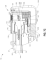
- Lockout mechanism (131) is shown in FIG. 7A in greater detail. Lockout mechanism (131) is configured to inhibit full proximal movement of cartridge housing (132) to its unactuated position after firing.
- lockout mechanism (131) of the present example includes a lockout lever (196) that is pivotally mounted to the distal end of closure member (54) by a pin (198). Lockout lever (196) is spring biased toward the proximal end portion of supporting structure (128) by a spring (not shown).
- a proximal end portion of lockout lever (196) has a cam surface (200) and a locking groove (202).
- Supporting structure (128) of end effector (16) also has a ledge (204) that is configured to cooperate with locking groove (202) when lockout mechanism (131) is engaged.
- supporting structure (128) has a base surface (206) configured to cooperate with cam surface (200) when lockout lever (131) is not engaged.
- cartridge (28) is driven toward anvil (26) via closure member (54) until reaching the closed configuration with tissue positioned between cartridge (28) and anvil (26) as discussed above with respect to handle assembly (12). From the closed configuration, knife (32) and staple driver assembly (140) are further moved toward anvil (26) via firing bar (82) to form staples (not shown) in the tissue, fluidly seal the tissue, and sever the tissue for treating the patient. While actuation of cartridge (28) includes stapling and severing tissue in this example, it will be appreciated that one or more of these steps may be omitted from treatment as desired by the operator. Moreover, it will be appreciated that surgical stapling instrument (10) may be reconfigured to perform these steps simultaneously or sequentially as desired.
- surgical stapling instrument (10) may be reconfigured to selectively fire one of staples (not shown) or knife (32), or selectively fire staples (not shown) and then knife (32), or vice versa. It should therefore be understood that the invention is not intended to be limited to the particular operation of surgical stapling instrument (10) or the associated treatment.
- cartridge (28) is spaced proximally from anvil (26) to receive tissue within gap (25) in the open configuration.
- the operator manually directs push rod (50) distally via slide (18) as discussed above and shown in FIG. 7B .
- Push rod (50) is operatively connected to couplet (70) ( see FIG. 6 ), which is connected to retaining pin (30).
- couplet (70) see FIG. 6
- retaining pin (30) retaining pin
- closure member (54) forces closure member (54) to translate distally relative to supporting structure (128) of end effector (16).
- Closure member (54) supports cartridge (28) thereon such that distal translation of closure member (54) similarly moves firing bar (82) and cartridge (28) toward anvil (26).
- firing trigger (22) see FIG. 1D
- Distal translation of firing bar (82) causes firing bar (82) to engage knife holder (142), which supports both driver assembly (140) and knife (32) extending through driver assembly (140) as shown in FIG. 7D .
- driver assembly (140) directs staples (not shown) from staple slots (136) and against staple-forming surface (138) to form the staples (not shown) within the tissue for fluidly sealing the tissue.
- staples (not shown) are formed, knife (32) continues to translate distally through tissue and into anvil (26) to sever the fluidly sealed tissue.
- FIGS. 8-9 illustrate the fired cartridge (28) in greater detail, with knife (32) guided along cartridge housing slot (152), guide pin slot (180); and with retaining pin slot (182) between rows of staple slots (136) toward anvil (26).
- retractor hook (148) engages knife holder (142) to pull knife (32) proximally.
- lockout lever (196) of lockout mechanism (131) engages cartridge housing (132) to hold cartridge housing (132) in position. Thereby, the continued pull of knife (32) retracts knife (32) within cartridge housing (132) to inhibit unintended contact by operator with knife (32).
- Cartridge (28) may then be removed from supporting structure (128) of end effector (16), discarded, and replaced for further treatment if so desired.
- end effector (16) may then be removed from supporting structure (128) of end effector (16), discarded, and replaced for further treatment if so desired.
- any other components or features of surgical stapling instrument (10) may be configured and operable in accordance with any of the various references cited herein. Additional illustrative modifications that may be provided for surgical stapling instrument (10) will be described in greater detail below. Various suitable ways in which the below teachings may be incorporated into surgical stapling instrument (10) will be apparent to those of ordinary skill in the art. Similarly, various suitable ways in which the below teachings may be combined with various teachings of the references cited herein will be apparent to those of ordinary skill in the art. It should also be understood that the below teachings are not limited to surgical stapling instrument (10) or devices taught in the references cited herein.
- the thickness and position of the tissue can affect the ability of the stapler to properly cut and staple the tissue. If the tissue is too thick and/or is improperly positioned in the end effector, the tissue may be incorrectly cut or the staples may not be implanted or formed correctly which can potentially result in a problematic surgical site, such as where tissue is cut by knife (32) but not fully sealed along the cut line by properly formed staples. It may therefore be desirable to detect improper clamping of tissue and to notify a user accordingly to prevent the tissue from being improperly cut and/or stapled.
- the following description relates to examples of different features that may be incorporated into an end effector or a cartridge to achieve this desired functionality.
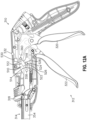
- FIGS. 11-12C show another illustrative surgical stapling instrument (310) that is generally similar to surgical stapling instrument (10) described above except as otherwise described below.
- Surgical stapling instrument (310) includes a handle assembly (312), a shaft assembly (314), and an end effector (e.g., 16) distally projecting from shaft assembly (314).
- Handle assembly (312) includes a saddle shaped slide (318), a closure trigger (320), and a firing trigger (322) in communication with end effector via shaft assembly (314).
- Translating slide (318) distally toward the end effector slides a retaining pin (e.g., 30) of the end effector distally (see e.g., FIG.
- Sequentially actuating closure trigger (320) and firing trigger (322) respectively compresses the tissue between the anvil and cartridge in a closed configuration and then forms a plurality of staples within the tissue and severs the tissue with a knife.
- a closure member (354) extends distally from handle assembly (312), through shaft assembly (314), and into end effector for operably coupling with the cartridge.
- a proximal end portion of closure member (354) is operatively coupled to closure trigger (320) by a sensing link (510) that is pivotally attached to the closure member (354) at opposite ends.
- sensing link (510) can serve as a clamp force sensor.
- closure trigger (320) is operable to be pivoted between a released position ( FIG. 12A ) and an actuated position ( FIG. 12B ) which can facilitate corresponding sliding of closure member (354) to facilitate selective clamping of tissue at the end effector, as described above.
- closure trigger (320) when closure trigger (320) is in the released position, the closure member (354) is in a retracted position which opens the cartridge relative to the anvil to allow for tissue to be provided therebetween.
- FIG. 12B when the closure trigger (320) is pivoted to the actuated position, the closure member is slid to a fully extended position which urges the cartridge towards the anvil to facilitate clamping of the tissue therebetween.
- Sensing link (510) is a spring actuated link and is configured to detect the force exerted between the closure trigger (320) and the closure member (354). As will be described in further detail below, this detected force can be a function of the clamping force exerted by the cartridge on tissue and can be used to determine whether tissue is improperly clamped to facilitate generation of a notification accordingly.
- sensing link (510) includes a support (512) and a plunger (514) that are slidable relative to each other and are biased apart by a spring (516).
- Support (512) includes a link pin (360) and a sleeve (518) that defines a receptacle (520).
- Plunger (514) includes a link pin (358) and a rod (522).
- Link pins (358, 360) operably couple sensing link (510) to closure member (354) and closure trigger (320).
- Spring (516) is disposed in receptacle (520) and rod (522) contacts spring (516) and extends partially into receptacle (520) to compress spring (516) within receptacle (520) such that spring (516) biases support (512) and plunger (514) apart.
- Rod (522) is slidable relative to sleeve (518) which allows sensing link (510) to be selectively compressed against the biasing of spring (516).
- Sensing link (510) further includes a switch assembly (524) that is selectively activated when support (512) and plunger (514) are compressed together beyond a predefined distance, as will be described in further detail below.
- Switch assembly (524) includes a switch (526) coupled with rod (522) and a pin (528) coupled with sleeve (518) and substantially aligned with switch (526). Sufficient compression of sensing link (510) can cause the pin (528) to depress switch (526) to facilitate activation thereof.
- sensing link (510) to clamping force applied to the tissue by the cartridge via closure trigger (320) can depend upon whether the tissue is properly clamped. For example, as illustrated in FIG. 12B , when the tissue is properly clamped, the clamping force applied to the tissue by closure trigger (320) and the cartridge is insufficient to overcome the biasing force of the spring (516) that is exerted on the rod (522) to prevent compression of sensing link (510). As a result, the sensing link remains substantially uncompressed such that the switch (526) remains open as an indication that the tissue is properly clamped. However, when the tissue is improperly clamped, as illustrated in FIG.
- the clamping force applied to the tissue by closure trigger (320) and the cartridge exceeds the biasing force of the spring (516) that is exerted on the rod (522) which causes the closure member (354) to be extended slightly rearwardly enough to compress the sensing link (510) and depress the switch (526) as an indication that the tissue is improperly clamped.
- a microprocessor (530) is communicatively coupled to switch (526) and a feedback generator (532).
- Microprocessor (530) may be embodied as any type of processor capable of performing the functions described herein.
- microprocessor (530) may be embodied as a single or multi-core processor, a digital signal processor, a microprocessor, a general purpose central processing unit (CPU), a reduced instruction set computer (RISC) processor, a processor having a pipeline, a complex instruction set computer (CISC) processor, an application specific integrated circuit (ASIC), a programmable logic device (PLD), a field programmable gate array (FPGA), or other processor or processing/controlling circuit or controller.
- CPU central processing unit
- RISC reduced instruction set computer
- CISC complex instruction set computer
- ASIC application specific integrated circuit
- PLD programmable logic device
- FPGA field programmable gate array
- Feedback generator (532) may be embodied as any type of generator processor capable of generating a notification, such as for example, a light, a speaker, a display, or some combination thereof.
- Switch (526), microprocessor (530), and feedback generator (532) can be powered from a remote power source connected to surgical stapling instrument (310) via a cable (not shown) or from an internal power source located onboard surgical stapling instrument (310), such as a battery, for example.
- Microprocessor (530) is configured to facilitate generation of an audible notification and/or a visual notification from feedback generator (532), as a function of the status of switch (526), to warn the user when the tissue is improperly clamped. For example, when the tissue is properly clamped, such that switch (526) is deactivated, the microprocessor (530) recognizes that the switch (526) is deactivated and provides a suitable notification via feedback generator (532) that indicates to a user that the tissue is properly clamped that the surgical stapling instrument (310) is ready to fire. In some examples, microprocessor (530) can deactivate the feedback generator (532) to provide such indication.
- microprocessor (530) can activate the feedback generator (532) to generate notification that is understood to indicate that the surgical stapling instrument (310) is ready to fire, such as a green light.
- the microprocessor (530) recognizes that the switch (526) is activated and can provide a suitable notification via feedback generator (532) that warns the user that the tissue is improperly clamped to prevent of the surgical stapling instrument (310).
- various characteristics of spring (516) such as spring constant, can be selected to achieve generation of the indication at a desired clamping force in order to accommodate a particular surgical setting.
- sensing link (510) can comprise any of a variety of suitable alternative sensors that facilitate detection of excessive clamping force, such as, for example, a Hall-effect sensor or an optical sensor.
- microprocessor (530) is configured to log certain information during the procedure in order to provide a historical record for the surgical stapling instrument (310) that can be accessed later to review the performance of the surgical stapling instrument (310).
- FIG. 13 shows an illustrative surgical stapling instrument (610) that is generally similar to surgical stapling instrument (310) described above except as otherwise described below.
- Surgical stapling instrument (310) includes a handle assembly (612), a shaft assembly (614), and an end effector (e.g., 16) distally projecting from shaft assembly (614).
- Handle assembly (612) includes a saddle shaped slide (618), a closure trigger (620), and a firing trigger (622) in communication with end effector via shaft assembly (614).
- a closure member (654) extends distally from handle assembly (612), through shaft assembly (614), and into end effector for operably coupling with the cartridge.
- a proximal end portion of closure member (654) is operatively coupled to closure trigger (620) by a sensing link (810) that is pivotally attached to the closure member (354) at opposite ends.
- Sensing link (810) includes a support (812), a plunger (814), and a switch assembly (824).
- Switch assembly (824) includes a switch (826) coupled with rod (822) and a pin (828) coupled with sleeve (818) and substantially aligned with switch (826).
- a microprocessor (830) is communicatively coupled to switch (826).
- Microprocessor (830) is communicatively coupled to a wireless communication module (836) that facilitates wireless communication with a console (not shown) via any of a variety of wireless communication protocols such as, for example, Wi-Fi, Cellular, or Wireless Personal Area Networks (WPAN) (e.g., IrDA, Bluetooth, Bluetooth Low Energy, Zigbee, wireless USB).
- WPAN Wireless Personal Area Networks
- Surgical stapler (610) may additionally or alternatively be configured to support wired communication via a communication port (not shown), such as a USB port, for example.
- the console (not shown) may receive a message from wireless communication module (836) and facilitates generation of a notification to a user of the surgical stapler (610).
- the console may include a data processor and a display that cooperate to generate the notification.
- the console may be a component of a robotic electrosurgical system.
- Switch (826), microprocessor (830), and wireless communication module (836) are powered by an onboard power source (838) which can comprise a disposable battery, a rechargeable battery, a supercapacitor or any of a variety of suitable alternative power storage arrangements.
- Microprocessor (830) is configured to monitor the status of switch (826) and to facilitate generation of an audible notification and/or a visual notification on the console, via wireless communication module (836), that warns the user that the tissue is improperly clamped to prevent them from firing the stapler. For example, when the tissue is improperly clamped such that switch (826) is activated, the microprocessor (830) recognizes the switch (826) as being activated and can transmit a message to the console, via wireless communication module (836), that causes the console to generate a notification that warns the user that tissue is improperly clamped to prevent them from firing provide the surgical stapler (610). The user can then reposition the stapler on tissue until proper clamping is achieved.
- microprocessor (830) can stop transmitting the message to terminate the notification on the console thus indicating to the user that surgical stapling instrument (610) is ready to fire.
- microprocessor (830) can instead transmit a different message to the console that causes the console to display a notification to the user indicating that surgical stapler (610) is ready to fire.
- the notification(s) presented by the console can be a visual notification, such as message displayed on a screen or a flashing light, an audible notification, such as a chime or a recorded spoken message, or a combination thereof.
- FIGS. 14 and 15 show an illustrative end effector (916) that is generally similar to end effector (16) described above except as otherwise described below.
- End effector (916) includes a cartridge (928) and a retainer pin (930).
- Cartridge (928) includes an anvil (926), a plurality of staples (not shown), a knife (e.g., 32) and a cartridge housing (1032) that is slidable with respect to anvil (932) between a clamped (closed) position and an unclamped (open) position in response to actuation of a closure trigger (e.g., 20, 320, 620) to facilitate clamping of tissue at end effector (916).
- End effector (916) includes a supporting structure (1028) that supports cartridge (928) and is attached to handle frame plates (935).
- a clamp force sensor (1210) is associated with the end effector (916) to facilitate detection of improper clamping of tissue between anvil (926) and cartridge housing (1032) as a function of deflection of the distal end of end effector (916).
- Clamp force sensor (1210) includes a microprocessor (1230), a wireless communication module (1236), an onboard power source (1238), and a sensing component, in the form of a strain gage (1240).
- Microprocessor (1230), wireless communication module (1236), and onboard power source (1238) are generally similar to microprocessor (830), wireless communication module (836), and onboard power source (838) described above except as otherwise described below.
- Strain gage (1240) is communicatively coupled to microprocessor (1230) via a wire (1242) and transmits deflection data to microprocessor (1230), as will be described in more detail below.
- Microprocessor (1230f) is communicatively coupled to wireless communication module (1236) to facilitate wireless communication with a remote console.
- Microprocessor (1230), wireless communication module (1236), onboard power source (1238), strain gage (1240) and wire (1242) are contained within a housing (1244) that is coupled with end effector (916).
- Microprocessor (1230), wireless communication module (1236), onboard power source (1238), and strain gage (1240) are arranged within housing (1244) such that microprocessor (1230), wireless communication module (1236), and onboard power source (1238), are disposed above cartridge housing (1032) and strain gage (1240) is disposed at a distal end of end effector (916) and adjacent to anvil (932).
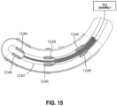
- Strain gage (1240) is configured to detect the deflection of anvil (932) that is indirectly imparted to the distal end of end effector (916). As illustrated in FIG. 15 , strain gage (1240) comprises a plurality of sensing pads (1246) that are distributed along the distal end of the end effector (916) and configured to detect deflection of anvil (932) as a function of the elongation of the sensing pads (1246) when anvil (932) is flexed. It is to be appreciated that strain gage (1240) can be any other configuration that facilitates measurement of deflection and can additionally or alternatively be mounted anywhere on end effector (916).
- the microprocessor (1230) is configured to detect improper clamping of the tissue as a function of the deflection of anvil (932) indirectly from deflection of the distal end of end effector (916).
- tissue is clamped between anvil (932) and cartridge housing (1032) (e.g., by closing closure trigger (20, 320, 620))
- the tissue may be too thick and/or improperly positioned between anvil (932) and cartridge housing (1032) to allow them to properly clamp together.
- Such improper clamping can cause excessive deflection of the anvil (932) and the distal end of the end effector (916).
- the microprocessor (1230) can therefore indirectly monitor the deflection of anvil (932) via strain gage (1240) to determine whether the tissue is improperly clamped and thus causing excessive deflection of anvil (932). If the microprocessor (1230) determines that anvil (932) is being excessively deflected by the tissue, microprocessor (1230) can transmit a message to the console, via wireless communication module (1236), that causes the console to generate a notification that warns the user that tissue is improperly clamped to prevent them from firing the stapler. The user can then reposition the stapler on the tissue until proper clamping is achieved.
- microprocessor (1230) can stop transmitting the message to terminate the notification on the console thus indicating to the user that surgical stapling instrument (e.g., 10, 310, 610) is ready to fire.
- microprocessor (1230) can transmit a different message to the console that causes the console to display a notification to the user indicating that surgical stapling instrument is ready to fire.
- the notification(s) presented by the console can be a visual notification, such as message displayed on a screen or a flashing light, an audible notification, such as a chime or a recorded spoken message, or a combination thereof.
- microprocessor (1230) can compare the deflection amount detected by strain gage (1240) to a threshold value to determine whether the tissue is improperly clamped.
- the threshold value can be understood to represent the minimum amount of deflection that the anvil (932) can undergo before cutting and/or stapling would be adversely affected. If the detected deflection is below the threshold value, thus indicating that the tissue is properly clamped, microprocessor (1230) refrains from transmitting a warning message to the console, or alternatively, transmits a permission message to the console to cause the console to notify the user that the surgical stapling instrument is ready to fire.
- microprocessor (1230) transmits the warning message to the console and the console, in response, notifies the user to refrain from firing the surgical stapling instrument before releasing the tissue and reclamping.
- strain gage (1240) and microprocessor (1230) can be selectively activated in response to clamping of the tissue in an effort to conserve power consumption. For example, prior to clamping of the tissue, such as when closure trigger (20, 320, 620) is opened, strain gage (1240) and microprocessor (1230) are deactivated (i.e., are in a sleep mode). Once the tissue is clamped between anvil (932) and cartridge housing (1032), strain gage (1240) and microprocessor (1230) can be activated to initialize sensing of the deflection of the anvil (932), as described above. The activation of strain gage (1240) and microprocessor (1230) can be a function of the position of the closure trigger.
- strain gage (1240) and microprocessor (1230) can be deactivated.
- the microprocessor can recognize the closing of the closure trigger and can initialize sensing of the deflection of the anvil (932) with strain gage (1240).
- microprocessor (1230) can recognize the status of the closure trigger via a switch (not shown) that is associated with the closure trigger and indicates whether the closure trigger is opened or closed.
- Anvil (932) might additionally or alternatively include a manual switch, such as a pushbutton or a microswitch that allows a user to manually control the activation of strain gage (1240) and microprocessor (1230) through activation of the switch.
- clamp force sensor (1210) is intended to be provided as a standalone device that can be incorporated onto a conventional end effector (e.g., 16) in order to add the sensing functionality described above to a surgical stapler instrument (e.g., 10).
- clamp force sensor (1210) can be provided as an aftermarket solution for adding the sensing functionality described above to an existing surgical stapling instrument, such as a surgical stapling instrument that has already been placed in service.
- clamp force sensor (1210) provides a cost effective and simple solution for providing the sensing functionality described above to a surgical stapling instrument that may not otherwise have such functionality.
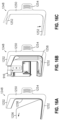
- FIGS. 16A-16C illustrate an applicator (1248) that can be provided as an accessory for clamp force sensor (1210) that facilitates installation of clamp force sensor (1210) onto end effector (916).
- applicator (1248) includes a central body (1250) and a pair of grasping features (1252) that extend from central body (1250) and are spaced from each other.
- a tab (1254) extends laterally from central body (1250).
- Central body (1250) and grasping features (1252) have an overall internal profile that generally conforms to an outer profile of housing (1244).
- clamp force sensor (1210) can be pressed into applicator (1248) such that grasping features (1252) initially spread apart to accept clamp force sensor (1210) and then are clamped over clamp force sensor (1210) to hold it in place once it is fully installed on applicator (1248), as illustrated in FIG. 16A .
- a protective layer (1256) is then removed from an adhesive strip (1258) that is routed along and adhered to an interior surface of clamp force sensor (1210) to expose an adhesive outer surface of adhesive strip (1258).
- clamp force sensor (1210) With protective layer (1256) removed, a user can push clamp force sensor (1210) into place over end effector (916) with enough force to properly adhere adhesive strip (1258) to end effector (916), as illustrated in FIG. 16B . With clamp force sensor (1210) adhered to end effector (916), applicator (1248) can then be removed from clamp force sensor (1210) by pulling grasp tab (1254) with enough force to cause grasping features (1252) to spread apart and disengage from clamp force sensor (1210).
- FIG. 17 shows an illustrative end effector (1316) that is generally similar to end effector (916) described above except as otherwise described below.
- End effector (1316) includes a cartridge (1328) and a retainer pin (1330).
- Cartridge (1328) includes an anvil (1326), a plurality of staples (not shown), a knife (e.g., 32) and a cartridge housing (1432) that is slidable with respect to anvil (1326) between a clamped (closed) position and an unclamped (open) position in response to actuation of a closure trigger (e.g., 20, 320, 620) to facilitate clamping of tissue at end effector (1316).
- End effector (1316) includes a supporting structure (1428) that supports cartridge (1328) and is attached to handle frame plates (1335).
- a clamp force sensor (1610) is incorporated into cartridge (1328) to facilitate detection of improper clamping of tissue between anvil (1326) and cartridge housing (1432).
- the clamp force sensor (1610) includes a microprocessor (1630), a wireless communication module (1636), an onboard power source (1638), and a sensing component, in the form of a strain gage (1640).
- Strain gage (1640) is communicatively coupled to microprocessor (1630) via a wire (1642).
- Microprocessor (1630) is communicatively coupled to wireless communication module (1636) to facilitate wireless communication with a remote console.
- Microprocessor (1630), wireless communication module (1636), and onboard power source (1638) are disposed within an interior chamber (1660) that is defined by cartridge housing (1432) such that microprocessor (1630), wireless communication module (1636), and onboard power source (1638) are disposed above cartridge housing (1432).
- Strain gage (1640) is configured to detect the deflection of anvil (1326) that occurs as a result of clamping tissue between anvil (1326) and cartridge housing (1432). As illustrated in FIG. 17 , strain gage (1640) is disposed within an interior chamber (1662) that is defined by anvil (1326) and extends along the anvil (1326) to facilitate detection of the deflection of anvil (1326) directly from anvil (1326).
- the microprocessor (1630) is configured to detect improper clamping of the tissue as a function of the deflection of anvil (1326) and facilitate generate of a notification on a remote console when the tissue is improperly clamped to prevent a user from firing the surgical stapler instrument.
- cartridge (1328) By integrating clamp force sensor (1610) into cartridge (1328), cartridge (1328) can be provided as a standalone device that can be incorporated onto a conventional end effector (e.g., 16) in order to add the sensing functionality described above to a surgical stapler instrument (e.g., 10). In some instances, cartridge (1328) can be provided as an aftermarket solution for adding the sensing functionality described above to an existing surgical stapling instrument, such as a surgical stapling instrument that has already been placed in service. As such, cartridge (1328) provides a cost effective and simple solution for providing the sensing functionality described above to a surgical stapling instrument that may not otherwise have such functionality.
- FIG. 18 shows an illustrative end effector (1716) that is generally similar to end effector (916) described above except as otherwise described below.
- End effector (1716) includes a cartridge (1728) and a retainer pin (1730).
- Cartridge (1728) includes an anvil (1726), a plurality of staples (not shown), a knife (e.g., 32) and a cartridge housing (1832) that is slidable with respect to anvil (1726) between a clamped (closed) position and an unclamped (open) position in response to actuation of a closure trigger (e.g., 20, 320, 620) to facilitate clamping of tissue at end effector (1716).
- End effector (1716) includes a supporting structure (1828) that supports cartridge (1728) and is attached to handle frame plates (1735).
- a clamp force sensor is incorporated into supporting structure (1828) of end effector (1716) to facilitate detection of improper clamping of tissue between anvil (1726) and cartridge housing (1832).
- the clamp force sensor includes a microprocessor (2030), a wireless communication module (2036), an onboard power source (2038), and a sensing component, in the form of a strain gage (2040). Strain gage (2040) is communicatively coupled to microprocessor (2030) via a wire (2042). Microprocessor (2030) is communicatively coupled to wireless communication module (2036) to facilitate wireless communication with a remote console.
- Microprocessor (2030), wireless communication module (2036), and onboard power source (2038) are disposed within an interior chamber (2060) that is defined by supporting structure (1828) such that microprocessor (2030), wireless communication module (2036), and onboard power source (2038) are disposed above cartridge housing (1832).
- Strain gage (2040) is configured to detect the deflection that occurs at the interface between anvil (1726) and the distal end of supporting structure (1828) as a result of clamping tissue between anvil (1326) and cartridge housing (1432). As illustrated in FIG. 17 , strain gage (2040) is provided at the interface between anvil (1726) and the extends along the anvil (1726) to facilitate detection of the deflection of anvil (1326) from beneath the anvil (1726).
- the microprocessor (2030) is configured to detect improper clamping of the tissue as a function of deflection beneath anvil (1726) and facilitate generate of a notification on a remote console when the tissue is improperly clamped to prevent a user from firing the surgical stapler instrument.
- FIG. 19 shows an illustrative end effector (2116) that is generally similar to end effector (916) described above except as otherwise described below.
- End effector (2116) includes a cartridge (2128) that includes an anvil (2126), a plurality of staples (not shown), a knife (e.g., 32) and a cartridge housing (2132) that is slidable with respect to anvil (2126) between a clamped (closed) position and an unclamped (open) position in response to actuation of a closure trigger (e.g., 20, 320, 620) to facilitate clamping of tissue at end effector (2116).
- End effector (2116) further includes a firing bar (e.g., 82) that interacts with cartridge (2128) to facilitate formation of staples (not shown) in the tissue and/or severing of the tissue with knife (e.g., 32).
- a firing bar e.g., 82
- a clamp force sensor (2410) is incorporated into cartridge (2128) to facilitate detection of improper clamping of tissue between anvil (1326) and cartridge housing (1432).
- the clamp force sensor (2410) includes a microprocessor (2430), a wireless communication module (2436), an onboard power source (2438), and a sensing component, in the form of a strain gage (2440). Strain gage (2440) is incorporated between the firing bar and the knife and is configured to facilitate detection of the distance and clamping force between anvil (2126) and cartridge housing (2132) during firing of the surgical stapling instrument.
- FIGS. 20-22 shows an illustrative supporting structure (2628) for an end effector (e.g., 16, 616, 916) that is generally similar to supporting structures (128, 1028, 1428) described above except as otherwise described below.
- Supporting structure (2628) includes an intelligent cuff (2860) that is configured for installation over a distal end of supporting structure (2628), as illustrated in FIGS. 20 and 21 .
- Cuff (2860) includes a strain gage (not shown) that facilitates detection of a clamping force at the distal end of supporting structure (2628).
- Cuff (2860) is communicatively coupled with a microprocessor (not shown) and a wireless communication module (not shown) that cooperate to provide clamping force feedback to a user in a similar manner as described above.
- a microprocessor not shown
- a wireless communication module not shown
- an anvil 2526
- cuff 2860
- An apparatus comprises (a) a handle assembly comprising a closure trigger that is pivotable between a released position and an actuated position; (b) a shaft assembly; (c) an end effector coupled with the shaft assembly and comprising a cartridge that includes an anvil and a cartridge housing, the cartridge housing being slidable with respect to the anvil between an unclamped position and a clamped position to facilitate selective clamping of patient tissue therebetween; and (d) a clamp force sensor associated with the end effector and configured to detect a clamping force between the anvil and the cartridge housing and facilitate generation of a notification as a function of the detected clamping force.
- the clamp force sensor comprises a sensing component, a controller in signal communication with the sensing component, a communication module that facilitates communication with a remote computing device, and a power module that facilitates powering of the clamp force sensor.
- Example 2 wherein: (a) the end effector further comprises a supporting structure configured to facilitate selective retention of the cartridge, (b)the clamp force sensor is coupled with the supporting structure such that the sensing component is located at a distal end of the end effector adjacent to the anvil, and (c) the controller, the communication module, and the power module are located at a proximal end of the end effector adjacent the cartridge housing.
- Example 3 wherein the sensing component, the controller, the communication module, and the power module are disposed within a housing that is releasably coupled to the supporting structure.
- Example 4 The apparatus of Example 4, wherein the housing is releasably coupled to the supporting structure with adhesive.
- Example 5 in combination with an applicator that is configured for releasably grasping the housing to facilitate selective installation of the housing onto the support structure.
- the sensing component comprises a strain gage
- the power module comprises a battery
- the communication module comprises a wireless communication module that facilitates wireless communication with the remote computing device.
- Example 8 wherein (i) the sensing component is located at a distal end of the end effector adjacent to the anvil and the controller, (ii) the communication module, and the power module are located at a proximal end of the end effector adjacent the cartridge housing, and (iii) the sensing component is coupled with communication module with a wire that extends therebetween and is disposed in the interior chamber.
- the sensing component comprises a strain gage
- the power module comprises a battery
- the communication module comprises a wireless communication module that facilitates wireless communication with the remote computing device.
- Example 11 The apparatus of Example 11, wherein (i) the cartridge housing defines a first interior chamber, and (ii) the controller, the communication module, and the power module are disposed within the first interior chamber.
- Example 12 The apparatus of Example 12, wherein the sensing component is coupled with the anvil.
- Example 13 The apparatus of Example 13, wherein (i) the anvil defines a second interior chamber, (ii) the sensing component is disposed within the first interior chamber, and (iii) the sensing component is coupled with communication module with a wire that extends between the first interior chamber and the second interior chamber.
- the sensing component comprises a strain gage
- the power module comprises a battery
- the communication module comprises a wireless communication module that facilitates wireless communication with the remote computing device.
- An apparatus comprises (a) a handle assembly comprising a closure trigger that is pivotable between a released position and an actuated position; (b) a shaft assembly; (c) an end effector coupled with the shaft assembly and comprising an anvil and a cartridge housing, the cartridge housing being slidable with respect to the anvil between an unclamped position and a clamped position to facilitate selective clamping of patient tissue therebetween and (d) a clamp force sensing link operably coupled with the shaft assembly and the closure trigger such that pivoting of the closure trigger from the released position to the actuated position facilitates actuation of the end effector from the unclamped position to the clamped position via the clamp force sensing link and the shaft assembly, wherein the clamp force sensing link is configured to detect a force exerted by the closure trigger on the end effector to facilitate generation of a notification as a function of the detected force.
- Example 16 wherein the clamp force sensing link is configured to facilitate generation of an alarm when the detected force exceeds a threshold value.
- clamp force sensing link comprises: (i) a rod and a sleeve coupled with opposing ones of the closure trigger and the shaft assembly; (ii) a spring that biases the rod and sleeve apart; and (iii) a switch assembly that is selectively activated when the rod and the sleeve are compressed together beyond a predefined distance.
- a cartridge for a surgical stapler comprises (a) an anvil; (b) a cartridge housing that is slidable with respect to the anvil between an unclamped position and a clamped position to facilitate selective clamping of patient tissue between the anvil and the cartridge housing; and (c) a clamp force sensor comprising a sensing component, a controller in signal communication with the sensing component, a communication module that facilitates communication with a remote computing device, and a power module that facilitates powering of the clamp force sensor, wherein the clamp force sensor is configured to detect a clamping force between the anvil and the cartridge housing and facilitate generation of a notification as a function of the detected clamping force.
- an end effector in accordance with various embodiments can comprise electrodes configured to heat and seal the tissue.
- an end effector in accordance with certain embodiments can apply vibrational energy to seal the tissue.
- Versions of the devices described above may be designed to be disposed of after a single use, or they can be designed to be used multiple times. Versions may, in either or both cases, be reconditioned for reuse after at least one use. Reconditioning may include any combination of the steps of disassembly of the device, followed by cleaning or replacement of particular pieces, and subsequent reassembly. In particular, some versions of the device may be disassembled, and any number of the particular pieces or parts of the device may be selectively replaced or removed in any combination. Upon cleaning and/or replacement of particular parts, some versions of the device may be reassembled for subsequent use either at a reconditioning facility, or by an operator immediately prior to a procedure.
- reconditioning of a device may utilize a variety of techniques for disassembly, cleaning/replacement, and reassembly. Use of such techniques, and the resulting reconditioned device, are all within the scope of the present application.
- versions described herein may be sterilized before and/or after a procedure.
- the device is placed in a closed and sealed container, such as a plastic or TYVEK bag.
- the container and device may then be placed in a field of radiation that can penetrate the container, such as gamma radiation, x-rays, or high-energy electrons.
- the radiation may kill bacteria on the device and in the container.
- the sterilized device may then be stored in the sterile container for later use.
- a device may also be sterilized using any other technique known in the art, including but not limited to beta or gamma radiation, ethylene oxide, or steam.
Landscapes
- Health & Medical Sciences (AREA)
- Life Sciences & Earth Sciences (AREA)
- Surgery (AREA)
- Heart & Thoracic Surgery (AREA)
- Engineering & Computer Science (AREA)
- Biomedical Technology (AREA)
- Nuclear Medicine, Radiotherapy & Molecular Imaging (AREA)
- Medical Informatics (AREA)
- Molecular Biology (AREA)
- Animal Behavior & Ethology (AREA)
- General Health & Medical Sciences (AREA)
- Public Health (AREA)
- Veterinary Medicine (AREA)
- Surgical Instruments (AREA)
Applications Claiming Priority (1)
| Application Number | Priority Date | Filing Date | Title |
|---|---|---|---|
| US18/502,500 US12390219B2 (en) | 2023-11-06 | 2023-11-06 | Surgical stapler with clamp force sensor |
Publications (1)
| Publication Number | Publication Date |
|---|---|
| EP4548862A1 true EP4548862A1 (de) | 2025-05-07 |
Family
ID=93333867
Family Applications (1)
| Application Number | Title | Priority Date | Filing Date |
|---|---|---|---|
| EP24209400.1A Pending EP4548862A1 (de) | 2023-11-06 | 2024-10-29 | Chirurgisches klammergerät mit klemmkraftsensor |
Country Status (3)
| Country | Link |
|---|---|
| US (1) | US12390219B2 (de) |
| EP (1) | EP4548862A1 (de) |
| CN (1) | CN119924926A (de) |
Citations (16)
| Publication number | Priority date | Publication date | Assignee | Title |
|---|---|---|---|---|
| US20050131390A1 (en) * | 2002-04-25 | 2005-06-16 | Russell Heinrich | Surgical instruments including mems devices |
| US20050139636A1 (en) | 2003-12-30 | 2005-06-30 | Schwemberger Richard F. | Replaceable cartridge module for a surgical stapling and cutting instrument |
| US20050143759A1 (en) | 2003-12-30 | 2005-06-30 | Kelly William D. | Curved cutter stapler shaped for male pelvis |
| US20050145672A1 (en) | 2003-12-30 | 2005-07-07 | Schwemberger Richard F. | Curved cutter stapler with aligned tissue retention feature |
| US6988650B2 (en) | 2003-12-30 | 2006-01-24 | Ethicon Endo-Surgery, Inc. | Retaining pin lever advancement mechanism for a curved cutter stapler |
| US7134587B2 (en) | 2003-12-30 | 2006-11-14 | Ethicon Endo-Surgery, Inc. | Knife retraction arm for a curved cutter stapler |
| US20060273135A1 (en) * | 2005-06-03 | 2006-12-07 | Beetel Robert J | Surgical instruments employing sensors |
| US7147139B2 (en) | 2003-12-30 | 2006-12-12 | Ethicon Endo-Surgery, Inc | Closure plate lockout for a curved cutter stapler |
| US7147140B2 (en) | 2003-12-30 | 2006-12-12 | Ethicon Endo - Surgery, Inc. | Cartridge retainer for a curved cutter stapler |
| US7204404B2 (en) | 2003-12-30 | 2007-04-17 | Ethicon Endo-Surgery, Inc. | Slotted pins guiding knife in a curved cutter stapler |
| US7207472B2 (en) | 2003-12-30 | 2007-04-24 | Ethicon Endo-Surgery, Inc. | Cartridge with locking knife for a curved cutter stapler |
| US20150122871A1 (en) * | 2009-08-11 | 2015-05-07 | Covidien Lp | Surgical stapling apparatus |
| US20170189022A1 (en) * | 2015-12-31 | 2017-07-06 | Ethicon Endo-Surgery, Llc | Method of applying staples in lower anterior bowel resection |
| US10194913B2 (en) | 2015-07-30 | 2019-02-05 | Ethicon Llc | Surgical instrument comprising systems for assuring the proper sequential operation of the surgical instrument |
| US20220104822A1 (en) * | 2020-10-02 | 2022-04-07 | Ethicon Llc | Method for operating tiered operation modes in a surgical system |
| US20230007859A1 (en) | 2021-07-09 | 2023-01-12 | Cilag Gmbh International | Cartridge retention features for curved surgical stapler |
Family Cites Families (9)
| Publication number | Priority date | Publication date | Assignee | Title |
|---|---|---|---|---|
| US7845537B2 (en) * | 2006-01-31 | 2010-12-07 | Ethicon Endo-Surgery, Inc. | Surgical instrument having recording capabilities |
| US11857181B2 (en) * | 2007-06-04 | 2024-01-02 | Cilag Gmbh International | Robotically-controlled shaft based rotary drive systems for surgical instruments |
| US8276801B2 (en) * | 2011-02-01 | 2012-10-02 | Tyco Healthcare Group Lp | Surgical stapling apparatus |
| US10478182B2 (en) * | 2012-10-18 | 2019-11-19 | Covidien Lp | Surgical device identification |
| US20180256161A1 (en) * | 2017-03-08 | 2018-09-13 | Covidien Lp | Surgical instruments including sensors |
| US10918310B2 (en) * | 2018-01-03 | 2021-02-16 | Biosense Webster (Israel) Ltd. | Fast anatomical mapping (FAM) using volume filling |
| US11969142B2 (en) * | 2017-12-28 | 2024-04-30 | Cilag Gmbh International | Method of compressing tissue within a stapling device and simultaneously displaying the location of the tissue within the jaws |
| US12016557B2 (en) * | 2020-06-10 | 2024-06-25 | Covidien Lp | Sealed electrical connection between surgical loading unit and adapter |
| US20220346781A1 (en) * | 2021-04-30 | 2022-11-03 | Cilag Gmbh International | Staple cartridge comprising staple drivers and stability supports |
-
2023
- 2023-11-06 US US18/502,500 patent/US12390219B2/en active Active
-
2024
- 2024-10-29 EP EP24209400.1A patent/EP4548862A1/de active Pending
- 2024-11-06 CN CN202411574360.2A patent/CN119924926A/zh active Pending
Patent Citations (17)
| Publication number | Priority date | Publication date | Assignee | Title |
|---|---|---|---|---|
| US20050131390A1 (en) * | 2002-04-25 | 2005-06-16 | Russell Heinrich | Surgical instruments including mems devices |
| US7147140B2 (en) | 2003-12-30 | 2006-12-12 | Ethicon Endo - Surgery, Inc. | Cartridge retainer for a curved cutter stapler |
| US7207472B2 (en) | 2003-12-30 | 2007-04-24 | Ethicon Endo-Surgery, Inc. | Cartridge with locking knife for a curved cutter stapler |
| US20050145672A1 (en) | 2003-12-30 | 2005-07-07 | Schwemberger Richard F. | Curved cutter stapler with aligned tissue retention feature |
| US6988650B2 (en) | 2003-12-30 | 2006-01-24 | Ethicon Endo-Surgery, Inc. | Retaining pin lever advancement mechanism for a curved cutter stapler |
| US7134587B2 (en) | 2003-12-30 | 2006-11-14 | Ethicon Endo-Surgery, Inc. | Knife retraction arm for a curved cutter stapler |
| US20050139636A1 (en) | 2003-12-30 | 2005-06-30 | Schwemberger Richard F. | Replaceable cartridge module for a surgical stapling and cutting instrument |
| US20050143759A1 (en) | 2003-12-30 | 2005-06-30 | Kelly William D. | Curved cutter stapler shaped for male pelvis |
| US7147139B2 (en) | 2003-12-30 | 2006-12-12 | Ethicon Endo-Surgery, Inc | Closure plate lockout for a curved cutter stapler |
| US7204404B2 (en) | 2003-12-30 | 2007-04-17 | Ethicon Endo-Surgery, Inc. | Slotted pins guiding knife in a curved cutter stapler |
| US20060273135A1 (en) * | 2005-06-03 | 2006-12-07 | Beetel Robert J | Surgical instruments employing sensors |
| US20150122871A1 (en) * | 2009-08-11 | 2015-05-07 | Covidien Lp | Surgical stapling apparatus |
| US10194913B2 (en) | 2015-07-30 | 2019-02-05 | Ethicon Llc | Surgical instrument comprising systems for assuring the proper sequential operation of the surgical instrument |
| US20170189022A1 (en) * | 2015-12-31 | 2017-07-06 | Ethicon Endo-Surgery, Llc | Method of applying staples in lower anterior bowel resection |
| US10045780B2 (en) | 2015-12-31 | 2018-08-14 | Ethicon Llc | Method of applying staples in lower anterior bowel resection |
| US20220104822A1 (en) * | 2020-10-02 | 2022-04-07 | Ethicon Llc | Method for operating tiered operation modes in a surgical system |
| US20230007859A1 (en) | 2021-07-09 | 2023-01-12 | Cilag Gmbh International | Cartridge retention features for curved surgical stapler |
Also Published As
| Publication number | Publication date |
|---|---|
| US12390219B2 (en) | 2025-08-19 |
| US20250143697A1 (en) | 2025-05-08 |
| CN119924926A (zh) | 2025-05-06 |
Similar Documents
| Publication | Publication Date | Title |
|---|---|---|
| EP3673824B1 (de) | Chirurgisches klammergerät mit gewebeeingriffsmerkmalen um einen gewebehaltestift | |
| EP3187127B1 (de) | Chirurgisches klammergerät mit einer hubendanzeige | |
| US10973521B2 (en) | Surgical stapler with variable height drivers for uniform staple formation | |
| US11497493B2 (en) | Surgical stapler with fixed jaw support pin | |
| US10610219B2 (en) | Surgical stapler with curved outer surface on anvil | |
| CN113727662B (zh) | 用于直角外科缝合器的组织切割垫圈 | |
| EP3673826A1 (de) | Chirurgisches klammergerät mit geneigtem stapeldeck für variable gewebekompression | |
| EP2130500B1 (de) | Messer-/Betätigungsstangenverbindung für ein chirurgisches Instrument | |
| EP3730070B1 (de) | Kassettenbasierter sperrmechanismus für rechtwinklige chirurgische klammergeräte | |
| EP2130499A1 (de) | Mechanisch schwenkbarer Kartuschenkanal für chirurgisches Instrument | |
| US20170189021A1 (en) | Surgical stapler with locking translatable pin | |
| EP4548862A1 (de) | Chirurgisches klammergerät mit klemmkraftsensor |
Legal Events
| Date | Code | Title | Description |
|---|---|---|---|
| PUAI | Public reference made under article 153(3) epc to a published international application that has entered the european phase |
Free format text: ORIGINAL CODE: 0009012 |
|
| STAA | Information on the status of an ep patent application or granted ep patent |
Free format text: STATUS: THE APPLICATION HAS BEEN PUBLISHED |
|
| AK | Designated contracting states |
Kind code of ref document: A1 Designated state(s): AL AT BE BG CH CY CZ DE DK EE ES FI FR GB GR HR HU IE IS IT LI LT LU LV MC ME MK MT NL NO PL PT RO RS SE SI SK SM TR |
|
| STAA | Information on the status of an ep patent application or granted ep patent |
Free format text: STATUS: REQUEST FOR EXAMINATION WAS MADE |
|
| 17P | Request for examination filed |
Effective date: 20251106 |
|
| GRAP | Despatch of communication of intention to grant a patent |
Free format text: ORIGINAL CODE: EPIDOSNIGR1 |
|
| STAA | Information on the status of an ep patent application or granted ep patent |
Free format text: STATUS: GRANT OF PATENT IS INTENDED |
|
| INTG | Intention to grant announced |
Effective date: 20260303 |