EP4549012A1 - Réacteur à plasma pour traitement de gaz - Google Patents
Réacteur à plasma pour traitement de gaz Download PDFInfo
- Publication number
- EP4549012A1 EP4549012A1 EP23207300.7A EP23207300A EP4549012A1 EP 4549012 A1 EP4549012 A1 EP 4549012A1 EP 23207300 A EP23207300 A EP 23207300A EP 4549012 A1 EP4549012 A1 EP 4549012A1
- Authority
- EP
- European Patent Office
- Prior art keywords
- electrodes
- electrode
- plasma reactor
- plasma
- passage
- Prior art date
- Legal status (The legal status is an assumption and is not a legal conclusion. Google has not performed a legal analysis and makes no representation as to the accuracy of the status listed.)
- Withdrawn
Links
Images




Classifications
-
- B—PERFORMING OPERATIONS; TRANSPORTING
- B01—PHYSICAL OR CHEMICAL PROCESSES OR APPARATUS IN GENERAL
- B01J—CHEMICAL OR PHYSICAL PROCESSES, e.g. CATALYSIS OR COLLOID CHEMISTRY; THEIR RELEVANT APPARATUS
- B01J19/00—Chemical, physical or physico-chemical processes in general; Their relevant apparatus
- B01J19/08—Processes employing the direct application of electric or wave energy, or particle radiation; Apparatus therefor
- B01J19/087—Processes employing the direct application of electric or wave energy, or particle radiation; Apparatus therefor employing electric or magnetic energy
- B01J19/088—Processes employing the direct application of electric or wave energy, or particle radiation; Apparatus therefor employing electric or magnetic energy giving rise to electric discharges
-
- B—PERFORMING OPERATIONS; TRANSPORTING
- B01—PHYSICAL OR CHEMICAL PROCESSES OR APPARATUS IN GENERAL
- B01J—CHEMICAL OR PHYSICAL PROCESSES, e.g. CATALYSIS OR COLLOID CHEMISTRY; THEIR RELEVANT APPARATUS
- B01J2219/00—Chemical, physical or physico-chemical processes in general; Their relevant apparatus
- B01J2219/08—Processes employing the direct application of electric or wave energy, or particle radiation; Apparatus therefor
- B01J2219/0801—Controlling the process
-
- B—PERFORMING OPERATIONS; TRANSPORTING
- B01—PHYSICAL OR CHEMICAL PROCESSES OR APPARATUS IN GENERAL
- B01J—CHEMICAL OR PHYSICAL PROCESSES, e.g. CATALYSIS OR COLLOID CHEMISTRY; THEIR RELEVANT APPARATUS
- B01J2219/00—Chemical, physical or physico-chemical processes in general; Their relevant apparatus
- B01J2219/08—Processes employing the direct application of electric or wave energy, or particle radiation; Apparatus therefor
- B01J2219/0803—Processes employing the direct application of electric or wave energy, or particle radiation; Apparatus therefor employing electric or magnetic energy
- B01J2219/0805—Processes employing the direct application of electric or wave energy, or particle radiation; Apparatus therefor employing electric or magnetic energy giving rise to electric discharges
- B01J2219/0807—Processes employing the direct application of electric or wave energy, or particle radiation; Apparatus therefor employing electric or magnetic energy giving rise to electric discharges involving electrodes
- B01J2219/0809—Processes employing the direct application of electric or wave energy, or particle radiation; Apparatus therefor employing electric or magnetic energy giving rise to electric discharges involving electrodes employing two or more electrodes
- B01J2219/0813—Processes employing the direct application of electric or wave energy, or particle radiation; Apparatus therefor employing electric or magnetic energy giving rise to electric discharges involving electrodes employing two or more electrodes employing four electrodes
-
- B—PERFORMING OPERATIONS; TRANSPORTING
- B01—PHYSICAL OR CHEMICAL PROCESSES OR APPARATUS IN GENERAL
- B01J—CHEMICAL OR PHYSICAL PROCESSES, e.g. CATALYSIS OR COLLOID CHEMISTRY; THEIR RELEVANT APPARATUS
- B01J2219/00—Chemical, physical or physico-chemical processes in general; Their relevant apparatus
- B01J2219/08—Processes employing the direct application of electric or wave energy, or particle radiation; Apparatus therefor
- B01J2219/0803—Processes employing the direct application of electric or wave energy, or particle radiation; Apparatus therefor employing electric or magnetic energy
- B01J2219/0805—Processes employing the direct application of electric or wave energy, or particle radiation; Apparatus therefor employing electric or magnetic energy giving rise to electric discharges
- B01J2219/0807—Processes employing the direct application of electric or wave energy, or particle radiation; Apparatus therefor employing electric or magnetic energy giving rise to electric discharges involving electrodes
- B01J2219/0822—The electrode being consumed
-
- B—PERFORMING OPERATIONS; TRANSPORTING
- B01—PHYSICAL OR CHEMICAL PROCESSES OR APPARATUS IN GENERAL
- B01J—CHEMICAL OR PHYSICAL PROCESSES, e.g. CATALYSIS OR COLLOID CHEMISTRY; THEIR RELEVANT APPARATUS
- B01J2219/00—Chemical, physical or physico-chemical processes in general; Their relevant apparatus
- B01J2219/08—Processes employing the direct application of electric or wave energy, or particle radiation; Apparatus therefor
- B01J2219/0803—Processes employing the direct application of electric or wave energy, or particle radiation; Apparatus therefor employing electric or magnetic energy
- B01J2219/0805—Processes employing the direct application of electric or wave energy, or particle radiation; Apparatus therefor employing electric or magnetic energy giving rise to electric discharges
- B01J2219/0807—Processes employing the direct application of electric or wave energy, or particle radiation; Apparatus therefor employing electric or magnetic energy giving rise to electric discharges involving electrodes
- B01J2219/0824—Details relating to the shape of the electrodes
- B01J2219/0826—Details relating to the shape of the electrodes essentially linear
- B01J2219/083—Details relating to the shape of the electrodes essentially linear cylindrical
-
- B—PERFORMING OPERATIONS; TRANSPORTING
- B01—PHYSICAL OR CHEMICAL PROCESSES OR APPARATUS IN GENERAL
- B01J—CHEMICAL OR PHYSICAL PROCESSES, e.g. CATALYSIS OR COLLOID CHEMISTRY; THEIR RELEVANT APPARATUS
- B01J2219/00—Chemical, physical or physico-chemical processes in general; Their relevant apparatus
- B01J2219/08—Processes employing the direct application of electric or wave energy, or particle radiation; Apparatus therefor
- B01J2219/0803—Processes employing the direct application of electric or wave energy, or particle radiation; Apparatus therefor employing electric or magnetic energy
- B01J2219/0805—Processes employing the direct application of electric or wave energy, or particle radiation; Apparatus therefor employing electric or magnetic energy giving rise to electric discharges
- B01J2219/0807—Processes employing the direct application of electric or wave energy, or particle radiation; Apparatus therefor employing electric or magnetic energy giving rise to electric discharges involving electrodes
- B01J2219/0837—Details relating to the material of the electrodes
- B01J2219/0839—Carbon
-
- B—PERFORMING OPERATIONS; TRANSPORTING
- B01—PHYSICAL OR CHEMICAL PROCESSES OR APPARATUS IN GENERAL
- B01J—CHEMICAL OR PHYSICAL PROCESSES, e.g. CATALYSIS OR COLLOID CHEMISTRY; THEIR RELEVANT APPARATUS
- B01J2219/00—Chemical, physical or physico-chemical processes in general; Their relevant apparatus
- B01J2219/08—Processes employing the direct application of electric or wave energy, or particle radiation; Apparatus therefor
- B01J2219/0803—Processes employing the direct application of electric or wave energy, or particle radiation; Apparatus therefor employing electric or magnetic energy
- B01J2219/0805—Processes employing the direct application of electric or wave energy, or particle radiation; Apparatus therefor employing electric or magnetic energy giving rise to electric discharges
- B01J2219/0807—Processes employing the direct application of electric or wave energy, or particle radiation; Apparatus therefor employing electric or magnetic energy giving rise to electric discharges involving electrodes
- B01J2219/0837—Details relating to the material of the electrodes
- B01J2219/0841—Metal
-
- B—PERFORMING OPERATIONS; TRANSPORTING
- B01—PHYSICAL OR CHEMICAL PROCESSES OR APPARATUS IN GENERAL
- B01J—CHEMICAL OR PHYSICAL PROCESSES, e.g. CATALYSIS OR COLLOID CHEMISTRY; THEIR RELEVANT APPARATUS
- B01J2219/00—Chemical, physical or physico-chemical processes in general; Their relevant apparatus
- B01J2219/08—Processes employing the direct application of electric or wave energy, or particle radiation; Apparatus therefor
- B01J2219/0869—Feeding or evacuating the reactor
-
- B—PERFORMING OPERATIONS; TRANSPORTING
- B01—PHYSICAL OR CHEMICAL PROCESSES OR APPARATUS IN GENERAL
- B01J—CHEMICAL OR PHYSICAL PROCESSES, e.g. CATALYSIS OR COLLOID CHEMISTRY; THEIR RELEVANT APPARATUS
- B01J2219/00—Chemical, physical or physico-chemical processes in general; Their relevant apparatus
- B01J2219/08—Processes employing the direct application of electric or wave energy, or particle radiation; Apparatus therefor
- B01J2219/0873—Materials to be treated
- B01J2219/0875—Gas
Definitions
- Plasma reactors for gas conversion are known in the art. A number of different classes/types can be discerned. Dielectric Barrier Discharges (DBD) and Nanosecond Pulsed Discharges (NPD) can be classified as part of the so-called cold discharge reactors in which plasma is generally operated at temperatures from close to room temperature up to temperatures of about 1000K.
- the chemical gas conversion in cold plasma reactors is mainly based on electron-impact dissociation forming plasma activated species such as radicals, ions and energy excited atoms and molecules.
- the reactors provide comparatively limited profit from thermal dissociation. Short residence times at high temperature may be locally reached inside discharge channels. However, a part of the gas flow will inevitably not be directly exposed to the discharge channels causing an overall low conversion in practice.
- each module limited in its output power potential.
- Their frequency of operation is 1-1000 kHz but not less than the gliding arc (re-ignition) frequency.
- Known GAD type reactors including the rotating vortex variations, remain susceptible to variations in arc stability and/or local temperature variations. Specifically, effects like arc merging/splitting, can negatively affect a gas flow's apparent residence time and/or exposure to plasma and/or heat.
- pulsed arc discharges in two-electrode configurations is known from the field.
- Various parameters determine the average energy density of treated gases including: the energy per pulse, the pulse frequency (or repetition rate), gas composition and flow.
- Pulse lengths typically may vary from the nanosecond to millisecond time scale.
- CA2660088 discloses a plasma reactor configured for generating cold plasma pulses simultaneously between a plurality of electrodes and a common counter electrode (as opposed to a single arc interconnecting an electrode pair).
- the cold arc discharges are generated using either a plurality of HV electrodes in combination with a single ground electrode or a single HV electrode in combination with a plurality of ground electrodes.
- the present invention aims to provide a reactor for plasma conversion capable of sustaining more stable and/or uniform plasma exposure to a flow of reagent(s).
- the reactor comprises a passage that is provided within an interior volume of a reactor housing.
- the passage has a throat area that is fluidly connected to a reactor outlet.
- the reactor comprises at least two pairs of electrodes.
- the electrodes are also referred to as high voltage (HV) electrodes.
- Each electrode comprises: an electrode tube, referenced to as tubular jacket; an electrode rod extending longitudinally within the jacket; and a first inlet for injecting a flow of a primary fluid flow along a surface of the electrode rod towards a tip of the respective electrode rod.
- HV electrode rods it can be preferred to guide HV electrode rods through the tubes leaving only a narrow space between the outer surface of HV electrodes and the inner surface of electrode tubes. In this manner, high flow velocities are obtained which will be effective for cooling the HV electrode rods.
- Conductive heat transport via electrodes is effectively used for pre-heating primary gas, thus avoiding thermal conduction heat losses.
- the electrode rods are distributed, pair wise, around a longitudinal axis of the passage whereby the tips of the electrode rods are positioned upstream the throat area.
- the tips of the electrode rods are preferably about equidistantly separated from the throat.
- the reactor includes a second inlet for injecting a secondary gas, said second inlet being positioned upstream or downstream the throat area.
- the secondary gas is injected between the electrode tips and directed towards the throat of the passage. Alternatively, it may be brought in contact with the generated plasma at a lower point downstream.
- the reactor may include multiple inlets for secondary gas reagents. Secondary inlets preferably open along an axis centrally between the electrode tips.
- An electric operating circuit is connected to the electrodes and comprises at least one power source.
- the power source is driven to repetitively and simultaneously power electrode pairs at a voltage and rate generating arc discharges bridging the electrodes of each electrode pair, and to drive neighboring electrodes of adjacent pairs synchronously at the same time-varying potential.
- each of the electrodes is galvanically decoupled from the driving circuit, specifically the power source and the remaining HV electrodes in the system. Decoupling can be provided by a current limiting element as known in the field, typically a capacitor.
- arc merging/splitting can be mitigated or essentially eliminated by: separately galvanic decoupling.
- each electrode capacitively or inductively to the circuit.
- the electrodes can be coupled to a separate power supply.
- the reactor can advantageously generate multiple pulsed arc discharges in a primary plasma gas flow, within a converging flow plasma reactor.
- a secondary gas flow can be mixed inside the converging flow reactor volume with the downstream primary gas plasma.
- the generated pulsed arc discharges can be generally V-shape structured, extend towards the throat area of the passage, getting close to each other while remaining separated.
- the separate capacitive coupling of the electrodes to a single power source can be realized by isolating each of the electrodes from the circuits by a capacitor, or for example a series of capacitators.
- the isolation may be provided by wiring via a transmission line capacitor (e.g. coaxial cable).
- the capacitance of the capacitors is preferably within a comparatively limited tolerance range. Most preferably all capacitors are approximately equal, or at least within 5%, most preferably within 1%.
- plasma-activated primary gas flows (from the electrodes) react with the secondary gas.
- the arc discharges can advantageously extend towards the mixed zone of primary and secondary gas. Accordingly, the chemical conversion reaction of the primary and secondary gas mixture principally occurs in a limited volume inside or nearby the throat area.
- the passage comprises a nozzle converging towards the reactor outlet, wherein said throat area is provided in said nozzle.
- the limited volume, together with accelerated flow velocities resulting from the converging nozzle, allow for short gas residence times within this volume. Residence times can advantageously be in the sub-millisecond range. Depending on the geometry, dissipated electrical power and flow settings, residence times of the order of 0.1 ms can be reached.
- Multiple gas flow paths through the constricted volume wherein multiple, uniformly distributed, synchronized, proximate non-merging arc discharges are generated, advantageously provide one or more of: comparatively high uniformity of the temperature and plasma species concentration profiles within separated gas flow paths through the nozzle as a function of time; sub-millisecond average residence times; and limited spreading of the residence times.
- observed realizing of separated arcs is believed to be at least in part facilitated by an outwardly projected portion of momentary unipolar charged flow of the first gas from the tip of each electrode.
- the spacing between adjacent ones of the electrode tips may be about equal.
- the tips are distributed about homogenously around a circular trajectory upstream the throat area.
- electrode rods can be arranged in pairs of linear rows at approximately equal distance from each other within a row and at approximately equal distance from the throat area of the passage.
- the spacing between tips and the angle between adjacent electrode rods depends on a number n of arc-generating electrode pairs (n ⁇ 2) provided.
- arc-generating electrode pairs can be arranged around a circular trajectory or along a linear row upstream the throat area with a first spacing between electrode tips within each pair, operated at different time-varying potential and a second spacing between electrode tips from adjacent pairs, operated at the same and synchronized time-varying potential.
- the second spacing between electrodes of adjacent pairs, operated at the same time-varying potential can be made relatively small with respect to the first spacing within pairs. This results in a more uniform plasma treatment of the primary gas flow.
- Positioning the tips of rods that, during use, operate at the same time-varying potential at comparatively smaller distance enables a closer spacing between electrode pairs wired for operating under arcing potential.
- An angle ( ⁇ ) between the longitudinal axis (z) of and each of the rods at the passage is within a range of 30 to 90 degrees, preferably between 30 and 60 degrees, as seen along a direction towards the throat.
- the tubular jacket is configured to provide an asymmetric flow volume around the surface of the rod such that, at least along its end portion, a flow resistance along a passage-facing side of the electrode rod and a flow resistance along a side of the rod facing the longitudinal axis of the passage are both smaller that along a direction towards adjacent electrode rods.
- a portion of the primary gas flow is used to stabilize the arc within an angular volume pointing from the electrode rod tip to the throat area while avoiding direct contact between the arc and the passage.
- the asymmetric flow resistance will permit some angular spreading of repetitive arc discharges in the azimuthal direction. This will improve the distribution of repetitive arc discharges in azimuthal direction.
- flow resistance can be made lowest along the passage wall facing side of the electrode rod.
- a frequency of the time-varying potential is typically ⁇ 1kHz to minimize variation of plasma exposure at high flow velocities.
- An upper limit can be determined by electronics, e.g. below 1 MHz. Inventors confirmed that merging/splitting of arc paths can be essentially prevented in an operating range of 10 kHz - 200 kHz.
- the reactor comprises a further inlet for injecting a quench gas or quench liquid flow.
- This further inlet may be combined with the second inlet in an embodiment that the flow of secondary gas is injected downstream the throat area.
- the further inlet opens at a position between the throat area and the reactor outlet, preferably as close to the throat as possible. Injection of a flow of quench gas or liquid, e.g. an inert gas or water, can quickly reduce a temperature of the mixture leaving the throat to a prevent/mitigate an occurrence or progression of side-reactions and/or degradation reactions.
- the plasma reactor further comprises a diverging flow element disposed between the throat and the outlet.
- the diverging flow element is provided upstream the further inlet for quench gas or liquid, i.e. between the throat and the further inlet, when provided.
- the diverging element can advantageously provide extremely fast cooling of the plasma gas from the throat by physical expansion.
- the subsequent cooling by dilution (quench) further cools and mitigates potential heat generated by slowing of the plasma gas flow. Accordingly, the combination serves as a fast pre-quench followed by slower quenching via injection of additional materials.
- the passage and/or the diverging flow element are preferably formed of a dielectric refractory or otherwise plasma tolerant composition.
- exemplary materials include quartz or high temperature resistive ceramics, for example boron nitride.
- an electrical conductive passage for example made of graphite or a metal-graphite composition, is not excluded.
- the electrical conductive passage may be operated at a floating electrical potential, not directly connected with one of the electrodes being separated from them by a cold primary gas flow boundary layer.
- each electrode rod can be provided with one capacitive-resistive voltage divider.
- the divider is operably connected to an electrode and configured for real-time voltage and or current monitoring of said electrode during operation.
- alternating voltage polarity pulses as well as unipolar voltage polarity pulses can be used. Alternating polarity pulse operation may be preferred as this results in elongated periods of net charging of arc channels, which is believed to contribute in avoiding unwanted merging of arc channels. In contrast, for unipolar voltage pulses the net charge delivered to the discharge must be zero within a single pulse-to-pulse period.
- multiple of the passages together with the arrangement of electrode pairs can be provided within a single housing. In this way an output (processing rate) of a single reactor can be enlarged.
- a single reactor can be configured for multiple processing conditions, e.g. for varying relative size, number, position, separation, and/or orientation of electrodes comprised in a respective arrangement around one or more of the throat areas.
- the reactor comprises multiple passages having a respective throat area and housed within the reactor, each further one of the passages provided with at least two further pairs of further electrodes.
- the plasma reactor may comprise a wall provided around the longitudinal axis of the passage formed by a dielectric material.
- the at least two pairs of arc generating electrodes are provided through openings provided in the wall such that the tips of the electrode rods are positioned upstream the throat area and about equidistantly separated therefrom.
- a large number of electrode pairs is provided, for example at least 6 pairs or at least 8 pairs. A larger number of electrode pairs may facilitate the through-put or mass flow rate of the plasma reactor.
- the plasma reactor can comprise a flow shaping element provided in the second inlet such that the second inlet opens between the electrode tips and has an annular opening. This is advantageous as multiple injection channels may thus be facilitated. Compared with a single injection channel, the flow shaping element allows for injection of the secondary gas in the downstream section of V-shaped arc plasma channels using a larger number of electrode pairs within a single reactor unit.
- the presence of a very high temperature gradient is an intrinsic property of DC (direct current) arcs.
- the core temperature of the arc plasma column can reach 10,000 - 30,000 K, while the actively cooled reactor walls are kept at surface temperatures below 500 K.
- Temperature gradients in the main direction of flow are desired and can be obtained by fast heating rate of plasma and downstream quenching. Quenching is achieved either via endothermic chemical reaction or via physical quenching, for example by injection of water.
- transverse-to-flow (or 'radial' in case of a tubular reactor) temperature gradients appear difficult to avoid.
- a reactor can advantageously provide a high number density of several moderately powered arc discharges, adjacent to each other within a limited reactor volume.
- Realized benefits include one or more of:
- the reactor 100 as depicted in F 1, comprises a passage formed as a converging nozzle 1.
- the nozzle can be housed within or formed as a part of the reactor (e.g. as a separate or replaceable part as drawn).
- the nozzle has a throat area 2, defined as a part of the nozzle having a smallest cross-sectional dimension.
- the throat is fluidly connected to outlet 3 for collecting a product flow.
- the reactor further comprises at least two pairs of electrodes, shown in top view of the reactor, as depicted in Fig.2 .
- Each electrode 10 comprising a tubular jacket 11, an electrode rod 12, the rod generally extending longitudinally within the jacket.
- Each electrode further comprises a respective first inlet 14 for injecting a flow of a primary gas G1 along a surface of the electrode rod towards a tip 13 of the respective electrode rod.
- the electrode rods are distributed around a longitudinal axis of the converging nozzle.
- the tips of the electrode rods 13 are positioned upstream the throat area and about equidistantly separated therefrom.
- a second inlet 5 may be provided for injecting a secondary gas G2 at a location upstream or downstream the throat area.
- the second inlet preferably has an outlet between the electrode tips and is directed towards the throat of the converging nozzle.
- the second inlet for injecting a secondary gas G2 may be combined with the first inlet, or may be combined with a third inlet.
- Electric operating circuitry 30 is provided to drive the electrodes.
- the circuitry as described in further detail with reference to Figs. 6-9 is connected to the electrodes and comprises at least one power source 40.
- High voltage (HV) electrode rods 10 are typically cylinder-shaped.
- the rods 12 can be made for example of an appropriate composition as known in the field, for example tungsten or steel.
- the HV electrode rods may be a consumable material, such as graphite rods, continuously fed to the reactor by well-known methods (known from plasma pyrolysis of methane to hydrogen and carbon black, metal welding or melting for metallurgy applications).
- the HV electrode rods are contained in tubes 11 for transporting a primary plasma gas to the reaction volume along the outer surface of the HV electrodes rods.
- the tubes may be made of an appropriate composition as known in the field including but not limited to a metal such as steel types, titanium or ceramics, such as SiC or alumina. Metal tubes are preferred for facilitating a simple connection to gas supply lines (not shown).
- a boundary layer of primary gas flow covers at least partially the protruding parts of the rod 12 including the tip 13.
- the tips of the electrode rods are preferably kept at controlled distance from tube ends in order to localize arc formation at electrode ends only, thus avoiding arc discharges between tubes.
- the primary gas flow fulfills several functions including an electrode rod and tube cooling function. More details of flow control using specific positions and shapes of the tube-electrode system are described with reference to Figs. 2 and 5 .
- the plasma reactor according the proposed invention contains a number n (n ⁇ 2) of electrode pairs.
- Fig. 2 and Fig. 6 illustrate aspects of embodiments with 2 pairs
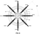
- Fig. 4 and Fig. 7 illustrate aspects of embodiments with 4 pairs.
- the passage 1 is preferably made of dielectric material, for example quartz or high temperature resistive ceramic material, for example boron nitride.
- dielectric material for example quartz or high temperature resistive ceramic material, for example boron nitride.
- a conductive nozzle is not excluded. When electrically conductive, the nozzle may be operated at a floating electrical potential, not directly connected with one of the electrodes being separated from them by a cold primary gas flow boundary layer.
- Conductive nozzles are preferably made of graphite and water cooled (not shown) when being made of metals such as steel and copper.
- the electrodes are oriented under an angle of 45 degrees relative to the z-axis. Envisioned angles are between 30 and 60 degrees or between 60 and 90 degrees. Angles with respect to the z-axis are preferably all equal for different HV electrodes in the same plasma reactor.
- a secondary plasma gas injector 5 is shown, positioned along the vertical z-axis of the plasma reactor. To increase homogeneity of exposure to plasma induced reaction, the injector preferably opens centrally between the electrodes.
- the secondary plasma gas is principally mixing and reacting with the plasma activated primary plasma gas. That is at some distance downstream of the end position of HV electrodes and their respective electrode rod tips 13. This allows primary plasma gas being sufficiently activated before reacting with secondary gas.
- the reactive mixing zone can be confined to the small throat area, thus limiting reaction times.
- the embodiment as shown in Fig. 1 is equipped with a duct element 33, separating primary and secondary gas flows, G1 and G2, directing them to the throat area 2 of the passage 1.
- the duct element 33 is provided downstream of the secondary gas inlet 5, and has a secondary gas channel 7 that has a reduced diameter relative to the upstream secondary gas channel 7. This increases the speed and narrows the flow profile of the secondary gas, thus facilitating mixing of plasma activated gas G1 with secondary gas G2 in a limited volume.
- Plasma activation can be understood as formation of reactive plasma species such as free electrons, ions, radicals, vibrationally and/or electronically excited molecules as well as heating by means of the electrical resistive discharge current.
- Plasma activation is the generic term used independent on the detailed mechanisms forming the reactive plasma species, whether caused by heating, electric impact dissociation or vibrational excitation or a combination of these mechanisms.
- the dominating mechanisms of chemical conversion depend on application specific factors such as the feed stock gas compositions, their flow rates and energy density.
- the spatial stability of arc discharges in general is influenced by gas flow.
- the arc discharges can advantageously possess principally a V-shaped structure.
- Two discharge zones can be distinguished: In the first discharge zone, nearby the electrodes, at least part of the primary plasma gas is activated.
- the repetitive arc discharge is stabilized by the relative cold gas flow enveloping the arc channels.
- Arc stabilization is understood here as repetitively generated arcs with reproducible linear structure and following approximatively identical spatial paths.
- This first discharge zone corresponds to the two 'legs' of the V-shape.
- the arc current crosses the main flow direction. In this area the arc is more sensitive to flow.
- the repetitive arc channel paths may move in the direction of flow with a characteristic gliding-arc re-ignition frequency, lower than the arc repetition rate frequency.
- the gliding arc phenomenon under repetitive pulsed arc conditions is known from literature.
- the pointed area of the V-shaped arc remains relatively small with respect to the total arc length.
- the V-shape is relatively sharp.
- the flow velocity towards the throat can be strongly accelerated by the combined effects of decreasing flow aperture, heating and chemical dissociation.
- a fast temperature decrease may be desired to reduce side reactions. Quenching ideally occurs by endothermic chemical conversion reactions. Additional quenching may be achieved by injecting a quench fluid flow G3, e.g. a gas or quench liquid, leading to additional physical quenching, additional chemical quenching or a combination of those factors.
- the plasma reactor 100 comprises one or more further inlets 8 for injecting one or more quench gas flows G3.
- the quench gas is preferably injected between the throat area 2 and the reactor outlet 3.
- a distribution element e.g. distributing ring 9, can be provided.
- the reactor, housing and further components can be manufactured from known materials, preferably materials known to withstand the conditions during operation. Cooling, e.g. wall cooling, may be provided as needed. Reactor wall parts may be made from one or more of metal, ceramic, and polymer compositions and/or composites.
- the secondary gas flow G2 is distributed along an angular opening using a flow shaping element 6.
- the flow shaping element 6 allows for injection of the secondary gas G2 in the downstream section of V-shaped arc plasma channels using a larger number of electrode pairs within a single reactor unit, see Fig. 3 and 4 .
- electrode rods 11 can be automatically fed to the plasma chamber via electrode tubes 12. Electrodes 10 are mounted in a wall 27 of a dielectric material, e.g. a coating, separating the plasma zones (P1, P2, ...) from an electrode feeding chamber 28.
- the electrode feeding chamber is made of cover plate 24, bottom plate 25 and side wall 26.
- the electrode feeding chamber can be used in addition for stocking and automatic replacement (not shown) of electrode materials.
- the electrode feeding chamber can be pressurized with inert gas to a pressure level corresponding the pressure of the primary gas G1, via gas inlet 29. Alternatively, gas inlet 29 can be used as inlet for primary gas G1.
- the consumption of electrode rod material by operating the pulsed arc discharges with repetitive HV pulses, is strongly reduced when compared with electrode rod consumption needed for DC or line frequency AC arc operation at the same power.
- the time-averaged voltage is higher and the time-averaged current is lower which is beneficial for the reduction of erosion.
- a reactor such as shown in Fig. 3 can be operated with a larger number of electrodes in parallel which is beneficial for increasing the operating time before electrode replacement becomes necessary.
- the reactor further comprises a diverging flow element (23), e.g. as shown in Fig. 3 .
- the gas flow can continue to be accelerated by the pressure gradient.
- the plasma heated and dissociated gas flowing through the converging nozzle passage can be accelerated to Mach number 1 in the throat area. Then, downstream the throat area the gas flow becomes supersonic.
- the physical expansion of the gas can be used for faster cooling and thereby extremely fast quenching of chemical reactions. When velocities are slowed down heat may be released again. In addition, radical recombination reactions may cause heating.
- active quenching e.g. by injecting feed-stock materials may be still desired, e.g. as shown in Fig. 3 .
- Fig. 4 shows a top view of the passage. According to the proposed invention, more than one arc discharges are created in the converging reaction volume, using at least two pairs of electrodes. In the example shown in Fig. 4 , four plasma channels are formed from 4 electrode pairs.
- Fig. 4 shows, in an indicative manner, how primary gas flow G1 leaving electrode gas tubes, can first diverge and again converge when approaching the throat area 2.
- An angle ( ⁇ ) between adjacent electrodes can depend on a total number of electrodes.
- the angle ( ⁇ ) between adjacent electrodes can be smaller than the angle between arc forming electrodes within a single pair. This allows for placing adjacent arc forming pairs closer to each other, thus obtaining a more uniform plasma treatment of primary gas G1.
- the reaction volume can be understood as being defined by the converging volume section of the dielectric passage wherein plasma activated gases from different HV electrodes mix to a single flow towards the circular throat area.
- the tubular jacket 11 is configured to provide an asymmetric flow volume 14, 15 around the surface of the rod 12 such that a flow resistance along a converging passage-, or in the shown example nozzle-, facing side of the electrode rod is comparatively smaller than a flow resistance along a side of the rod facing the longitudinal axis of the passage.
- Fig. 5 shows an exemplary embodiment.
- Primary plasma gas may be injected in the reactor with a uniform angular flow distribution along the perimeter of rod shaped HV electrodes.
- different flow distributions may be used for specific functions:
- Fig. 6 shows (part of) an electrical circuit 30 as comprised in the plasma reactor 100.
- the circuit comprises a single transformer 31.
- the transformer is configured to apply HV pulses to two pairs of electrodes (marked 10-1A, 10-1B, respectively 10-2A, 10-2B), thereby generating two repetitive and synchronized repetitively pulsed arc discharges between electrodes pairs, while avoiding unwanted arcs discharges between neighboring electrode pairs.
- each electrode is galvanically decoupled from the circuit.
- each electrode is connected to a single transformer via an identical series capacitor (C1A, C1B, C2A, C2B).
- the capacitors, together with their charging voltage, pulse length and pulse repetition frequency determine the power delivered to each individual arc discharge.
- Neighboring electrodes 10-1A and 10-2A are connected to the same pulse transformer (31) terminal (VA), whereas neighboring electrodes 10-1B and 10-2B are connected to the opposite pulse transformer (31) terminal (VB).
- VA pulse transformer
- VB opposite pulse transformer
- capacitors may be advantageously used as effective and low-cost energy per pulse limiting components.
- one or more of the electrode pairs may be fed from separate pulse transformers.
- one or more of the electrode pairs may be fed from separate pulse transformers.
- the high voltage pulses are used to reignite the arc discharges at the start of each pulse.
- the arc discharge develops mainly in the residual charged and heated channel of previous discharges, in spite of the fact that plasma species and heat are moved away by gas flow.
- repetition rates of at least 10 kHz provided most stable high frequency arc operation.
- the one or more capacitive-resistive voltage divider 32 is provided (only one drawn).
- the voltage divider 32 is connected to electrode marked 10-2A.
- voltage and currents can be processed in real-time and used to determine the degree of erosion per electrode.
- Several means of control can be used: a) Averages values of dV/dt can be used to calculate stray capacitance of the electrode which will increase with gap elongation. Deviations from the preferred capacitance value may thus be used to move the rod in the desired position; b) Alternatively, or in addition, from integrated values of voltage times current, energy per pulse data can be used.
- Fig. 7 shows part of an electrical circuit 30 suited for generation of 4 high frequency, synchronized arc discharges in a single plasma reactor with converging passage and a single throat.
- the paired electrodes may be connected to 4 individual HV pulse generating power supply units. It will be understood that a preferred configuration can depend on the series produced costs of power supplies and the voltage and current switching capabilities of semiconductor switching components such as insulated-gate bipolar transistor (IGBT).
- IGBT insulated-gate bipolar transistor
- a spacing (s2) between tips of the electrodes operating at the same time-varying potential is comparative smaller than a spacing (s1) between tips of neighboring ones of the electrode rods that operate at an arcing potential differential.
- Fig. 8 shows a full bridge IGBT based switching circuit which has been used for demonstration of the parallel operation of arcs in combination with circuits shown in Figs. 6 and 7 .
- Positive pulses are being generated by simultaneously opening switches S1 and S2 during the pulse, before again simultaneously closing them.
- a pulse length of 5 microseconds and a repetition rate in the 10-200 kHz range have been used.
- switches S3 and S4 can be simultaneously opened and closed.
- This circuit can be used to produce repetitive positive polarity pulses, negative polarity pulses or alternating polarity pulses.
- IGBT switches can be replaced by parallel groups of IGBT switches in order to increase the maximum current capabilities.
- a plasma reactor according the invention may be operated at frequencies above 200 kHz, for example at a frequency in the 1-20 MHz range. It is emphasized that, due to an enormous progress in semiconductor-based power electronics, capabilities of those components, driver and control circuits have increased and costs have been reduced.
- the power converters needed for the proposed invention comprise a limited number of commercially available components.
- Fig. 9 shows examples of voltage and current waveforms which can be measured between arc generating electrodes using a circuit as shown in Figs. 6 , 7 and 8 .
- Experimentally applied HV pulse widths can in the 1 - 10 microsecond range, less than the time period between consecutive HV pulses, which are typically in the 10 - 100 microsecond range (10 - 100 kHz pulse repetition rates).
- the reactor as disclosed herein can be operated to repetitively generate arcs that are V-shape structured, that extend towards the throat area of the passage, get close to each other while remaining separated over prolong periods.
- alternating polarity voltage pulses are applied to electrodes comprising series capacitors.
- the figure shows voltage and plasma currents when measured between electrodes without capacitors. Because of the fast build-up of pulsed arc conductivity, the current pulse consists of a forward current peak which is immediately followed by a backward current peak. However, the forward and backward current peaks do not transport an equal charge to the arc channel. A net positive charge is delivered to the plasma arc channel during each applied positive voltage pulse, which is compensated during each applied negative voltage pulse.
- Fig. 10 shows a linear arrangement of electrode pairs according to the proposed invention. Accordingly, elongated plasma reactors can be provided, with higher numbers of arc generating electrode pairs n.
- the operable power range of a plasma reactor unit may be significantly increased.
- the reactor may comprise a number of cylindrical converging passages 1 with circular throat areas 2. In this manner, a control over flow properties may be maintained.
- the reactor as provided herein can be used to advantage for a variety of chemical conversion processes.
- Exemplary processes include:
- a use of the reactor as disclosed herein in the production of: i) olefins; ii) syngas; iii) HCN; or iv) NO and/or NO wherein for the production of olefins the use comprises: providing to the first inlet of the electrodes a feed comprising H 2 or a mixture comprising H 2 and hydrocarbons as a primary gas flow, and providing to the second inlet a feed comprising methane or a mixture of hydrocarbons as a secondary gas flow, wherein for the production of syngas the use comprises: providing to the first inlet of the electrodes a feed comprising H 2 as a primary gas flow, and providing to the second inlet a feed comprising methane and CO 2 as a secondary gas flow, wherein for the production of HCN the use comprises: providing to the first inlet of the electrodes a feed comprising a mixture comprising H 2 and N 2 as a primary gas flow, and providing to the second inlet a feed compris
- dry air as a secondary gas flow, optionally enriched with ozone
- the use preferably comprises recycling part of a H 2 content separated a product flow as received from the reactor outlet to the primary gas flow
- the use preferably comprises recycling part of a H 2 content separated a product flow as received from the reactor outlet to the primary gas flow.
- the secondary and/or the quenching gas flow can comprise, or be replaced by, liquids or a flow of solid particulates or a combination of phases.
- powder materials may be melted and/or evaporated and/or pyrolyzed and further treated using the proposed plasma reactor.
Landscapes
- Chemical & Material Sciences (AREA)
- Health & Medical Sciences (AREA)
- General Health & Medical Sciences (AREA)
- Toxicology (AREA)
- Organic Chemistry (AREA)
- Chemical Kinetics & Catalysis (AREA)
- Physical Or Chemical Processes And Apparatus (AREA)
Priority Applications (2)
| Application Number | Priority Date | Filing Date | Title |
|---|---|---|---|
| EP23207300.7A EP4549012A1 (fr) | 2023-11-01 | 2023-11-01 | Réacteur à plasma pour traitement de gaz |
| PCT/NL2024/050603 WO2025095778A1 (fr) | 2023-11-01 | 2024-10-31 | Réacteur à plasma pour traitement de gaz |
Applications Claiming Priority (1)
| Application Number | Priority Date | Filing Date | Title |
|---|---|---|---|
| EP23207300.7A EP4549012A1 (fr) | 2023-11-01 | 2023-11-01 | Réacteur à plasma pour traitement de gaz |
Publications (1)
| Publication Number | Publication Date |
|---|---|
| EP4549012A1 true EP4549012A1 (fr) | 2025-05-07 |
Family
ID=88647647
Family Applications (1)
| Application Number | Title | Priority Date | Filing Date |
|---|---|---|---|
| EP23207300.7A Withdrawn EP4549012A1 (fr) | 2023-11-01 | 2023-11-01 | Réacteur à plasma pour traitement de gaz |
Country Status (2)
| Country | Link |
|---|---|
| EP (1) | EP4549012A1 (fr) |
| WO (1) | WO2025095778A1 (fr) |
Cited By (1)
| Publication number | Priority date | Publication date | Assignee | Title |
|---|---|---|---|---|
| US20250056706A1 (en) * | 2021-11-22 | 2025-02-13 | Gaia Securities Limited | Apparatus and methods for generating condensed plasmoids |
Families Citing this family (1)
| Publication number | Priority date | Publication date | Assignee | Title |
|---|---|---|---|---|
| CN113851368B (zh) * | 2021-09-22 | 2023-01-31 | 大连理工大学 | 一种在射频磁化容性耦合放电装置中增强放电的方法 |
Citations (6)
| Publication number | Priority date | Publication date | Assignee | Title |
|---|---|---|---|---|
| WO1998030524A1 (fr) | 1997-01-13 | 1998-07-16 | Carbon Resources, Ltd. | Transformation d'hydrocarbures assistee par des arcs electriques glissants |
| CA2660088A1 (fr) | 2005-08-19 | 2007-02-22 | Atlantic Hydrogen Inc. | Decomposition de gaz naturel ou de methane par decharge d'arc froide |
| US20100270142A1 (en) * | 2009-04-23 | 2010-10-28 | Battelle Energy Alliance, Llc | Combustion flame plasma hybrid reactor systems, chemical reactant sources and related methods |
| US20140021035A1 (en) | 2012-07-17 | 2014-01-23 | Drexel University | High power non-thermal plasma system for industrial applications |
| US20170274344A1 (en) * | 2016-03-25 | 2017-09-28 | Panasonic Intellectual Property Management Co., Lt d. | Production apparatus and production method for fine particles |
| US20180290208A1 (en) * | 2017-04-05 | 2018-10-11 | Panasonic Intellectual Property Management Co., Ltd. | Production apparatus and production method for fine particles |
-
2023
- 2023-11-01 EP EP23207300.7A patent/EP4549012A1/fr not_active Withdrawn
-
2024
- 2024-10-31 WO PCT/NL2024/050603 patent/WO2025095778A1/fr active Pending
Patent Citations (6)
| Publication number | Priority date | Publication date | Assignee | Title |
|---|---|---|---|---|
| WO1998030524A1 (fr) | 1997-01-13 | 1998-07-16 | Carbon Resources, Ltd. | Transformation d'hydrocarbures assistee par des arcs electriques glissants |
| CA2660088A1 (fr) | 2005-08-19 | 2007-02-22 | Atlantic Hydrogen Inc. | Decomposition de gaz naturel ou de methane par decharge d'arc froide |
| US20100270142A1 (en) * | 2009-04-23 | 2010-10-28 | Battelle Energy Alliance, Llc | Combustion flame plasma hybrid reactor systems, chemical reactant sources and related methods |
| US20140021035A1 (en) | 2012-07-17 | 2014-01-23 | Drexel University | High power non-thermal plasma system for industrial applications |
| US20170274344A1 (en) * | 2016-03-25 | 2017-09-28 | Panasonic Intellectual Property Management Co., Lt d. | Production apparatus and production method for fine particles |
| US20180290208A1 (en) * | 2017-04-05 | 2018-10-11 | Panasonic Intellectual Property Management Co., Ltd. | Production apparatus and production method for fine particles |
Cited By (1)
| Publication number | Priority date | Publication date | Assignee | Title |
|---|---|---|---|---|
| US20250056706A1 (en) * | 2021-11-22 | 2025-02-13 | Gaia Securities Limited | Apparatus and methods for generating condensed plasmoids |
Also Published As
| Publication number | Publication date |
|---|---|
| WO2025095778A1 (fr) | 2025-05-08 |
Similar Documents
| Publication | Publication Date | Title |
|---|---|---|
| WO2025095778A1 (fr) | Réacteur à plasma pour traitement de gaz | |
| CA2833965C (fr) | Procede de traitement de gaz et dispositif permettant de mettre en oeuvre ledit procede | |
| US4871580A (en) | Method of treating surfaces of substrates with the aid of a plasma | |
| US5131941A (en) | Reaction apparatus and method | |
| US5628881A (en) | High temperature reaction method | |
| CA2937906C (fr) | Ensemble d'etranglement pour gaz plasma et procede | |
| US3009783A (en) | Production of carbon black | |
| JP2020205279A (ja) | プラズマトーチ設計 | |
| US20100201271A1 (en) | Dc arc plasmatron and method of using the same | |
| JP7702060B2 (ja) | プラズマ化学ガス/ガス混合物変換のための方法および装置 | |
| US20140162338A1 (en) | Device and method for producing a cold, homogeneous plasma under atmospheric pressure conditions | |
| CN1011846B (zh) | 精确控制的等离子体产生系统及方法 | |
| JPWO2008072390A1 (ja) | プラズマ生成装置およびプラズマ生成方法 | |
| RU2001115747A (ru) | Способ получения фуллеренсодержащей сажи и устройство для его осуществления | |
| KR200493866Y1 (ko) | 열 플라즈마 토치 | |
| JPH08339893A (ja) | 直流アークプラズマトーチ | |
| US20190358708A1 (en) | Method and apparatus for producing nanoscale materials | |
| US3376211A (en) | Method and apparatus for performing chemical reactions by means of an electric arc | |
| RU2320102C1 (ru) | Плазмотрон для напыления | |
| RU2007147155A (ru) | Способ и устройство плазмохимического синтеза нанообъектов | |
| RU2818187C1 (ru) | Электродуговой плазмотрон и узел кольцевого ввода исходных реагентов в плазмотрон | |
| US20240359976A1 (en) | Device and method for plasma-induced decomposition of alkanes, in particular methane, into carbon and hydrogen | |
| SU1245269A3 (ru) | Способ нагрева газов в электродуговой установке посто нного тока и электродугова установка | |
| Anshakov et al. | Laboratory and technological electric-arc plasma generators | |
| RU2357922C1 (ru) | Плазмохимическая камера для получения оксида азота прямым окислением |
Legal Events
| Date | Code | Title | Description |
|---|---|---|---|
| PUAI | Public reference made under article 153(3) epc to a published international application that has entered the european phase |
Free format text: ORIGINAL CODE: 0009012 |
|
| STAA | Information on the status of an ep patent application or granted ep patent |
Free format text: STATUS: THE APPLICATION HAS BEEN PUBLISHED |
|
| AK | Designated contracting states |
Kind code of ref document: A1 Designated state(s): AL AT BE BG CH CY CZ DE DK EE ES FI FR GB GR HR HU IE IS IT LI LT LU LV MC ME MK MT NL NO PL PT RO RS SE SI SK SM TR |
|
| RAP3 | Party data changed (applicant data changed or rights of an application transferred) |
Owner name: NEDERLANDSE ORGANISATIE VOOR TOEGEPAST-NATUURWETENSCHAPPELIJK ONDERZOEK TNO |
|
| STAA | Information on the status of an ep patent application or granted ep patent |
Free format text: STATUS: THE APPLICATION IS DEEMED TO BE WITHDRAWN |
|
| 18D | Application deemed to be withdrawn |
Effective date: 20251108 |