EP4549026A1 - Agencement de disques pour séparateur centrifuge - Google Patents
Agencement de disques pour séparateur centrifuge Download PDFInfo
- Publication number
- EP4549026A1 EP4549026A1 EP23207359.3A EP23207359A EP4549026A1 EP 4549026 A1 EP4549026 A1 EP 4549026A1 EP 23207359 A EP23207359 A EP 23207359A EP 4549026 A1 EP4549026 A1 EP 4549026A1
- Authority
- EP
- European Patent Office
- Prior art keywords
- disc
- wing elements
- arrangement
- disc arrangement
- conical surface
- Prior art date
- Legal status (The legal status is an assumption and is not a legal conclusion. Google has not performed a legal analysis and makes no representation as to the accuracy of the status listed.)
- Pending
Links
Images


Classifications
-
- B—PERFORMING OPERATIONS; TRANSPORTING
- B04—CENTRIFUGAL APPARATUS OR MACHINES FOR CARRYING-OUT PHYSICAL OR CHEMICAL PROCESSES
- B04B—CENTRIFUGES
- B04B1/00—Centrifuges with rotary bowls provided with solid jackets for separating predominantly liquid mixtures with or without solid particles
- B04B1/04—Centrifuges with rotary bowls provided with solid jackets for separating predominantly liquid mixtures with or without solid particles with inserted separating walls
- B04B1/08—Centrifuges with rotary bowls provided with solid jackets for separating predominantly liquid mixtures with or without solid particles with inserted separating walls of conical shape
-
- B—PERFORMING OPERATIONS; TRANSPORTING
- B04—CENTRIFUGAL APPARATUS OR MACHINES FOR CARRYING-OUT PHYSICAL OR CHEMICAL PROCESSES
- B04B—CENTRIFUGES
- B04B7/00—Elements of centrifuges
- B04B7/08—Rotary bowls
- B04B7/12—Inserts, e.g. armouring plates
- B04B7/14—Inserts, e.g. armouring plates for separating walls of conical shape
Definitions
- the present disclosure relates to a disc arrangement for a centrifugal separator and a centrifugal separator as defined in the introductory parts of the independent claims.
- Centrifugal separators are generally used for separation of liquids and/or solids from a liquid mixture or a gas mixture.
- fluid mixture that is about to be separated is introduced into a rotating bowl and due to the centrifugal forces, heavy particles or denser liquid, such as water, accumulates at the periphery of the rotating bowl whereas less dense liquid accumulates closer to the centre axis of rotation.
- Conical separation discs are stacked in the rotating bowl at a mutual distance to form interspaces between themselves. Spacing members on an inner conical surface of the separation discs form the interspaces between separation discs.
- the separation discs are shaped as a truncated cone and can be made of thin sheet metal. In some separator applications the separation discs can be made of plastics.
- the separation discs are provided with spacing members in order to create interspaces between the adjacent discs when they are arranged in a stack in the separator.
- the disc arranged at the top of the stack, the top disc, is fixated in place and abuts the separator bowl.
- Wing elements can be arranged on an outer conical surface of the top disc, which is arranged at the top of the stack. The wing elements create a distance between the outer conical surface of the top disc and the inner surface of the separator bowl.
- the wing elements Depending on the type of separator and if fluids or particles in fluids are to be separated, fluid passes between the wing elements and further to an outlet of the separator bowl.
- the rotational motion of the discs and thus the wing elements creates fluid pressure of the fluid or gas between the wing elements, which pressure results of a flow of fluid or gas to the outlet.
- the wing elements have the function of creating a distance between the outer conical surface of the top disc and the inner surface of the separator bowl for hygienically reasons.
- the wing elements are welded to the outer conical surface of the top disc.
- the top disc may be arranged with a larger thickness than the separation discs.
- the top disc may be provided with spacing members on an inner conical surface in order to create an interspace between the top disc and the adjacent separator disc when the top disc is arranged in the top of the stack of separator discs in the separator.
- a further problem with the solutions of the prior art is that the number of wing elements welded to the top disc cannot simply be reduced due to the welding joints. Reducing or alter the number of wing elements may change or regulate the flow of fluid between the wing elements.
- a further objective is to achieve a disc arrangement, which provide for an improved balance of the top disc after arranging the wing elements to the top disc.
- a further objective is to achieve a disc arrangement, which comprises a top disc with small sheet thickness.
- a further objective is to achieve a disc arrangement, in which the number of wing elements easily can be changed.
- a disc arrangement for a centrifugal separator comprises: a truncated cone shaped top disc comprising a top circumference, a base circumference, an outer conical surface and an inner conical surface; a neck device attached to the top circumference of the top disc; and at least three wing elements connected to the neck device.
- the wing elements are configured to rest on and extend along the outer conical surface of the top disc.
- the top disc may be made from a work piece of metal, such as a flat, circular disc of metal. Alternatively, the top disc may be made of plastic.
- the completed top disc may have a frustoconical shape, which corresponds to a truncated cone.
- the truncated cone shaped top disc may comprise an opening with a top circumference at the top of the truncated cone.
- the opening at the top of the top disc may be circular.
- the base of the truncated cone shaped top disc may be a circular opening with a base circumference.
- the outer conical surface may be smooth.
- the inner conical surface may be smooth or provided with spacing members.
- the opening at the top of the separation disc and the circular opening at the base of the top disc are configured to be concentric with a common center axis.
- the neck device may be attached to the top disc by a connection device or a suitable fastener element.
- the at least three wing elements may be releasably connected to the neck device.
- the wing elements may be disconnectable from the neck device and replaced by another type of wing elements.
- the other type of wing elements may have a different shape.
- the other type of wing elements may have a larger or smaller extension in the direction of a normal to the outer conical surface.
- the neck device may be provided with bores into which the wing elements extend.
- the neck device may be provided with protrusions or tabs on which the wing elements are connected.
- the neck device may be provided with a central opening, which is configured to concentric with the opening at the top of the top disc.
- the neck device may be provided with channels, which are axially arranged in the neck device.
- the channels in the neck device are configures to convey the separated fluid flowing on the outer conical surface between the wing elements and into the channels in the neck device and further to an outlet of the separator.
- the wing elements may be configured to rest on and extend along the outer conical surface of the top disc.
- the wing elements may thus be separable from the outer surface of the top disc, i.e. not be welded to, or by other means securely fastened to, the outer surface of the top disc.
- the wing elements may have linear contact with the outer conical surface of the top disc.
- the number of wing elements may be selected in view of the type of fluid to be separated and the pressure exerted from the separator bowl when the disc arrangement is arranged in a stack in the separator bowl.
- This disc arrangement may need little or no machining for balancing the disc arrangement. Since the wings are configured to rest on the outer conical surface of the top disc and no welding operation is used, the sheet thickness of the top disc can be reduced. As a result, the number of separation discs in the stack can be increased, which increases the performance of the centrifugal separator. Further, since the wing elements are replaceable, the flow of fluid on the outer conical surface of the top disc can be controlled and adapted to the fluids to be separated. Also, the number of wing elements can easily be changed for regulating the flow of fluid between the wing elements.
- Each wing element may be a rod with a longitudinal extension and be provided with a first end and a second end, wherein the first end of the wing elements is connected to the neck device.
- the rods may be homogenous or provided with a central bore.
- the cross-section of the rods may be adapted to the fluid to be separated.
- the surface of the rods may be smooth or be provided with indentations or grooves.
- the wing elements may have a cylinder shape.
- the cylinder shape of the wing elements may result in a reduced contact surface between the wing element and the outer conical surface of the top disc. This will reduce contamination at the contact area between the wing elements and the top disc.
- the wing elements may have a circular cross-section.
- the circular cross-section reduces the contact surface between the wing element and the outer conical surface of the top disc.
- the circular cross-section simplifies the arrangement of the wing elements on the outer conical surface of the top disc and the connection to the neck device.
- the wing elements may extend from the neck device to a position adjacent to the base circumference of the top disc.
- the wing elements may end at the base circumference of the top disc.
- the wing elements may end at a position on the outer conical surface of the top disc a distance from the base circumference.
- the wing elements and the neck device may comprise threads for the connection of the wing elements with threaded fittings to the neck device.
- the threaded connection simplifies the replacement of the wing elements and may also be used to add or reduce the number of wing elements of the disc arrangement.
- the wing elements may be connected to the neck device by shrink fittings.
- the shrink fitting may reduce contamination into the fitting and thus increase the hygienic aspects of the arrangement.
- the shrink fitting may also be arranged for a replacement of the wing element. Increasing the temperature of the neck devise will release the wing elements from the neck device.
- each wing element may be provided with a tapered point.
- the tapered point will decrease any disturbance in the fluid flow of the separated fluid that flows between the wing elements on the outer conical surface of the top disc.
- the top disc is configured to be arranged at the top in a stack of separation discs in the centrifugal separator.
- the top disc of the disc arrangement may have a similar shape as the separation discs in the stack. However, the top disc may have a lager sheet or wall thickness than the separation discs in the stack. In some centrifugal separator applications the pressure from the separator bowl on the wing elements and on the top disc of the disc arrangement is very high. In order to withstand this pressure the top disc may be provided with an increased sheet or wall thickness.
- the top disc may comprise spacing members on the inner conical surface.
- the spacing members may be integrated in the material of the top disc.
- the spacing members may be a separate member, which is arranged on the inner conical surface of the top disc.
- a centrifugal separator comprising the disc arrangement disclosed herein.
- the centrifugal separator may be configured for separating a mixture of fluids of different densities from each other.
- the centrifugal separator may be configured for separating particles and a liquid phase from a liquid mixture, such as a clarifier.
- the centrifugal separator may comprise a rotatable centrifuge bowl in which the separation takes place; a stack of separation discs arranged in said centrifuge bowl; and wherein said disc arrangement may be arranged as a top disc of said disc stack and in contact with an inner surface of said centrifuge bowl.
- top disc is configured to be arranged at the top in a stack of separation discs in the centrifugal separator.
- the wings of the disc arrangement may have contact with an inner surface of said centrifuge bowl.
- the stack of separation discs may be compressed with a compression force when mounted in said the centrifuge bowl, and wherein said disc arrangement may be arranged such that said wing elements form an element for transmitting the compression force to the compressed stack of separation discs.
- the top disc of the disc arrangement may be similar to the other separation discs in the stack. However, the top disc may have a lager sheet or wall thickness than the separation discs in the stack. In some centrifugal separator applications the pressure from the separator bowl on the wing elements and on the top disc of the disc arrangement is very high. In order to withstand this pressure the top disc is provided with an increased sheet or wall thickness.
- Fig. 1 schematically illustrates a disc arrangement 1 in a view of perspective according to an example.
- the disc arrangement 1 comprises a truncated cone shaped top disc 4.
- a neck device 14 is attached to a top circumference 6 of the top disc 4.
- Wing elements 18 are connected to the neck device 14.
- the wing elements 18 are configured to rest on and extend along an outer conical surface 10 of the top disc 4.
- the wing elements 18 are configured to be arranged with equal mutual distances to each other on the outer conical surface 10 of the top disc 4.
- the disc arrangement 1 is configured to be a component of a centrifugal separator 2, which is described in connection to fig. 7 .
- Fig. 2 schematically illustrates the top disc 4 in a view of perspective according to an example.
- the top disc 4 is shaped as a truncated cone with a top circumference 6, a base circumference 8, an outer conical surface 10 and an inner conical surface 12.
- the top disc 4 comprises a number of spacing members 34 on the inner conical surface 12. When arranging a top disc 4 over a separation disc 5 in a stack of separation discs 5 (see fig. 7 ) the spacing members 34 will achieve a space between the inner conical surface 12 of one of the top disc 4 and the outer conical surface 10 of the separation disc 5.
- Fig. 3 schematically illustrates a cross-section view of a disc arrangement 1 according to an example.
- Each wing element 18 is a rod with a longitudinal extension and is provided with a first end 20 and a second end 22.
- the first end 20 of the wing elements are connected to the neck device 14.
- the wing elements 18 have a cylinder shape and have a circular cross section.
- the wing elements 18 extend from the neck device 14 to a position adjacent to the base circumference 8 of the top disc 4.
- the second end 22 of each wing element 18 is provided with a tapered or rounded point 30.
- Fig. 4 schematically illustrates a detail view of the disc arrangement 1 disclosed in fig. 3 .
- the wing elements 18 and the neck device 14 comprises threads 24 for the connection of the wing elements 18 with threaded fittings 26 to the neck device 14.
- the wing elements 18 are connected to the neck device 14 by shrink fittings 28.
- the spacing members 34 arranged on the inner conical surface 12 of the top disc 4 are disclosed in fig. 4 .
- a first sealing element 38 is arranged between the neck device 14 and the top disc 4.
- the first sealing element 38 may be an O-ring.
- a second sealing element 40 is arranged at the connection between each wing element 18 and the neck device 14.
- the second sealing element 40 may be an O-ring.
- Fig. 5 schematically illustrates an exploded view of a disc arrangement 1 according to an example.
- the wing elements 18 are connected to the neck device 14.
- the wing elements 18 and the neck device 14 can be connected as a unit to the separation disc 4 after the wing elements 18 have been attached to the neck device 14.
- the first sealing element 38 is disclosed in fig. 5 , which is configured to be arranged between the neck device 14 and the top disc 4.
- Fig. 6 schematically illustrates a disc arrangement 1 in a view from above according to an example.
- Twelve wing elements 18 are arranged with equal mutual distances to each other on the outer conical surface 10 of the top disc 4.
- the disc arrangement 1 can comprise more or less than twelve wing elements 18.
- at least three wing elements 18 are arranged with equal mutual distances to each other on the outer conical surface 10 of the top disc 4.
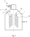
- Fig. 7 schematically illustrates a centrifugal separator 2 according to an example.
- the separator 2 comprises a centrifuge bowl 42 that forms within itself a separation chamber 44 in which centrifugal separation of fluids or particles in fluids takes place during operation.
- the separation chamber 44 is provided with a stack 32 of truncated cone shaped separation discs 5 to facilitate effective separation.
- the disc arrangement 1 is a top disc 4, which is configured to be arranged at the top in a stack 32 of separation discs 5 in the centrifugal separator 2.
Landscapes
- Centrifugal Separators (AREA)
Priority Applications (2)
| Application Number | Priority Date | Filing Date | Title |
|---|---|---|---|
| EP23207359.3A EP4549026A1 (fr) | 2023-11-02 | 2023-11-02 | Agencement de disques pour séparateur centrifuge |
| PCT/EP2024/078737 WO2025093258A1 (fr) | 2023-11-02 | 2024-10-11 | Agencement de disques pour séparateur centrifuge |
Applications Claiming Priority (1)
| Application Number | Priority Date | Filing Date | Title |
|---|---|---|---|
| EP23207359.3A EP4549026A1 (fr) | 2023-11-02 | 2023-11-02 | Agencement de disques pour séparateur centrifuge |
Publications (1)
| Publication Number | Publication Date |
|---|---|
| EP4549026A1 true EP4549026A1 (fr) | 2025-05-07 |
Family
ID=88689978
Family Applications (1)
| Application Number | Title | Priority Date | Filing Date |
|---|---|---|---|
| EP23207359.3A Pending EP4549026A1 (fr) | 2023-11-02 | 2023-11-02 | Agencement de disques pour séparateur centrifuge |
Country Status (2)
| Country | Link |
|---|---|
| EP (1) | EP4549026A1 (fr) |
| WO (1) | WO2025093258A1 (fr) |
Families Citing this family (1)
| Publication number | Priority date | Publication date | Assignee | Title |
|---|---|---|---|---|
| EP3769845B1 (fr) * | 2019-07-26 | 2024-02-28 | Tetra Laval Holdings & Finance S.A. | Séparateur centrifuge |
Citations (2)
| Publication number | Priority date | Publication date | Assignee | Title |
|---|---|---|---|---|
| WO2017144410A1 (fr) * | 2016-02-22 | 2017-08-31 | Alfa Laval Corporate Ab | Rotor centrifuge pour un séparateur centrifuge, séparateur centrifuge, procédé de séparation, et disque conique |
| US20210107014A1 (en) * | 2017-05-02 | 2021-04-15 | Alfa Laval Corporate Ab | A separation disc for a centrifugal separator |
-
2023
- 2023-11-02 EP EP23207359.3A patent/EP4549026A1/fr active Pending
-
2024
- 2024-10-11 WO PCT/EP2024/078737 patent/WO2025093258A1/fr active Pending
Patent Citations (2)
| Publication number | Priority date | Publication date | Assignee | Title |
|---|---|---|---|---|
| WO2017144410A1 (fr) * | 2016-02-22 | 2017-08-31 | Alfa Laval Corporate Ab | Rotor centrifuge pour un séparateur centrifuge, séparateur centrifuge, procédé de séparation, et disque conique |
| US20210107014A1 (en) * | 2017-05-02 | 2021-04-15 | Alfa Laval Corporate Ab | A separation disc for a centrifugal separator |
Also Published As
| Publication number | Publication date |
|---|---|
| WO2025093258A1 (fr) | 2025-05-08 |
Similar Documents
| Publication | Publication Date | Title |
|---|---|---|
| AU624195B2 (en) | Method and plant for freeing a liquid from a substance dispersed therein and having a larger density than the liquid | |
| US11123753B2 (en) | Centrifugal separator with disc having regions of different densities of spacing members | |
| CA3061990C (fr) | Disque de separation pour separateur centrifuge | |
| US11660613B2 (en) | Separation disc for a centrifugal separator having spacing members with a triangular shape | |
| JP3587854B2 (ja) | 円錐状部材の積み重ね体を用いた自己駆動式遠心分離器 | |
| US4721505A (en) | Centrifugal separator | |
| US5575912A (en) | Self-driven, cone-stack type centrifuge | |
| EP4549026A1 (fr) | Agencement de disques pour séparateur centrifuge | |
| US5921909A (en) | Inlet device for a centrifugal separator | |
| JPH01297158A (ja) | 遠心分離機 | |
| EP0824378B1 (fr) | Separateur centrifuge | |
| US4053393A (en) | Cyclone assembly | |
| EP2134474B1 (fr) | Unité compressible pour un séparateur centrifuge | |
| CN1342105A (zh) | 一种用以调节离心分离器的界面的径向水平的方法 | |
| EP3769845B1 (fr) | Séparateur centrifuge | |
| CN218690545U (zh) | 一种溢流量可调节式旋流器 | |
| US5897484A (en) | Centrifugal separator to free a liquid from bath lighter particles and heavier particles | |
| USRE32381E (en) | Cartridge centrifuge | |
| KR102954536B1 (ko) | 원심 분리기 | |
| EP0208761A1 (fr) | Centrifugeuse | |
| KR20240056659A (ko) | 원심 분리기 | |
| KR830000163B1 (ko) | 다중(多重) 하이드로사이클론 장치 |
Legal Events
| Date | Code | Title | Description |
|---|---|---|---|
| PUAI | Public reference made under article 153(3) epc to a published international application that has entered the european phase |
Free format text: ORIGINAL CODE: 0009012 |
|
| STAA | Information on the status of an ep patent application or granted ep patent |
Free format text: STATUS: THE APPLICATION HAS BEEN PUBLISHED |
|
| AK | Designated contracting states |
Kind code of ref document: A1 Designated state(s): AL AT BE BG CH CY CZ DE DK EE ES FI FR GB GR HR HU IE IS IT LI LT LU LV MC ME MK MT NL NO PL PT RO RS SE SI SK SM TR |
|
| STAA | Information on the status of an ep patent application or granted ep patent |
Free format text: STATUS: REQUEST FOR EXAMINATION WAS MADE |
|
| 17P | Request for examination filed |
Effective date: 20251007 |
|
| GRAP | Despatch of communication of intention to grant a patent |
Free format text: ORIGINAL CODE: EPIDOSNIGR1 |
|
| STAA | Information on the status of an ep patent application or granted ep patent |
Free format text: STATUS: GRANT OF PATENT IS INTENDED |
|
| INTG | Intention to grant announced |
Effective date: 20260219 |