EP4549111A1 - Rasierklingeneinheit und rasierapparat damit - Google Patents
Rasierklingeneinheit und rasierapparat damit Download PDFInfo
- Publication number
- EP4549111A1 EP4549111A1 EP24207079.5A EP24207079A EP4549111A1 EP 4549111 A1 EP4549111 A1 EP 4549111A1 EP 24207079 A EP24207079 A EP 24207079A EP 4549111 A1 EP4549111 A1 EP 4549111A1
- Authority
- EP
- European Patent Office
- Prior art keywords
- razor
- blade
- guard
- housing
- cartridge
- Prior art date
- Legal status (The legal status is an assumption and is not a legal conclusion. Google has not performed a legal analysis and makes no representation as to the accuracy of the status listed.)
- Pending
Links
Images





Classifications
-
- B—PERFORMING OPERATIONS; TRANSPORTING
- B26—HAND CUTTING TOOLS; CUTTING; SEVERING
- B26B—HAND-HELD CUTTING TOOLS NOT OTHERWISE PROVIDED FOR
- B26B21/00—Razors of the open or knife type; Safety razors or other shaving implements of the planing type; Hair-trimming devices involving a razor-blade; Equipment therefor
- B26B21/40—Details or accessories
- B26B21/4012—Housing details, e.g. for cartridges
- B26B21/4018—Guard elements
-
- B—PERFORMING OPERATIONS; TRANSPORTING
- B26—HAND CUTTING TOOLS; CUTTING; SEVERING
- B26B—HAND-HELD CUTTING TOOLS NOT OTHERWISE PROVIDED FOR
- B26B21/00—Razors of the open or knife type; Safety razors or other shaving implements of the planing type; Hair-trimming devices involving a razor-blade; Equipment therefor
- B26B21/40—Details or accessories
- B26B21/4012—Housing details, e.g. for cartridges
-
- B—PERFORMING OPERATIONS; TRANSPORTING
- B26—HAND CUTTING TOOLS; CUTTING; SEVERING
- B26B—HAND-HELD CUTTING TOOLS NOT OTHERWISE PROVIDED FOR
- B26B21/00—Razors of the open or knife type; Safety razors or other shaving implements of the planing type; Hair-trimming devices involving a razor-blade; Equipment therefor
- B26B21/40—Details or accessories
- B26B21/4037—Details or parts covering the blades, e.g. caps for storage; Attachments
-
- B—PERFORMING OPERATIONS; TRANSPORTING
- B26—HAND CUTTING TOOLS; CUTTING; SEVERING
- B26B—HAND-HELD CUTTING TOOLS NOT OTHERWISE PROVIDED FOR
- B26B21/00—Razors of the open or knife type; Safety razors or other shaving implements of the planing type; Hair-trimming devices involving a razor-blade; Equipment therefor
- B26B21/40—Details or accessories
- B26B21/4068—Mounting devices; Manufacture of razors or cartridges
-
- B—PERFORMING OPERATIONS; TRANSPORTING
- B26—HAND CUTTING TOOLS; CUTTING; SEVERING
- B26B—HAND-HELD CUTTING TOOLS NOT OTHERWISE PROVIDED FOR
- B26B21/00—Razors of the open or knife type; Safety razors or other shaving implements of the planing type; Hair-trimming devices involving a razor-blade; Equipment therefor
- B26B21/40—Details or accessories
- B26B21/46—Details or accessories for illuminating the skin
-
- B—PERFORMING OPERATIONS; TRANSPORTING
- B26—HAND CUTTING TOOLS; CUTTING; SEVERING
- B26B—HAND-HELD CUTTING TOOLS NOT OTHERWISE PROVIDED FOR
- B26B21/00—Razors of the open or knife type; Safety razors or other shaving implements of the planing type; Hair-trimming devices involving a razor-blade; Equipment therefor
- B26B21/40—Details or accessories
- B26B21/52—Handles, e.g. tiltable, flexible
- B26B21/521—Connection details, e.g. connection to razor heads
-
- B—PERFORMING OPERATIONS; TRANSPORTING
- B26—HAND CUTTING TOOLS; CUTTING; SEVERING
- B26B—HAND-HELD CUTTING TOOLS NOT OTHERWISE PROVIDED FOR
- B26B21/00—Razors of the open or knife type; Safety razors or other shaving implements of the planing type; Hair-trimming devices involving a razor-blade; Equipment therefor
- B26B21/40—Details or accessories
- B26B21/52—Handles, e.g. tiltable, flexible
- B26B21/526—Electric features
-
- B—PERFORMING OPERATIONS; TRANSPORTING
- B26—HAND CUTTING TOOLS; CUTTING; SEVERING
- B26B—HAND-HELD CUTTING TOOLS NOT OTHERWISE PROVIDED FOR
- B26B21/00—Razors of the open or knife type; Safety razors or other shaving implements of the planing type; Hair-trimming devices involving a razor-blade; Equipment therefor
- B26B21/54—Razor-blades
Definitions
- the present disclosure relates to a razor cartridge and a razor assembly including the same, and more specifically, to a razor cartridge accommodating at least one razor blade, and a razor assembly including the razor cartridge and a razor handle.
- a razor is a product for cutting hair such as facial hair or beard, and includes a razor handle for gripping and a razor cartridge having a razor blade that comes into contact with a skin to perform shaving.
- a user when shaving facial beard, a user performs shaving while checking a shaving area through a mirror.
- the user anticipates the shaving area by looking at the lower surface of the razor cartridge through a mirror and proceeds with shaving.
- the razor cartridge includes, in addition to a plurality of razor blades, a configuration for supporting the razor blades, a rubber guard for pulling the skin to be shaved, a lubricating band for applying a lubricating substance to the shaved skin, or the like, it is difficult to accurately determine the position of the razor blades, the condition of the skin to be shaved, or the like during the shaving process.
- An object of the present disclosure is to provide a razor cartridge in which at least a part of a guard region of a razor cartridge is formed of a light transmitting material, and a razor assembly including the same.
- a razor cartridge including: at least one razor blade having a cutting edge formed thereon; a blade housing configured to accommodate the razor blade in a longitudinal direction; and a housing cover including a razor blade window in which at least a portion of the cutting edge is exposed and a window frame formed to surround at least a portion of the razor blade window and connected to the blade housing, in which the window frame includes a plastic guard provided in front of the razor blade, and the plastic guard is formed of a transparent or translucent material.
- a razor assembly including: a razor cartridge; and a razor handle, in which the razor cartridge includes at least one razor blade having a cutting edge formed thereon, a blade housing which accommodates the razor blade in a longitudinal direction and to which the razor handle is coupled, and a housing cover including a razor blade window in which at least a portion of the cutting edge is exposed and a window frame formed to surround at least a portion of the razor blade window and connected to the blade housing, the window frame includes a plastic guard provided in front of the razor blade, and the plastic guard is formed of a light-transmitting material.
- the razor cartridge and the razor assembly according to an embodiment of the present disclosure include the plastic guard formed of a light-transmitting material in the razor cartridge, so that a user can visually confirm the exact position of the razor blade during shaving.
- a razor cartridge and a razor assembly include the plastic guard formed of a light-transmitting material in the razor cartridge, so that light emitted from a light source passes through the plastic guard and is emitted onto the skin, so that a user can accurately recognize the area being shaved, and shaving is possible even in a dark environment.
- symbols such as first, second, i), ii), a), b
- symbols such as first, second, i), ii), a), b
- FIG. 1 is a perspective view illustrating a razor cartridge according to one embodiment of the present disclosure
- FIG. 2 is a bottom view of the razor cartridge according to the embodiment of the present disclosure.
- a razor cartridge 10 according to the embodiment of the present disclosure includes a blade housing 110, a plurality of razor blades 120, and a housing cover 130.
- the blade housing 110 accommodates each razor blade 120 in a longitudinal direction.
- Each razor blade 120 may be arranged in a transverse row.
- the longitudinal direction means a horizontal direction
- the transverse direction means a vertical direction.
- FIGS. 1 and 2 illustrate an example in which six razor blades 120 are included in the razor cartridge 10, the number of razor blades 120 may vary depending on the embodiment.
- An upper surface of the blade housing 110 described below is a surface that comes into contact with or faces a user's skin during a shaving process.
- a lower surface of the blade housing 110 is a surface located on a side opposite to the upper surface, and the lower surface of the blade housing 110 is illustrated in FIG. 2 .
- the rear of the blade housing 110 means upward with reference to FIG. 2 in a direction opposite to the aforementioned front.
- the razor cartridge 10 may include a connector 111 provided on the lower surface of the blade housing 110.
- the connector 111 is configured to be detachably coupled with a razor handle.
- the connector 111 may be coupled to the lower surface of the blade housing 110 or formed integrally with the blade housing 110.
- the connector 111 may include a pair of connecting posts 111a, a pair of guide surfaces 111b, and a connecting groove 111c.
- the pair of connecting posts 111a may be formed to protrude from the blade housing 110 in a state of being longitudinally spaced apart from each other.
- a space between the pair of connecting posts 111a forms a space into which a connecting member of a razor handle, which will be described later, enters.
- the connecting member is a member that is detachably coupled with the connector 111.
- the pair of guide surfaces 111b are provided between the connecting groove 111c and the pair of connecting posts 111a to guide the connecting member of the razor handle to enter the connecting groove 111c.
- the pair of guide surfaces 111b may include a downwardly inclined surface from the pair of connecting posts 111a toward the connecting groove 111c.
- the connecting groove 111c accommodates the connecting member of the razor handle and is detachably coupled with the connecting member.
- the connecting groove 111c may be configured to be hook-coupled to the connecting member a detachable manner.
- the connector 111 may be arranged so as not to overlap with the plurality of razor blades 120. This arrangement relationship allows shaving residue (for example, shaving cream, cut hair, or the like) to be effectively discharged together with the washing water into a space between the plurality of razor blades 120.
- shaving residue for example, shaving cream, cut hair, or the like
- the razor blade 120 is formed with a sharp cutting edge (not illustrated) at an end portion thereof. Referring to FIG. 1 , the razor blade 120 is mounted or supported on the blade housing 110 so that the cutting edge is exposed to the upper surface of the blade housing 110. In addition, the razor blade 120 is mounted or supported on the blade housing 110 so that the cutting edge faces the front of the blade housing 110.
- the housing cover 130 is connected to the blade housing 110 and expands the guard region formed at the front of the razor blade 120.
- the guard region is located at the front of the razor blade 120 and may perform the function of supporting or pulling the skin by coming into contact with the skin before the razor blade 120 during the shaving process.
- the guard region may include a guard bar 115a, an elastic guard 150, and a plastic guard 133a positioned in front of the razor blade 120.
- the plastic guard 133a of the housing cover 130 may be formed of a light-transmitting material. That is, the plastic guard 133a may be formed of a transparent or translucent material.
- the plastic guard 133a of the razor cartridge 10 is formed of a light-transmitting material, the user can visually confirm the exact position of the razor blade 120 during shaving.
- the user can perform shaving while checking the lower surface of the razor cartridge 10 through a mirror.
- the plastic guard 133a of the razor cartridge 10 is formed of a light-transmitting material, the user can visually check the skin supported by the plastic guard 133a during shaving, and accurately recognize the current position of the razor blade 120 and the position of the skin to be shaved by the razor blade 120 later.
- the shaving area and/or the area to be shaved can be visually checked through the plastic guard 133a, thereby enabling safer and more accurate shaving.
- the plastic guard 133a is formed of a light-transmitting material, light emitted from the light can pass through the plastic guard 133a and be emitted to the skin. Therefore, the user can more easily visually check the skin supported by the plastic guard 133a.
- a light source that emits light is provided in the razor handle (see FIG. 10 )
- the light emitted from the razor handle passes through the plastic guard 133a and is emitted onto the skin, so that even in a dark environment, the user can visually check the skin supported by the plastic guard 133a, and thus shaving is possible even in a dark environment.
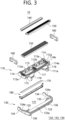
- FIG. 3 is an exploded perspective view of the razor cartridge according to one embodiment of the present disclosure
- FIG. 4 is a perspective view illustrating a cross section of the razor cartridge according to one embodiment of the present disclosure
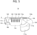
- FIG. 5 is a sectional view of the razor cartridge according to one embodiment of the present disclosure.
- the blade housing 110 includes a rear portion 113 positioned at the rear of the razor blade 120, side portions 114 positioned at each of the two sides of the razor blade 120, and a front portion 115 positioned at the front of the razor blade 120.
- a space between the first razor blade support 112a and the second razor blade support 112b may be formed to penetrate in the up and down direction.
- the space between the first razor blade support 112a and the second razor blade support 112b may be used as a rinsing space in which shaving residue is discharged.
- the rear portion 113 may be formed to connect the side portions 114 on both sides, and a lubricating band accommodating groove 113a for accommodating a lubricating band 140 may be formed on an upper portion of the rear portion 113.
- the lubricating band 140 may be installed so that an upper surface thereof is exposed to the upper surface of the blade housing 110.
- the lubricating band 140 includes a lubricating material and allows the lubricating material to be applied to the skin surface that the razor blade 120 passes through during the shaving process.
- the lubricating material may include ingredients for protecting the skin after shaving.
- a trimmer accommodating groove (not illustrated) for accommodating the trimming blade 170 and the trimmer support 180 may be formed on a lower surface of the rear portion 113.
- the trimmer support 180 is coupled to the rear portion 113 so that the trimming blade 170 is positioned between the trimmer support 180 and the lower surface of the rear portion 113.
- a lubricating material may be applied to a lower surface of the trimmer support 180.
- the front portion 115 may be formed to connect the side portions 114 on both sides, and a guard bar 115a arranged in front of the razor blade 120 may be formed on an upper surface of the front portion 115.
- the guard bar 115a is positioned between the frontmost razor blade and the elastic guard 150.
- the guard bar 115a can support the skin during the shaving process and prevent the skin from being cut by the frontmost razor blade.
- a plane connecting an upper surface of the guard bar 115a and an upper surface of the lubricating band 140 may be defined as a shaving plane S.
- the shaving plane S may be defined as a plane connecting the upper surface of the guard bar 115a and a part of the upper surface of the rear portion 113.
- the cutting edge of the razor blade 120 may be positioned adjacent to the shaving plane S, and at least some of the razor blades 120 may be positioned below the shaving plane S or above the shaving plane S.
- the razor blades positioned at the front may be positioned so that cutting edges have a negative exposure value positioned lower than the shaving plane S to prevent skin cuts
- the razor blades positioned at the rear may be positioned so that cutting edges have a positive exposure value positioned higher than the shaving plane S to ensure a cleaner shave
- the razor blades positioned at the center may be positioned so that cutting edges have an exposure value of 0 positioned on the shaving plane S.
- the blade housing 110 may further include a first guard support 116 extending forward from the front portion 115.
- the first guard support 116 supports the elastic guard 150.
- the elastic guard 150 is in close contact with the user's skin during the shaving process and pulls the skin to improve the shaving effect by the razor blade 120.
- a pattern formed in an embossed or engraved shape may be formed on an upper surface of the elastic guard 150, and the upper surface of the elastic guard 150 may be formed of a material such as rubber or silicone.
- a through slit 117 penetrating in the up and down direction may be formed on the first guard support 116.
- the elastic guard 150 may be inserted into the through slit 117 and exposed through the lower surface of the blade housing 110.
- the through slit 117 may be formed to be located within the connecting groove 111c.
- the elastic guard 150 exposed through the through slit 117 to the lower surface of the blade housing 110 may function as an indicator to visually confirm the entry position of the razor handle within the connecting groove 111c.
- the through slit 117 may be formed such that a longitudinal width thereof gradually decreases along the entry direction of the razor handle, and a part of the elastic guard 150 exposed through the through slit 117 to the lower surface of the blade housing 110 may also be configured such that a longitudinal width thereof gradually decreases along the entry direction of the razor handle.
- the elastic guard 150 and the blade housing 110 may be formed in different colors.
- the through slit 117 overlaps with a part of the plastic guard 133a, so that light passing through the plastic guard 133a from the rear of the razor cartridge 10 may be emitted to the front of the razor cartridge 10 through the through slit 117.
- a lower surface of the front portion 115 may be provided with the pair of connecting posts 111a, the pair of guide surfaces 111b, and the connecting groove 111c as described above.
- the housing cover 130 includes a razor blade window 131 through which at least a portion of the cutting edge of the razor blade 120 is exposed, and a window frame 132 formed to surround at least a portion of the razor blade window 131.
- the window frame 132 may include a front frame 133 positioned in front of the razor blade 120 and a side frame 134 positioned on each of both sides of the razor blade 120.
- the side frame 134 may extend rearward from both sides of the front frame 133 and may be coupled to the outer side of the side portion 114 of the blade housing 110.
- the side frame 134 is a part that the user holds with his or her fingers when holding the razor cartridge 10. Since the side frame 134 is coupled to the outside of the side portion 114, it sufficiently separates the finger from the razor blade 120 and prevents the finger from being cut by the razor blade 120.
- the side frame 134 may be formed of a light-transmitting material, thereby expanding a light-transmitting region of the razor cartridge 10.
- the light-transmitting portion of the side frame 134 may extend from the plastic guard 133a.
- the razor cartridge 10 has a newly formed plastic guard region compared to the conventional razor cartridge for light transmission through the plastic guard 133a.
- the plastic guard 133a may have at least a portion of the upper surface formed as an uneven region of an irregular pattern.
- the uneven region may be formed to have a longitudinal surface roughness (Ra) of between 100 and 300 micrometers.
- the plastic guard 133a including the uneven region passes over the skin before the razor blade 120 during the shaving process, removes dead skin cells and/or excessively applied shaving foam attached to the skin or beard, and pulls the skin to improve the shaving effect by the razor blade 120.
- the uneven region may be formed adjacent to the elastic guard 150 within the plastic guard 133a.
- the uneven region may scatter light passing through the plastic guard 133a so that the illuminance of light emitted to the skin becomes uniform overall.
- an upper surface of the plastic guard 133a may be located lower than the shaving plane S, and may be located lower than the cutting edge of the razor blade 120, the guard bar 115a, and/or the upper surface of the elastic guard 150.
- a ratio of the area of the plastic guard 133a to the cartridge front region located in front of the razor blade 120 may be 0.2 to 0.9.
- the cartridge front region may be a concept including the guard bar 115a, the elastic guard 150, and the front frame 133.
- a ratio of the area of the uneven region to the cartridge front region may be 0.2 to 0.3.
- the front frame 133 may further include a second guard support member 135 extending rearwardly from the plastic guard 133a.
- the second guard support member 135 may support the elastic guard 150 together with the first guard support 116.
- the front frame 133 may further include a pair of reinforcing posts 136 extending downwardly.
- the reinforcing posts 136 may each be coupled to the outer side of the connecting post 111a.
- the reinforcing posts 136 and the side frame 134 may increase the contact area between the blade housing 110 and the housing cover 130, thereby strengthening the coupling force between the blade housing 110 and the housing cover 130.
- the housing cover 130 may be formed of a light transmitting material only for the plastic guard 133a, or may be formed of a light transmitting material only for the front frame 133. Alternatively, the housing cover 130 may be formed entirely of a light transmitting material.
- the connector 111 of the blade housing 110 is formed of an opaque material, and when the plastic guard 133a, the front frame 133, or the housing cover 130 is formed of a light-transmitting material, the connector 111 may be more clearly visually distinguished from the lower surface of the razor cartridge 10.
- the blade housing 110 may be formed of an opaque material to be distinguished from the housing cover 130, but depending on the embodiment, the blade housing 110 may also be formed of a light transmitting material.
- FIG. 6 is an exploded perspective view of a razor cartridge according to another embodiment of the present disclosure.
- the blade housing 110 and the housing cover 130 may be formed integrally with a light-transmitting material.
- the lubricating band 340 may have a lubricating material applied to the entire upper surface including step portions on both left and right ends.
- the blade housing 310 includes a rear portion 313 positioned at the rear of the razor blade 120, side portions 314 positioned at each of the two sides of the razor blade 120, and a front portion 315 positioned at the front of the razor blade 120.
- the side portions 314 on both sides may be provided with first razor blade support portions 112a that support and accommodate both sides of the razor blade 120.
- the side portion 314 may be formed so that the clip 360 is secured by covering the first razor blade support 112a without including the clip groove 114a.
- a longitudinal width of the side portion 314 may be formed narrower, and the longitudinal length of the razor cartridge 30 can be designed smaller than the conventional cartridge compared to the longitudinal length of the razor blade 120. This makes the width where the actual hair is cut relatively longer compared to the overall width (longitudinal length) of the razor cartridge 30, and thus enables more intuitive shaving.
- a second razor blade support 112b may be provided to support and accommodate the central portion of the razor blade 120. Since the first razor blade support 112a and the second razor blade support 112b have been described in the above-described embodiment, further description thereof will be omitted.
- the rear portion 313 may be formed to connect the side portions 314 on both sides, and the rear portion 313 may support at least a part of the lubricating band 340.
- the front portion 315 may be formed to connect the side portions 314 on both sides, and a guard bar 115a disposed in front of the razor blade 120 may be formed on the upper surface of the front portion 315. Since the guard bar 115a has been described in the above-described embodiment, further description thereof will be omitted.
- the lower surface of the front portion 315 is formed with the pair of connecting posts 111 a as described above, and although not illustrated, the lower surface of the front portion 315 may be provided with the pair of guide surfaces (111b, see FIG. 2 ) and the connecting groove (111c, see FIG. 2 ).
- the blade housing 310 may further include a guard support 316 extending forward from the guard bar 115a.
- the guard support 316 may support the elastic guard 350.
- the elastic guard 350 may perform a function similar to the elastic guard 150 of the above-described embodiment.
- a through slit 317 penetrating in the up and down direction may be formed in the guard support 316.
- the through slit 317 may be formed to be positioned within the connecting groove (111c, see FIG. 2 ).
- the elastic guard 350 may be configured such that a portion thereof is exposed to the lower surface of the blade housing 310 through the through slit 317. Since the effect of this configuration has been described in the above-described embodiment, further description thereof will be omitted.
- the through slit 317 overlaps a portion of the plastic guard 133a, so that light transmitted through the plastic guard 133a from the rear of the razor cartridge 30 may be emitted to the front of the razor cartridge 10 through the through slit 317.
- the housing cover 330 includes a razor blade window 131 through which at least a portion of the cutting edge of the razor blade 120 is exposed, and a window frame 132 formed to surround at least a portion of the razor blade window 131.
- the window frame 132 may include a front frame 133 positioned in front of the razor blade 120, side frames 134 positioned on both sides of the razor blade 120, and a rear frame 337 positioned in the rear of the razor blade 120.
- the front frame 133 may include a plastic guard 133a and may include an uneven region, similar to the above-described embodiment. Since the front frame 133 has been described in the above-described embodiment, further description thereof will be omitted.
- the side frame 134 connects both sides of the front frame 133 and the rear frame 337, covers the clip 360, and is coupled to the side portion 314. Referring to FIGS. 8 and 9 , a discharge hole 134a is formed in the side frame 134.
- the discharge hole 134a enables the lateral discharge of shaving residue and the lateral inflow of washing water, thereby improving the discharge and washing effects of shaving residue existing between the razor blades 120.
- the housing cover 330 may further include the rear frame 337.
- a lubricating band 340 is mounted on the upper surface of the rear frame 337.
- the rear frame 337 and/or the side frame 134 may include a structure for coupling with the lubricating band 340.
- a trimmer accommodating groove (not illustrated) for accommodating a trimming blade 170 and a trimmer support 180 may be formed on a lower surface of the rear frame 337. Since the trimming blade 170 and the trimmer support 180 have been described in the above-described embodiments, further description thereof will be omitted.
- the housing cover 330 may be formed of a light transmitting material only for the plastic guard 133a, or may be formed of a light transmitting material only for the front frame 133. Alternatively, the housing cover 330 may be formed entirely of a light transmitting material.
- the blade housing 310 may be formed of an opaque material to be distinguished from the housing cover 330, but according to the embodiment, the blade housing 310 may also be formed of a light transmitting material.
- the blade housing 310 and the housing cover 330 may be formed separately and configured to be mutually coupled, but similar to the razor cartridge 20 according to another embodiment, the blade housing 310 and the housing cover 330 may be formed integrally.
- the blade housing 310 and the housing cover 330 may be formed integrally of a light-transmitting material.
- the blade housing 310 is formed of an opaque material, and at least a portion (for example, the front frame 133 or the plastic guard 133a) of the housing cover 330 is formed of a light-transmitting material, and the blade housing 310 and the housing cover 330 may be formed integrally through a method such as double injection molding process.
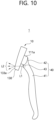
- FIG. 10 is a side view schematically illustrating a razor assembly according to one embodiment of the present disclosure.
- the razor handle 40 includes a handle body 41, a handle head 42, and a light source 43.
- the handle body 41 is a portion that is gripped by the user.
- the handle head 42 is provided at one end of the handle body 41 and is detachably coupled to the connector 111 of the razor cartridge 10, and can rotatably support the coupled razor cartridge 10.
- a connecting member coupled to the connecting groove 111c may be provided at the end portion of the handle head 42.
- the handle body 41 and/or the handle head 42 may be provided with the light source 43 that emits light toward the plastic guard 133a of the razor cartridge 10.
- a battery (not illustrated) that supplies power to the light source 43 may be provided inside the handle body 41, and a switch (not illustrated) that turns the light source 43 ON/OFF may be provided on the outer surface of the handle body 41.
- Light L1 emitted from the light source 43 is incident on the plastic guard 133a from the lower surface of the razor cartridge 10.
- the plastic guard 133a is formed of a light transmitting material, the light L1 incident on the plastic guard 133a passes through the plastic guard 133a and is emitted to the upper surface of the razor cartridge 10.
- the razor assembly 1 can emit light L2 onto the skin just before hair is cut, so that the user can accurately recognize the area where shaving is to be performed, and shave is possible even in a dark environment.
- the razor assembly 1 coupled with the razor cartridge 10 is illustrated and described, the same or similar effects may be achieved in the razor assembly 1 in which the razor cartridges 20 and 30 according to another embodiment is applied instead of the razor cartridge 10 according to one embodiment.
Landscapes
- Life Sciences & Earth Sciences (AREA)
- Forests & Forestry (AREA)
- Engineering & Computer Science (AREA)
- Mechanical Engineering (AREA)
- Health & Medical Sciences (AREA)
- Dermatology (AREA)
- General Health & Medical Sciences (AREA)
- Packaging Of Annular Or Rod-Shaped Articles, Wearing Apparel, Cassettes, Or The Like (AREA)
Applications Claiming Priority (1)
| Application Number | Priority Date | Filing Date | Title |
|---|---|---|---|
| KR1020230139772A KR20250055976A (ko) | 2023-10-18 | 2023-10-18 | 면도기 카트리지 및 이를 포함하는 면도기 조립체 |
Publications (1)
| Publication Number | Publication Date |
|---|---|
| EP4549111A1 true EP4549111A1 (de) | 2025-05-07 |
Family
ID=93154563
Family Applications (1)
| Application Number | Title | Priority Date | Filing Date |
|---|---|---|---|
| EP24207079.5A Pending EP4549111A1 (de) | 2023-10-18 | 2024-10-17 | Rasierklingeneinheit und rasierapparat damit |
Country Status (3)
| Country | Link |
|---|---|
| US (1) | US20250128441A1 (de) |
| EP (1) | EP4549111A1 (de) |
| KR (1) | KR20250055976A (de) |
Families Citing this family (5)
| Publication number | Priority date | Publication date | Assignee | Title |
|---|---|---|---|---|
| USD1107307S1 (en) * | 2023-05-18 | 2025-12-23 | Dorco Co., Ltd. | Razor cartridge |
| USD1109928S1 (en) * | 2023-05-18 | 2026-01-20 | Dorco Co., Ltd. | Razor cartridge |
| USD1107308S1 (en) * | 2023-05-25 | 2025-12-23 | Dorco Co., Ltd. | Razor cartridge |
| USD1110605S1 (en) * | 2023-07-28 | 2026-01-27 | Dorco Co., Ltd. | Razor cartridge |
| USD1108711S1 (en) * | 2024-02-15 | 2026-01-06 | Nfs Capital, Llc | Razor cartridge |
Citations (3)
| Publication number | Priority date | Publication date | Assignee | Title |
|---|---|---|---|---|
| FR1046876A (fr) * | 1951-10-15 | 1953-12-09 | Perfectionnement aux rasoirs | |
| US4473943A (en) * | 1982-09-28 | 1984-10-02 | Sotirios Papanikolaou | Illuminated razor |
| US20200316800A1 (en) * | 2019-04-05 | 2020-10-08 | The Gillette Company Llc | Skin treatment personal care device and method of manufacture |
-
2023
- 2023-10-18 KR KR1020230139772A patent/KR20250055976A/ko not_active Ceased
-
2024
- 2024-10-16 US US18/917,754 patent/US20250128441A1/en active Pending
- 2024-10-17 EP EP24207079.5A patent/EP4549111A1/de active Pending
Patent Citations (3)
| Publication number | Priority date | Publication date | Assignee | Title |
|---|---|---|---|---|
| FR1046876A (fr) * | 1951-10-15 | 1953-12-09 | Perfectionnement aux rasoirs | |
| US4473943A (en) * | 1982-09-28 | 1984-10-02 | Sotirios Papanikolaou | Illuminated razor |
| US20200316800A1 (en) * | 2019-04-05 | 2020-10-08 | The Gillette Company Llc | Skin treatment personal care device and method of manufacture |
Also Published As
| Publication number | Publication date |
|---|---|
| US20250128441A1 (en) | 2025-04-24 |
| KR20250055976A (ko) | 2025-04-25 |
Similar Documents
| Publication | Publication Date | Title |
|---|---|---|
| EP4549111A1 (de) | Rasierklingeneinheit und rasierapparat damit | |
| EP4541534A1 (de) | Rasierklingeneinheit und rasierapparat damit | |
| KR101124752B1 (ko) | 면도기 | |
| EP2611582B1 (de) | Schutzaufsatz für rasierpatrone | |
| RU2314194C1 (ru) | Блок бритвенных лезвий | |
| KR101499287B1 (ko) | 빗살가드 면도기 카트리지 | |
| CN109153138B (zh) | 包括形成有贯通孔的手柄的剃须刀 | |
| SK60794A3 (en) | Razor | |
| US20100071215A1 (en) | Trimmer for shaving razor | |
| US20230158694A1 (en) | Razor cartridge | |
| KR20090024254A (ko) | 면도기 | |
| US10960562B2 (en) | Razor | |
| KR20120026017A (ko) | 초벌 면도와 마무리 면도 겸용 양면면도기 | |
| KR102751636B1 (ko) | 면도기 카트리지 | |
| KR20230081041A (ko) | 면도기 카트리지 | |
| US4835861A (en) | Electric shaver | |
| KR102952360B1 (ko) | 면도기 카트리지 및 이를 포함하는 면도기 조립체 | |
| KR101915762B1 (ko) | 면도날 교체식 면도기 | |
| KR101136349B1 (ko) | 면도기 카트리지 | |
| CN110181564B (zh) | 一种剃须刀头 | |
| RU2741943C2 (ru) | Ручная машинка для стрижки волос | |
| KR20250129418A (ko) | 면도기 조립체 | |
| KR20240170481A (ko) | 면도기 핸들 | |
| JP2000342867A (ja) | 替刃カートリッジ | |
| JP2019063639A (ja) | 電気かみそり |
Legal Events
| Date | Code | Title | Description |
|---|---|---|---|
| PUAI | Public reference made under article 153(3) epc to a published international application that has entered the european phase |
Free format text: ORIGINAL CODE: 0009012 |
|
| STAA | Information on the status of an ep patent application or granted ep patent |
Free format text: STATUS: REQUEST FOR EXAMINATION WAS MADE |
|
| 17P | Request for examination filed |
Effective date: 20241017 |
|
| AK | Designated contracting states |
Kind code of ref document: A1 Designated state(s): AL AT BE BG CH CY CZ DE DK EE ES FI FR GB GR HR HU IE IS IT LI LT LU LV MC ME MK MT NL NO PL PT RO RS SE SI SK SM TR |