EP4549122A1 - Dispositif de serrage magnétique - Google Patents
Dispositif de serrage magnétique Download PDFInfo
- Publication number
- EP4549122A1 EP4549122A1 EP23830953.8A EP23830953A EP4549122A1 EP 4549122 A1 EP4549122 A1 EP 4549122A1 EP 23830953 A EP23830953 A EP 23830953A EP 4549122 A1 EP4549122 A1 EP 4549122A1
- Authority
- EP
- European Patent Office
- Prior art keywords
- magnetizing coil
- circuit
- controller
- instructed
- magnet
- Prior art date
- Legal status (The legal status is an assumption and is not a legal conclusion. Google has not performed a legal analysis and makes no representation as to the accuracy of the status listed.)
- Pending
Links
Images


Classifications
-
- B—PERFORMING OPERATIONS; TRANSPORTING
- B29—WORKING OF PLASTICS; WORKING OF SUBSTANCES IN A PLASTIC STATE IN GENERAL
- B29C—SHAPING OR JOINING OF PLASTICS; SHAPING OF MATERIAL IN A PLASTIC STATE, NOT OTHERWISE PROVIDED FOR; AFTER-TREATMENT OF THE SHAPED PRODUCTS, e.g. REPAIRING
- B29C45/00—Injection moulding, i.e. forcing the required volume of moulding material through a nozzle into a closed mould; Apparatus therefor
- B29C45/17—Component parts, details or accessories; Auxiliary operations
- B29C45/64—Mould opening, closing or clamping devices
-
- B—PERFORMING OPERATIONS; TRANSPORTING
- B29—WORKING OF PLASTICS; WORKING OF SUBSTANCES IN A PLASTIC STATE IN GENERAL
- B29C—SHAPING OR JOINING OF PLASTICS; SHAPING OF MATERIAL IN A PLASTIC STATE, NOT OTHERWISE PROVIDED FOR; AFTER-TREATMENT OF THE SHAPED PRODUCTS, e.g. REPAIRING
- B29C33/00—Moulds or cores; Details thereof or accessories therefor
- B29C33/30—Mounting, exchanging or centering
- B29C33/32—Mounting, exchanging or centering using magnetic means
-
- H—ELECTRICITY
- H01—ELECTRIC ELEMENTS
- H01F—MAGNETS; INDUCTANCES; TRANSFORMERS; SELECTION OF MATERIALS FOR THEIR MAGNETIC PROPERTIES
- H01F13/00—Apparatus or processes for magnetising or demagnetising
-
- H—ELECTRICITY
- H01—ELECTRIC ELEMENTS
- H01F—MAGNETS; INDUCTANCES; TRANSFORMERS; SELECTION OF MATERIALS FOR THEIR MAGNETIC PROPERTIES
- H01F7/00—Magnets
- H01F7/02—Permanent magnets [PM]
- H01F7/04—Means for releasing the attractive force
-
- B—PERFORMING OPERATIONS; TRANSPORTING
- B23—MACHINE TOOLS; METAL-WORKING NOT OTHERWISE PROVIDED FOR
- B23Q—DETAILS, COMPONENTS, OR ACCESSORIES FOR MACHINE TOOLS, e.g. ARRANGEMENTS FOR COPYING OR CONTROLLING; MACHINE TOOLS IN GENERAL CHARACTERISED BY THE CONSTRUCTION OF PARTICULAR DETAILS OR COMPONENTS; COMBINATIONS OR ASSOCIATIONS OF METAL-WORKING MACHINES, NOT DIRECTED TO A PARTICULAR RESULT
- B23Q3/00—Devices holding, supporting, or positioning work or tools, of a kind normally removable from the machine
- B23Q3/15—Devices for holding work using magnetic or electric force acting directly on the work
- B23Q3/154—Stationary devices
- B23Q3/1543—Stationary devices using electromagnets
-
- B—PERFORMING OPERATIONS; TRANSPORTING
- B29—WORKING OF PLASTICS; WORKING OF SUBSTANCES IN A PLASTIC STATE IN GENERAL
- B29C—SHAPING OR JOINING OF PLASTICS; SHAPING OF MATERIAL IN A PLASTIC STATE, NOT OTHERWISE PROVIDED FOR; AFTER-TREATMENT OF THE SHAPED PRODUCTS, e.g. REPAIRING
- B29C45/00—Injection moulding, i.e. forcing the required volume of moulding material through a nozzle into a closed mould; Apparatus therefor
- B29C45/17—Component parts, details or accessories; Auxiliary operations
- B29C45/64—Mould opening, closing or clamping devices
- B29C2045/645—Mould opening, closing or clamping devices using magnetic means
-
- H—ELECTRICITY
- H01—ELECTRIC ELEMENTS
- H01F—MAGNETS; INDUCTANCES; TRANSFORMERS; SELECTION OF MATERIALS FOR THEIR MAGNETIC PROPERTIES
- H01F7/00—Magnets
- H01F7/06—Electromagnets; Actuators including electromagnets
- H01F7/20—Electromagnets; Actuators including electromagnets without armatures
- H01F7/206—Electromagnets for lifting, handling or transporting of magnetic pieces or material
- H01F2007/208—Electromagnets for lifting, handling or transporting of magnetic pieces or material combined with permanent magnets
Definitions
- the present invention relates to a magnetic clamping device that utilizes magnetic adsorption force to clamp/release.
- a current is applied into a coil to generate a magnetic field inside the coil, and the magnet material is supplied into the coil to magnetize the magnet material.
- the direction of the magnetic field depends on the direction of the current flowing through the coil, and the strength of the magnetic field depends on the strength of the current flowing through the coil.
- saturation magnetization is performed, in which the magnet material is magnetized to a limit point "saturation point” at which the magnet material is magnetized.
- Patent Document 1 discloses a capacitor-type magnetizer as an example of such a magnetizer
- alternating current from a high-frequency transformer is rectified in both waves to create a pulsating current, and a charging capacitor is charged in 10 mV increments, and when charging reaches 2.5 kV, the current in the charging capacitor is flowed through to drive a magnetizing coil.
- a series circuit of an SCR, which is a switching element for magnetization, and the magnetizing coil is connected to the charging capacitor, and a flywheel diode is connected in parallel to the series circuit.
- the resonance between the magnetizing coil and the charging capacitor causes the SCR to extinguish due to the reverse voltage after the current has reached the peak and to discharge through the flywheel diode.
- a magnetic clamping device for winding a coil around a magnet material and switching the magnetization/demagnetization in addition to a magnetizer for producing a magnet through the magnet material in the coil For example, a magnetic clamping device for magnetically fixing a mold shown in Patent Document 2 includes a magnet whose polarity cannot be reversed and a magnet material whose polarity can be reversed (alnico magnet), and can switch between a release state in which a magnet uncapable of reversing polarity and a magnet material capable of reversing polarity configure a magnetic circuit closed in series to release a mold, and a lock state in which a magnet uncapable of reversing polarity and a magnet material capable of reversing polarity are connected in parallel to configure a magnetic circuit connected in series with a mold to clamp the mold, by controlling the magnetic polarity of the Alnico magnet by means of a magnetizing coil circulating around the Alnico magnet.
- the capacitor-type magnetizer of Patent Document 1 magnetizes unmagnetized magnet material, in which magnetization is performed by instantaneously flowing current stored in the charging capacitor once.
- the magnet material capable of reversing polarity (alnico magnet) not only reverses the polarity held by itself, but cancels a magnetic flux flowing from adjacent magnets uncapable of reversing polarity. Therefore, sufficient current must continue to flow through a coil wound around the alnico magnet until the magnetic poles of the alnico magnet are reversed and the magnetic flux is saturated.
- large direct current power sources that can keep direct current values for some time intervals are expensive.
- half-wave rectification of the alternating-current power source is used to control the direction of the current by, for example, supplying the upper half-sine wave to the magnetizing coil during clamping and the lower half-sine wave to the magnetizing coil during release, in order to reduce the cost of the power source.
- the half-sine wave is a waveform of only the positive or negative side of the rectified alternating current power source, and a single wave (referred to as a "pulse") of the half-sine wave is about 10 ms. long. A large number of this is applied to the magnetizing coil to generate a magnetic flux.
- the magnetic flux held by the alnico magnet and the magnetic flux flowing in from the magnet uncapable of reversing polarity are added to the generated magnetic flux.
- the polarity of the alnico magnet is gradually reversed, eventually reaching saturation magnetic flux. Therefore, the power is consumed as many times as the number of pulses provided until the magnetic flux is saturated.
- the magnetic clamping device of the present invention includes: a controller; a rectification circuit that performs half-wave rectification on the alternating current power source and supplies positive side pulses to the magnetizing coil of the reversible magnet for a predetermined period when the magnetizing coil is instructed to magnetize by the controller, and supplies a predetermined number of negative side pulses to the magnetizing coil of the reversible magnet when demagnetization is instructed; and a first circulating circuit in which a diode and a switch are connected in series, and the switch is turned on during the period when the magnetizing coil is instructed to magnetize by the controller to form a closed circuit with the magnetizing coil to cause the current generated by the back electromotive force generated by the magnetizing coil to flow circularly and is turned off during the period when the magnetizing coil is instructed to be demagnetized by the controller.
- the mold can be closed and re-magnetized, thereby allowing work to be resumed in a short time.
- FIG. 1 is a view illustrating the injection molding machine 1 and the magnetic clamping devices 10, 20.
- the injection molding machine 1 includes right and left facing platens 2, 3 and a guide rod 9 that guides and supports the left-side platen 2 freely moving forward and backward in right and left directions.
- the magnetic clamping devices 10, 20, which magnetically adsorb the molds, are mounted on the platens 2, 3, respectively.
- Numeral 6 is a nozzle for injecting a resin
- 7 is a controller with an input section and a liquid crystal display screen
- 8 is an ejector rod for extruding an injection molding from a mold.
- the controller 7 controls the magnetic clamping devices 10, 20.
- FIG. 1B is a view of the magnetic clamping device 10 viewed from the side on which the mold is mounted.
- a main body 4 of the magnetic clamping device 10 is made of a ferromagnetic material.
- a large number of magnet blocks 11 made of ferromagnetic material are embedded in the surface side of the main body 4.
- a proximity sensor 12 and a coil for detecting changes in magnetic flux are disposed.
- An ejector rod 8 is inserted into a through-hole 13.
- the magnetic clamping device 20 is almost the same as the magnetic clamping device 10, and its description is omitted. The same applies hereinafter.
- FIG. 1C shows the magnetic clamping device 10 in a demagnetized state.
- a neodymium magnet (non-reversible magnet) 18 surrounds the outer periphery of a magnet block 11 and has, for example, an S-pole toward the magnet block 11 side and an N-pole toward the main body 4 side.
- An alnico magnet (reversible magnet) 16 is a permanent magnet that has an N-pole toward the front side of the magnetic clamping device 10 (upper-side in drawing) and an S-pole toward the back side. Magnetic flux does not leak out to the surface of the magnetic clamping device 10, in which the magnetic flux passes through the magnetic circuit composed of the neodymium magnet 18, the main body 4, the alnico magnet 16, and the magnet block 11, and the mold is not adsorbed.
- FIG. 1D shows the magnetic clamping device 10 in a magnetized state.
- the magnetic pole of the alnico magnet 16 is reversed.
- the alnico magnet 16 is magnetized to form a permanent magnet with the front side of the magnetic clamping device 10 as S-pole and the back side as N-pole.
- both the neodymium magnet 18 and the alnico magnet 16 are coupled to the magnet block 11 as S-poles. With the mold M pressed against the front side of the magnetic clamping device 10, these magnetic fluxes pass through the mold M. Therefore, a magnetic circuit composed of a neodymium magnet 18, a magnet block 11, a mold M and a main body 4, and a magnetic circuit composed of an alnico magnet 16, a magnet block 11, a mold M and a main body 4 are formed, respectively. Once this condition is achieved, the magnetic circuits continue to hold even if the current in the magnetizing coil is cut off. In order to demagnetize the magnetic clamping device 10 from this state, the alnico magnet 16 is demagnetized by passing a negative-side current
- FIG. 2 is a view showing a circuit of the magnetic clamping device 10.
- FIG. 2A shows a power source 30 for the magnetizing coil, wherein the power source 30 is controlled by control signals s0 to s3 of the controller 7.
- the controller 7 generates the control signals s0, s2 when instructing the power source 30 to magnetize the magnetizing coil 17, and generates the control signals s1, s3 when instructing the power source 30 to demagnetize the magnetizing coil 17.
- the power source 30 is connected to a commercial alternating-current power source PS supplied for industrial use and includes a rectification circuit 31, a first circulating circuit 32 and a second circulating circuit 33.
- the rectification circuit 31 is a circuit that performs half-wave rectification on an alternating current, and includes an ignition circuit 38 and thyristors 39, 40.
- the ignition circuit 38 sends a trigger signal to the thyristor 39 when the magnetization of the magnetic clamping device 10 is instructed by the control signal s0.
- An ignition angle is set to a rising period in which the voltage from the alternating-current power source PS increases from 0 V to the positive side, to generate positive-side half-sine wave pulses. Therefore, while the control signal s0 rises, the positive-side pulses are generated continuously.
- the ignition circuit 38 sends a trigger signal to the thyristor 40 when the demagnetization of the magnetic clamping device 10 is instructed by the control signal s1.
- the ignition angle generates negative-side half-sine wave pulses during a falling period in which the voltage from the alternating-current power source PS increases from 0 V to the negative side. Therefore, while the control signal s1 rises, the negative-side pulses are generated continuously.
- the number of consecutive positive-side or negative-side pulses is controlled by controlling the period during which the control signals s0, s1 are rising.
- the pulses generated by the rectification circuit 31 are applied to the magnetization coil 17 as they are.
- energy is stored in the capacitor and then supplied to the magnetizing coil 17, but this embodiment differs in that it is directly supplied to the magnetizing coil 17.
- the first circulating circuit 32 and the second circulating circuit 33 are connected to the magnetizing coil 17 in parallel, respectively.
- the first circulating circuit 32 includes a diode 34 and a switch 35 that are serially connected to each other
- the second circulating circuit 33 includes a diode 36 and a switch 37 that are serially connected to each other.
- the diode 34 and the diode 36 have opposite polarity, with anode and cathode facing opposite directions.
- a first recovery diode (FRD) is used as the diode 34 and the diode 36.
- the switch 35 and the switch 37 are turned on and off by the control signals S2, S3, respectively.
- the control signal S2 turns on the switch 35 during magnetization of the magnetic clamping device 10.
- the control signal S3 turns on the switch 37 during demagnetization of the magnetic clamping device 10.
- a relay circuit is used as the switch 35 and the switch 37.
- FIG. 2B shows waveforms of a voltage v across the magnetizing coil 17, a current i flowing through the magnetizing coil 17 and the control signals s0, s2 in magnetizing.
- the switch 35 is turned on by the control signal s2 (the switch 37 remains off).
- the control signal s0 causes the rectification circuit 31 to generate positive-side pulses v1.
- the control signal s2 causes the first circulating circuit 32 and the magnetizing coil 17 to form a closed circuit.
- the current i1 that attempts to continue flowing due to the back electromotive force of inductance component of the magnetizing coil circulates through the closed circuit is consumed and attenuated by the resistance component of the magnetizing coil 17.
- the inductance component of the magnetizing coil 17 is large, the attenuation of the current i1 becomes gradual, and even when the voltage of the pulses v1 disappears, a relatively large current value can continue to flow. This means that the magnetic flux generated by the magnetizing coil 17 is maintained at a high level.
- FIG. 2C shows a waveform of demagnetization of the magnetizing coil 17.
- the switch 37 is turned on by the control signal s3 (the switch 35 remains off), and the control signal s1 causes the rectification circuit 31 to generate a negative side pulse v2.
- a closed circuit for closing the magnetizing coil 17 is formed by the second circulating circuit 33, and the current i2 flows in a direction opposite to the case of magnetization.
- FIG. 2D shows a waveform of magnetization when the first circulating circuit 32 and the second circulating circuit 33 are not present.
- the current i3 tends to continue flowing for a certain period due to back electromotive force of the inductance component of the magnetizing coil 17, and a negative voltage appears.
- this current i3 enters the rectification circuit 31 and circulates through the magnetization coil 17, making it impossible to sustain the generation of magnetic flux.
- the switch 37 is off when the magnetic clamping device 10 is magnetized, and the switch 35 is off when the magnetic clamping device 10 is demagnetized (the magnetizing coil 17 is demagnetized).
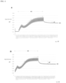
- FIG. 3 shows a magnetic flux density measured by a Tesla meter on the surface of the magnetic clamping device 10 on which the mold is attached. If the remaining magnetic flux density is measured to be the saturation magnetic flux ⁇ s after the current flowing through the magnetizing coil 17 disappears, it is assumed that the magnetic clamp device 10 is normally magnetized.
- FIG. 3A is a case where the first circulating circuit 32 and the second circulating circuit 33 are not provided (comparative example).
- FIG. 3B is a case where the first circulating circuit 32 and the second circulating circuit 33 are provided (experimental example).
- the final residual saturation flux ⁇ s (about 0.05 mT as measured by Tesla meter) is the same in both cases, but the rate of increase in magnetic flux density is faster in FIG. 3B , and almost reaches the upper limit of increase in the latter half.
- the difference d2 in FIG. 3B was clearly larger than the difference d1 in FIG. 3A , indicating that a strong magnetic flux is given to the alnico magnet 16.
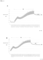
- FIG. 4A is a case where the first circulating circuit 32 and the second circulating circuit 33 are not provided (comparative example).
- FIG. 4B is a case where the first circulating circuit 32 and the second circulating circuit 33 are provided (experimental example). Thirty pulses were supplied to the magnetizing coil 17. The residual saturation magnetic flux ⁇ s is the same in both cases, but both the differences d1 and d2 have decreased, and the difference d1 observed in FIG. 4A is not a sufficient margin for a product.
- FIG. 5 is a case where the first circulating circuit 32 and the second circulating circuit 33 are provided (experimental example). Twenty pulses were supplied to the magnetizing coil 17. The residual magnetic flux density did not reach the saturation flux ⁇ s of Experimental Examples 1 and 2.
- the switch 35 of the first circulating circuit 32 should be turned during magnetizing and turned off during demagnetizing.
- the number of pulses supplied to the magnetizing coil 17 during demagnetizing should be reduced more than the number of pulses during magnetizing.
- the second circulating circuit 33 can be added. Since the rectification circuit 31 does not generate pulses during demagnetizing and non-demagnetizing, the switches 35, 37 can be in either on or off state.
- a closed circuit including the magnetizing coil 17 can be configured by turning on the first circulating circuit 32 at least during the magnetizing period and turning off it at least during the demagnetizing period, to circulate and continue to flow the current using the electromotive force of the magnetizing coil 17 through the magnetizing coil 17 during the period when the pulse is lost, so that the magnetic flux for magnetizing can be maintained in high state. According to this, it is possible to effectively reduce power consumption during magnetizing.
- power consumption can be reduced by reducing the number of pulses supplied to the magnetizing coil 17 during demagnetizing than the number of pulses during magnetizing.
- FIG. 6 shows an application example of the present embodiment. This is an example in which a large number of magnetizing coils 17 are arranged in the magnetic clamping devices 10 and 20, and one power supply system cannot cover the current.
- a power source 30 is provided in which the power supply system from the rectification circuit 31 is four systems.
- the first circulating circuit 32 and the second circulating circuit 33 are connected in series to the magnetizing coil 17 to which electric power is supplied in each system, so that the closed circuit can be formed.
- the first circulating circuit 32 and the second circulating circuit 33 of each system are commonly controlled by the control signals s1 and s2, respectively.
- the controller 7 can directly provide a trigger signal to the thyristors 39 and 40 to directly control the number of positive or negative pulses.
- the thyristors 39 and 40 are used for the rectification circuit 31, other switching elements can be used.
Landscapes
- Engineering & Computer Science (AREA)
- Mechanical Engineering (AREA)
- Power Engineering (AREA)
- Physics & Mathematics (AREA)
- Electromagnetism (AREA)
- Manufacturing & Machinery (AREA)
- Manufacturing Cores, Coils, And Magnets (AREA)
- Jigs For Machine Tools (AREA)
- Relay Circuits (AREA)
Applications Claiming Priority (2)
| Application Number | Priority Date | Filing Date | Title |
|---|---|---|---|
| JP2022106966 | 2022-07-01 | ||
| PCT/JP2023/020414 WO2024004503A1 (fr) | 2022-07-01 | 2023-06-01 | Dispositif de serrage magnétique |
Publications (1)
| Publication Number | Publication Date |
|---|---|
| EP4549122A1 true EP4549122A1 (fr) | 2025-05-07 |
Family
ID=89382683
Family Applications (1)
| Application Number | Title | Priority Date | Filing Date |
|---|---|---|---|
| EP23830953.8A Pending EP4549122A1 (fr) | 2022-07-01 | 2023-06-01 | Dispositif de serrage magnétique |
Country Status (4)
| Country | Link |
|---|---|
| EP (1) | EP4549122A1 (fr) |
| JP (1) | JP2024006891A (fr) |
| CN (1) | CN119384346A (fr) |
| WO (1) | WO2024004503A1 (fr) |
Family Cites Families (4)
| Publication number | Priority date | Publication date | Assignee | Title |
|---|---|---|---|---|
| JPS6056068B2 (ja) * | 1979-01-20 | 1985-12-07 | 株式会社三社電機製作所 | パルス電源装置 |
| JP4667066B2 (ja) | 2005-02-18 | 2011-04-06 | 日本電磁測器株式会社 | 着磁器用電源 |
| EP3782793B1 (fr) | 2018-04-18 | 2023-08-23 | Kosmek Ltd. | Dispositif de fixation magnétique |
| WO2020241090A1 (fr) * | 2019-05-31 | 2020-12-03 | 株式会社コスメック | Procédé de confirmation de force d'adhérence et dispositif de confirmation de force d'adhérence |
-
2022
- 2022-11-25 JP JP2022188103A patent/JP2024006891A/ja active Pending
-
2023
- 2023-06-01 EP EP23830953.8A patent/EP4549122A1/fr active Pending
- 2023-06-01 CN CN202380047626.5A patent/CN119384346A/zh active Pending
- 2023-06-01 WO PCT/JP2023/020414 patent/WO2024004503A1/fr not_active Ceased
Also Published As
| Publication number | Publication date |
|---|---|
| JP2024006891A (ja) | 2024-01-17 |
| CN119384346A (zh) | 2025-01-28 |
| WO2024004503A1 (fr) | 2024-01-04 |
Similar Documents
| Publication | Publication Date | Title |
|---|---|---|
| US11426901B2 (en) | Magnetic clamp device | |
| JP7409697B2 (ja) | 吸着力確認方法及び吸着力確認装置 | |
| US9799438B2 (en) | Method for producing magnet of magnetic encoder | |
| EP0345554B1 (fr) | Dispositif de prise magnétique avec circuit pour éliminer le flux résiduel | |
| US10984936B2 (en) | Electropermanent magnet array | |
| KR101130218B1 (ko) | 영구자석과 전자석을 결합한 자성체 홀딩장치 | |
| KR20120130040A (ko) | 영구자석과 전자석을 결합한 자성체 홀딩장치 | |
| US20050195058A1 (en) | Device and a method for magnetizing a magnet system | |
| GB2069259A (en) | Method and circuit arrangement for demagnetizing permanent magnets | |
| JP6792323B2 (ja) | 磁石を用いた係合システムの着磁制御方法 | |
| EP4549122A1 (fr) | Dispositif de serrage magnétique | |
| US5991147A (en) | Electromagnetic chuck with magnetizing/demagnetizing circuit | |
| JP5264098B2 (ja) | 脱磁装置及び脱磁方法 | |
| RU2187914C2 (ru) | Импульсная система питания индукционного ускорителя | |
| JP4519545B2 (ja) | 可変インダクタンスを有するコイル装置の制御装置、コイルシステム、系統開閉部、及び、コイル装置の制御方法 | |
| JPS62157750A (ja) | 磁気チャックの励磁装置 | |
| JPS6332582B2 (fr) | ||
| JP2006129657A (ja) | 磁気吸着装置の異常検出装置 | |
| SU1483498A1 (ru) | Устройство дл намагничивани и размагничивани элементов магнитных систем импульсным магнитным полем | |
| SU1410114A1 (ru) | Намагничивающее устройство | |
| CN102780372B (zh) | 一种与同步发电机同轴的励磁机充磁装置 | |
| JPH0739118A (ja) | Fddスピンドルモータ用着磁装置 | |
| SK5804Y1 (sk) | Elektropermanentná magnetická upínacia hlavica a elektropermanentný magnetický upínací systém | |
| KR20030069382A (ko) | 횡자속형 단극 착자기 및 그 착자방법 | |
| CZ279981B6 (cs) | Zařízení pro napájení demagnetizátoru |
Legal Events
| Date | Code | Title | Description |
|---|---|---|---|
| STAA | Information on the status of an ep patent application or granted ep patent |
Free format text: STATUS: THE INTERNATIONAL PUBLICATION HAS BEEN MADE |
|
| PUAI | Public reference made under article 153(3) epc to a published international application that has entered the european phase |
Free format text: ORIGINAL CODE: 0009012 |
|
| STAA | Information on the status of an ep patent application or granted ep patent |
Free format text: STATUS: REQUEST FOR EXAMINATION WAS MADE |
|
| 17P | Request for examination filed |
Effective date: 20250120 |
|
| AK | Designated contracting states |
Kind code of ref document: A1 Designated state(s): AL AT BE BG CH CY CZ DE DK EE ES FI FR GB GR HR HU IE IS IT LI LT LU LV MC ME MK MT NL NO PL PT RO RS SE SI SK SM TR |
|
| DAV | Request for validation of the european patent (deleted) | ||
| DAX | Request for extension of the european patent (deleted) |