EP4549187A1 - Système de couvercle enroulable pour un récipient - Google Patents
Système de couvercle enroulable pour un récipient Download PDFInfo
- Publication number
- EP4549187A1 EP4549187A1 EP23207888.1A EP23207888A EP4549187A1 EP 4549187 A1 EP4549187 A1 EP 4549187A1 EP 23207888 A EP23207888 A EP 23207888A EP 4549187 A1 EP4549187 A1 EP 4549187A1
- Authority
- EP
- European Patent Office
- Prior art keywords
- cover
- primary
- displaceable
- shaft
- cover system
- Prior art date
- Legal status (The legal status is an assumption and is not a legal conclusion. Google has not performed a legal analysis and makes no representation as to the accuracy of the status listed.)
- Pending
Links
Images




Classifications
-
- B—PERFORMING OPERATIONS; TRANSPORTING
- B60—VEHICLES IN GENERAL
- B60J—WINDOWS, WINDSCREENS, NON-FIXED ROOFS, DOORS, OR SIMILAR DEVICES FOR VEHICLES; REMOVABLE EXTERNAL PROTECTIVE COVERINGS SPECIALLY ADAPTED FOR VEHICLES
- B60J7/00—Non-fixed roofs; Roofs with movable panels, e.g. rotary sunroofs
- B60J7/08—Non-fixed roofs; Roofs with movable panels, e.g. rotary sunroofs of non-sliding type, i.e. movable or removable roofs or panels, e.g. let-down tops or roofs capable of being easily detached or of assuming a collapsed or inoperative position
- B60J7/085—Non-fixed roofs; Roofs with movable panels, e.g. rotary sunroofs of non-sliding type, i.e. movable or removable roofs or panels, e.g. let-down tops or roofs capable of being easily detached or of assuming a collapsed or inoperative position winding up, e.g. for utility vehicles
Definitions
- the present invention relates to a rollable cover system for covering an open top of a transport body.
- Covers for transport bodies are well-known in the art. Covers for transport bodies, such as a platform on a lorry, a train car, a trailer, a container, etc. are used for covering an open top of the transport body protecting or retaining the transported goods. It is often desirable to have an automated cover system that is easy to operate and install on the transport body. The cover decreases the wind resistance significantly and reduces spill.
- the covers are in many cases equipped with some kind of elastic element as this enables that the container with an open top can be filed such that the material to be transported extend above the open top, see EP 2 505 399 B1 .
- the elastic element may be a pouch extending along the longitudinal direction of the cover, wherein elastic string extends above the pouch for creating a biasing force. The elastic string allows the cover to be tight such that the wind resistance is minimized.
- a cover system allowing the container to be filed from either of the longitudinal sides.
- the cover is rolled to one side by a displaceable arm. See for example EP 2 505 399 B1 .
- Such a system can, in theory, be filed by either side.
- the company or person in charge does not want to be liable for any damages to the cover system thus in practice the filling will only happen in the other side that the rolled-up cover.
- This problem is greatest for trains and train carts as it is relatively easy and possible in most cases for the truck or lorry to perform change orientation 180 degrees, however this is not viable for a train.
- the object of the invention is to provide a cover system for temporarily covering an open area of a container, wherein the cover system can support a top extending higher above the open area without increasing wear or increasing risk of tearing.
- a further object of the invention is to provide a cover system enabling filling of the container from either longitudinal side of the container while the cover is at the other side or at an intermediate position.
- One objective of the invention is achieved by a rollable cover system for temporarily covering an open area of a container.
- the rollable cover system comprises a primary displaceable shaft defining a longitudinal axis, a front side, and a rear side arranged opposite each other and at each end of the first displaceable shaft wherein a top area is defined between the front side and rear side, and comprises a first side and a second side substantially parallel to the longitudinal axis.
- the rollable cover system comprises a primary pivotable arm configured for displacing the primary displaceable shaft between the first side and the second side and a cover attached to the primary displaceable shaft, the cover comprises attachment means configured for being attached to a side.
- the rollable cover system comprises a primary rotary mechanism configured for rotating the primary displaceable shaft about the longitudinal axis for rolling and unrolling the cover when displacing the primary displaceable shaft between the first side and the second side, wherein the rollable cover system has an open state where the top area is exposed, and a closed state where the top area is covered by the cover.
- the rollable cover system is adapted so a width of the cover is greater than the width between the first side and the second side, and the cover comprises two pouches extending substantially parallel to the longitudinal axis, wherein one pouch being closest to the first side and the other pouch being closest to the second side, each pouch being formed by biasing means extending along the cover and the biasing means being configured to create a contracting force substantially perpendicular to the longitudinal axis.
- the container may be part of a transport body or platform on a lorry, a trailer, a train car for holding e.g., a loaded good or any other loose material.
- the rollable cover system When positioned in the open position the rollable cover system is rolled up thereby exposing the open top of the container.
- the container will be able to be loaded or unloaded when in the open position.
- the rollable cover system When positioned in the closed position the rollable cover system is unrolled thereby covering the open top of the container.
- the loaded goods in the container are retained and/or protected during transportation when in the closed position.
- the primary displaceable shaft may be connected to the primary pivotable arm.
- the primary rotary mechanism may be connected to the primary displaceable shaft.
- the cover may be attached to a vertical side of the container or the top of a side of the container.
- the cover may be attached to the side by one or more elastic straps being attached to the side and the cover.
- An advantage of providing the cover with at least two pouches is that the cover becomes flexible towards e.g., a heaped load on the transport body and when the cover is unrolled from the displaceable shaft.
- the cover becomes flexible meaning that the biasing means and the folded pouches may be extended such that an extension of the cover is provided without limited risk of tearing or increase wear due to the two pouches. Thereby accommodating to the additional height of the heaped load and additional stretching of the cover during rolling and un-rolling compared to the prior art, and thus improving the durability of the cover.
- a secondary shaft may extend parallel to the longitudinal axis, wherein the cover is attached to the secondary shaft and wherein one pouch is arranged close to the secondary shaft, and the other pouch is close to the first displaceable shaft.
- the secondary shaft may be arranged between and in connection with the front side and the rear side of the rollable cover system.
- the secondary shaft may be a beam, a bar, boom, rail, plank, etc.
- the two pouches and biasing means are arranged close to the first side and the second side respectively, so that when the rollable cover system is in the closed state the two pouches are within reach for an average person positioned along either the first side or second side, to service and maintain the pouches.
- the pouches are arranged no more than 0.5 meters from the first side or second side.
- An advantage of providing the secondary shaft is that the rollable cover system can be arranged on any given container, as the cover does not need to be attached to a side or a top of a container.
- the rollable cover system may be configured such that it can be mounted at a level on the container which will enable opening of the container at the front side or the rear side. Thereby ensuring that goods can be unloaded through the front side or the rear side of the container, or in general ensuring that there is unhindered access to the container.
- the rollable cover system may comprise:
- the open state can be achieved by at least one of the following shaft positions:
- the cover system enable that the cover can be rolled up to either side or to the intermediate position.
- the cover system may be able to be in all of the three mentioned open positions. This allows filling form in accordance with the further object of the invention.
- the two pouches are a requirement for both arms being pivotal as the pouches are positioned close or near respective displaceable shafts since the rolling of one shaft will cause the nearest pouch to be rolled up. Hence, this pouch cannot provide flexibility during the further displacement of the displaceable shaft and the flexibility is in this case provided by the other pouch and vice versa.
- the requirement for flexibility of the cover is less of a requirement when displacing the displaceable shaft to an intermediate position as the internal stretching will be less.
- the intermediate position enables that the container can be gripped by a large gripper which may afterwards tilt or turn the container upside down as is required for some train carts.
- the intermediate open position may be above a centre of the container i.e., an equal distance from the first side and the second side or at any other position between the first side and the second side.
- the rollable cover system attached to a container of a truck or lorry will enable the truck to be filled from either the first side or the second side by the system being in the open state in form of the second side open position or the first side open position.
- the truck or the lorry will not be able to do a 180-degree turn. This may be the case where a plurality of trucks is in queue to a filling station or where the filling station is at a one-way road such as road at or leading to a motorway.
- the primary and secondary rotary mechanism could be a reel arrangement for winding a wire on and off the primary and secondary displaceable shafts thereby causing rotation.
- the primary and secondary pivotable arm may each be connected to a hydraulic cylinder or electronic actuator or pneumatic cylinder - however, a hydraulic cylinder is preferred.
- a hydraulic cylinder is preferred.
- the pivotable arm may pivot the displaceable shaft 180 degrees between the first side and the second side.
- one or each end of the primary and secondary displaceable shafts is attached to the primary and secondary rotary mechanism and seated in primary and secondary pivotable arms, respectively.
- the rollable cover system may be in the closed state when one of the displaceable shafts is displaced to the first side and the other of the displaceable shafts is displaced to the second side.
- the biasing means may comprise a plurality of elastic straps arranged substantially perpendicular to the longitudinal axis and across the pouches.
- the elastic straps may be separately inserted into holes in the cover.
- the elastic straps may further be arranged substantially perpendicular to the longitudinal axis and substantially parallel to each other.
- the plurality of elastic straps may be made of natural rubber.
- natural rubber is the most wear-resistant and elastic choice of material for the elastic straps.
- the elastic straps may be adjusted so that the contracting force is increased or decreased.
- the biasing means may comprise an elastic strap arranged in a zig-zag pattern across each pouch.
- the zig-zag pattern is arranged substantially parallel with the longitudinal axis so that a contracting force is achieved substantially perpendicular to the longitudinal axis.
- the two elastic straps may be made of natural rubber.
- natural rubber is the most wear-resistant and elastic choice of material for the elastic straps.
- the elastic straps may be adjusted so that the contracting force is increased or decreased.
- a train car with a rollable cover system according to any of claims 1 to 8.
- a truck trailer with a rollable cover system according to any of claims 1 to 8.
- Figure 1 illustrates one embodiment of a rollable cover system 10 with a front side 11a, an opposite rear side 11b, a first side 13a and opposite second side 13b defining a top area 14, arranged on a container 20.
- the rollable cover system comprises a primary displaceable shaft 30a which is arranged substantially parallel with a longitudinal axis 32 and the first side 13a and second side 13b.
- the displaceable shaft 30a is arranged between two primary pivotable arms 60a with a primary rotary mechanism 50a (not shown here) and is configured to be displaced between the first side 13a and the second side 13b.
- a primary rotary mechanism 50a (not shown here) and is configured to be displaced between the first side 13a and the second side 13b.
- a cover 12 is attached to the displaceable shaft 30a and a side 13a, 13b of the container 20.
- the cover 12 is rolled onto and unrolled from the displaceable shaft 30a, when the displaceable shaft 30a is displaced from one side 13a, 13b to the other side 13b,13a.
- three states of the rollable cover system 10 may be achieved:
- FIG 2 illustrates an embodiment of the rollable cover system 10 wherein the pivotable arms and rotary mechanisms are not shown.
- the rollable cover system 10 comprises a primary displaceable shaft 30a arranged at the first side 13a and a secondary shaft 30b arranged at the second side 13b.
- the cover 12 is attached to the primary displaceable shaft 30a in one side and the secondary shaft 30b in the other side.
- the rollable cover system 10 is in the closed state 110, where the top is covered by the cover 12.
- the rollable cover system 10 comprises a cover 12 wherein a width of the cover 12 is greater than the width between the first side 13a and the second side 13b.
- the cover 12 comprises biasing means 16a,16b each arranged closest to each side 13a,13b, wherein the biasing means 16a, 16b are configured to create a contracting force substantially perpendicular to the longitudinal axis 32.
- two pouches 18a, 18b extending substantially parallel to the longitudinal axis 32 are formed by the biasing means 16a,16b.
- the pouches 18a, 18b are expanded when the container 20 is loaded with a heaped load.
- the cover 12 which can elastically expand due to the pouches 18a,18b and biasing means 16a,16b, will conform to the heaped load and thus retain all of the load during transport.
- the pouches 18a,18b and biasing means 16a,16b ensures that the cover 12 is maintained in a position which minimises the aerodynamic drag, e.g. by ensuring that the cover does not flutter or distort from wind and air resistance.
- the biasing means 16a, 16b is an elastic strap arranged in a zig-zag pattern.
- the biasing means 16a,16b may be a plurality of elastic straps arranged substantially parallel to one another and substantially perpendicular to the longitudinal axis 32.
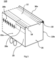
- Figure 3 illustrates one embodiment of the rollable cover system 10 arranged on a container 20, wherein the container comprises a first side panel 22a arranged along the longitudinal axis 32 (not illustrated here) and with an opposite second side panel 22b.
- the two side panels 22a,22b are joined by a rear end 26 of the container.
- the cover 12 may be attached to a side panel 22a,22b of the container 20 by attachment means 28a,28b.
- attachment means 28a is fastening means such as rivets
- attachment means 28b may be a plurality of elastic straps arranged between a side panel 22a,22b and the cover 12, so that the cover can be attached and sufficiently fastened to the side panel 22a,22b.
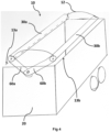
- Figure 4 illustrates one embodiment of the rollable cover system 10 arranged on a container 20 and comprising a primary rotatable arm 60a and a secondary rotatable arm 60b each holding a primary displaceable shaft 30a and a secondary displaceable shaft 30b, respectively.
- the cover 12 is arranged between the primary displaceable shaft 30a and the secondary displaceable shaft 30b, so that when either or both displaceable shafts 30a,30b are displaced and thus rotated by the primary and secondary rotary mechanisms 50a,50b (not illustrated here) about the longitudinal axis, the cover is rolled and unrolled onto either or both of the displaceable shafts 30a,30b.
- the primary and secondary displaceable shafts 30a,30b can both be displaced to the first side 13a and the second side 13b or any intermediate position between the two sides 13a, 13b.
- the open state 100 can be achieved by at least one of the following shaft positions:
- the rollable cover system 10 may also be configured in the closed state 110, when one of the displaceable shafts 30a,30b is displaced to the first side 13a and the other of the displaceable shafts 30b,30a is displaced to the second side 13b, so that the cover 12 covers the entire top area 14.
- FIG. 5a illustrates a rear view of the rollable cover system 10 arranged on a container wherein a rear end 26 of the container 20 is illustrated.
- the rollable cover system 10 comprises a primary pivotable arm 60a connected to a hydraulic cylinder 70, so that the primary pivotable arm 60a can be pivoted about a pivot axis 61 when the hydraulic cylinder 70 is extended or retracted.
- the hydraulic cylinder is fully retracted and as such the primary displaceable shaft 30a is arranged at the first side 13a.
- this position of the primary displaceable shaft 30a may be the open state 100 or the closed state 110.
- the rollable cover system 10 also comprises a primary rotary mechanism 50a arranged at an end of the primary pivotable arm 60a opposite to the pivot axis 61, the primary rotary mechanism 50a is configured to rotate the primary displaceable shaft 30a when the primary displaceable shaft 30a is displaced by the primary pivotable arm 60a from one side 13a, 13b to the other side 13b, 13a.
- Figure 5b illustrates a rollable cover system 10 similar to the rollable cover system illustrated in figure 5a .
- the hydraulic cylinder is fully extracted and as such the primary displaceable shaft 30a is arranged at the second side 13b.
- this position of the primary displaceable shaft 30a may be the open state 100 or the closed state 110.
- Figure 5c illustrates a rollable cover system 10 similar to the rollable cover system illustrated in figure 5a and 5b .
- the hydraulic cylinder is extended to an intermediate length and as such the primary displaceable shaft 30a is arranged at a second intermediate position 103 between the first side 13a and the second side 13b.
- a similar pivotable arm, rotary mechanism and hydraulic cylinder as illustrated in figure 5a, 5b and 5c be provided for the secondary displaceable shaft 30b, the secondary pivotable arm 60b and the secondary rotary mechanism 60b.
- the rollable cover system 10 By displacing both the primary and secondary displaceable shafts 30a,30b to the first side 13a the rollable cover system 10 assumes the open state 100 because the displaceable shafts 30a,30b are in the first side open position 106. Likewise, if the primary and secondary displaceable shafts 30a,30b are displaced to the second side 13b the rollable cover system 10 assumes the open state 100 because the displaceable shafts 30a,30b are in the second side open position 104. By displacing both the primary and secondary displaceable shafts 30a,30b to an intermediate position between the two sides 13a,13b, e.g., above the centre of the top area 14, as illustrated in fig.
- the rollable cover system 10 assumes the open state 100 because the displaceable shafts 30a,30b are in an intermediate open position 102.
Landscapes
- Engineering & Computer Science (AREA)
- Mechanical Engineering (AREA)
- Tents Or Canopies (AREA)
Priority Applications (1)
| Application Number | Priority Date | Filing Date | Title |
|---|---|---|---|
| EP23207888.1A EP4549187A1 (fr) | 2023-11-06 | 2023-11-06 | Système de couvercle enroulable pour un récipient |
Applications Claiming Priority (1)
| Application Number | Priority Date | Filing Date | Title |
|---|---|---|---|
| EP23207888.1A EP4549187A1 (fr) | 2023-11-06 | 2023-11-06 | Système de couvercle enroulable pour un récipient |
Publications (1)
| Publication Number | Publication Date |
|---|---|
| EP4549187A1 true EP4549187A1 (fr) | 2025-05-07 |
Family
ID=88697739
Family Applications (1)
| Application Number | Title | Priority Date | Filing Date |
|---|---|---|---|
| EP23207888.1A Pending EP4549187A1 (fr) | 2023-11-06 | 2023-11-06 | Système de couvercle enroulable pour un récipient |
Country Status (1)
| Country | Link |
|---|---|
| EP (1) | EP4549187A1 (fr) |
Citations (3)
| Publication number | Priority date | Publication date | Assignee | Title |
|---|---|---|---|---|
| US20080231069A1 (en) * | 2007-03-22 | 2008-09-25 | Aero-Kit Industries Inc. | Side roll up tarpaulin system for a flatbed trailer |
| US8641123B1 (en) * | 2013-03-07 | 2014-02-04 | Real Royer | System for covering a vehicle platform |
| EP2505399B1 (fr) | 2011-04-01 | 2020-05-06 | G. J. Holding ApS | Couverture pour une structure de transport |
-
2023
- 2023-11-06 EP EP23207888.1A patent/EP4549187A1/fr active Pending
Patent Citations (3)
| Publication number | Priority date | Publication date | Assignee | Title |
|---|---|---|---|---|
| US20080231069A1 (en) * | 2007-03-22 | 2008-09-25 | Aero-Kit Industries Inc. | Side roll up tarpaulin system for a flatbed trailer |
| EP2505399B1 (fr) | 2011-04-01 | 2020-05-06 | G. J. Holding ApS | Couverture pour une structure de transport |
| US8641123B1 (en) * | 2013-03-07 | 2014-02-04 | Real Royer | System for covering a vehicle platform |
Similar Documents
| Publication | Publication Date | Title |
|---|---|---|
| US6527331B2 (en) | Bow system for a truck cover | |
| US4915439A (en) | Tarpaulin support structure | |
| US6206449B1 (en) | Side-to-side truck cover system | |
| US7549695B2 (en) | Device for manipulating a tarpaulin | |
| US5125713A (en) | Cover for open topped compartments which is movable between stowed and covering positions | |
| US5697663A (en) | Heap climbing container cover system | |
| US3498666A (en) | Rollup load cover apparatus for dump bodies | |
| US5054840A (en) | Method and apparatus for covering open truck beds | |
| US6805395B2 (en) | Tarpaulin rod securing device | |
| US6237985B1 (en) | Cover system for truck containers | |
| US6575518B1 (en) | Flexible cover system for an open-topped container | |
| US20110254310A1 (en) | Device for manipulating a tarpaulin | |
| CA2268605C (fr) | Couvercle d'ecoutille de navire | |
| US5823604A (en) | Cover installation system for open topped containers | |
| US10919368B2 (en) | Apparatus for covering a container load | |
| EP4549187A1 (fr) | Système de couvercle enroulable pour un récipient | |
| US7275780B2 (en) | Dual tarp cover system | |
| US6890020B2 (en) | Trailer particularly suited to hauling crushed and flattened vehicles | |
| US5778815A (en) | Ship hatch cover | |
| US6499790B1 (en) | Covering system for a trailer and method | |
| CA2339471C (fr) | Vehicule comportant des conteneurs de chargement destines a recevoir des marchandises | |
| US20060043755A1 (en) | Truck covering system | |
| CA2589645C (fr) | Manipulateur de bache | |
| DE202009001825U1 (de) | Transportfahrzeug mit doppeltem Verwendungszweck | |
| CA2428891C (fr) | Dispositif de fixation de tige de bache |
Legal Events
| Date | Code | Title | Description |
|---|---|---|---|
| PUAI | Public reference made under article 153(3) epc to a published international application that has entered the european phase |
Free format text: ORIGINAL CODE: 0009012 |
|
| STAA | Information on the status of an ep patent application or granted ep patent |
Free format text: STATUS: THE APPLICATION HAS BEEN PUBLISHED |
|
| AK | Designated contracting states |
Kind code of ref document: A1 Designated state(s): AL AT BE BG CH CY CZ DE DK EE ES FI FR GB GR HR HU IE IS IT LI LT LU LV MC ME MK MT NL NO PL PT RO RS SE SI SK SM TR |
|
| STAA | Information on the status of an ep patent application or granted ep patent |
Free format text: STATUS: REQUEST FOR EXAMINATION WAS MADE |
|
| 17P | Request for examination filed |
Effective date: 20251107 |