EP4549282A1 - Dispositif de mesure pour un véhicule ferroviaire et procédé de détermination côté véhicule d'au moins une valeur caractéristique - Google Patents
Dispositif de mesure pour un véhicule ferroviaire et procédé de détermination côté véhicule d'au moins une valeur caractéristique Download PDFInfo
- Publication number
- EP4549282A1 EP4549282A1 EP23206928.6A EP23206928A EP4549282A1 EP 4549282 A1 EP4549282 A1 EP 4549282A1 EP 23206928 A EP23206928 A EP 23206928A EP 4549282 A1 EP4549282 A1 EP 4549282A1
- Authority
- EP
- European Patent Office
- Prior art keywords
- rail vehicle
- measuring
- wheel
- measuring device
- designed
- Prior art date
- Legal status (The legal status is an assumption and is not a legal conclusion. Google has not performed a legal analysis and makes no representation as to the accuracy of the status listed.)
- Granted
Links
Images

Classifications
-
- B—PERFORMING OPERATIONS; TRANSPORTING
- B61—RAILWAYS
- B61K—AUXILIARY EQUIPMENT SPECIALLY ADAPTED FOR RAILWAYS, NOT OTHERWISE PROVIDED FOR
- B61K9/00—Railway vehicle profile gauges; Detecting or indicating overheating of components; Apparatus on locomotives or cars to indicate bad track sections; General design of track recording vehicles
- B61K9/08—Measuring installations for surveying permanent way
Definitions
- the invention relates to a measuring device for a rail vehicle for determining at least one characteristic value for a grip of a track during travel on the vehicle and further to a method for determining such a characteristic value.
- the grip of a track also known as adhesion, refers to the friction between a rail on the track and the wheel of the rail vehicle. This friction enables the rail vehicle to accelerate or brake. If there is insufficient grip or adhesion, the wheels will spin during acceleration and skid, lock, or slide during braking. This causes the rail vehicle to lose traction or braking power and causes or increases wear or damage to the wheel and rail. Wheel spin or lock during acceleration and braking is monitored and prevented by systems such as wheel slide protection (WSP) systems. However, the energy loss before the wheels slide or lock is not prevented if the driver's driving behavior does not take adhesion into account. The WSP systems therefore only react, but do not prevent.
- WSP wheel slide protection
- the grip of the track can be influenced by various factors, such as weather-related moisture or icing, slippery leaves on the tracks (for example, in autumn), the condition of the tracks or wheels, and even the weight of the rail vehicle. Therefore, it is important to monitor and consider the changing grip. to ensure safe and effective train traffic.
- the well-known railway standards also list various sources from which a characteristic value for the current skid resistance of the track can be derived. These are as follows: Such a characteristic value can be transmitted to the rail vehicle via an interface for a radio connection to a trackside ATO equipment.
- a characteristic value for the grip can come from a train control system such as ETCS (European Train Control System) via a changed speed setting, which is caused by low grip.
- ETCS European Train Control System
- a grip characteristic value can be entered manually by the train driver on the rail vehicle, for example via the ETCS control panel or via separate hardware buttons within the driver's cab.
- the first two adhesion sources come from trackside information (from the traffic management system or from the trackside ETCS equipment - ETCS-TS), which can only provide up-to-date information if the entire line is constantly monitored for adhesion. This could be done on a frequently used line. However, for example, the first vehicle to arrive after a storm in a rural region would only have access to the current adhesion too late because the line does not yet have the adhesion information.
- the driver can only input adhesion when the driver is on board. This is not the case with higher levels of automation. If the grip value in the ATO is higher than the actual grip, the vehicle generates more tractive force than necessary, resulting in energy losses.
- the invention is therefore based on the object of providing a measuring device and a method of the type mentioned at the outset, by means of which a more reliable characteristic value for the grip of the track of a rail vehicle can be determined.
- the inventive solution has the advantage that the characteristic value for skid resistance is determined on-site on the rail vehicle and can be updated at any time. This allows even rapidly changing skid resistance on the track during travel, for example, due to black ice or sudden heavy rain, to be immediately determined and taken into account.
- the measuring wheel is used to establish direct contact with the track.
- the measuring wheel is held by the wheel suspension and attached to the rail vehicle in such a way that the articulated connection of the measuring wheel creates a decoupling from the rail vehicle.
- the pressure medium can thus be used to apply the pressure force and press the measuring wheel against the track.
- the braking device is provided, which generates the braking torque acting on the measuring wheel during the measurement.
- the sensor device detects a measured value representative of the rotation of the measuring wheel, which can then be used to determine the characteristic value for the grip of the track in comparison to the speed of the rail vehicle or a value representative thereof.
- the measuring device can thus have at least one computing device that determines the characteristic value for the grip, taking into account the measured value from the sensor device.
- the computing device determines the characteristic value for the grip directly from the measuring device and not by a unit external to the measuring device, for example, located in the vehicle computer.
- the computing unit can be designed to determine the characteristic value, taking into account a value for the speed of the rail vehicle during the measurement. This has the advantage that the characteristic value can be determined particularly easily, since the speed of the rail vehicle is usually already known.
- the measuring device can have at least one vehicle interface with which the measuring device is designed to be connectable to the rail vehicle, in particular to an ATO device and/or a vehicle bus of the rail vehicle.
- the measuring wheel can be made of a material on the circumference, in particular a synthetic material, which has a higher coefficient of friction than the wheels of the rail vehicle.
- a material on the circumference in particular a synthetic material, which has a higher coefficient of friction than the wheels of the rail vehicle.
- This has the advantage that a reliable measurement is achieved because the measuring wheel has a higher grip on the track than the steel wheel of the rail vehicle.
- the entire measuring wheel or a large part of the measuring wheel can also be made of this material.
- the material can, for example, be rubber or a rubber-like material.
- the pressure medium can be engaged with the wheel suspension and, in particular, be designed as a servomotor.
- a large weight could, for example, load the wheel suspension at a suitable location and press it downwards, or a spring-damper unit could be used to press the axis of rotation of the measuring wheel downwards via the wheel suspension.
- the servomotor design which is arranged, for example, in the joint of the wheel suspension, has the advantage that it can be used to generate the pressure force of the measuring wheel and, on the other hand, to detect a wear-related angular change in the pivot point of the wheel suspension.
- the braking device can be attached to the wheel suspension and comprise at least one brake pad.
- the brake pad For example, supported on the wheel suspension, it can press against the measuring wheel to generate the braking torque.
- the measuring device can have at least one activation device designed to move the measuring wheel from a rest position without contact with the travel path to a measuring position with contact with the travel path.
- an activation device can be implemented, for example, by a servo motor, which can also perform other tasks at the same time, such as applying the contact pressure as already mentioned above.
- Other designs, such as a pneumatic cylinder, are of course also possible. Since the determination of the characteristic value for the grip may not be necessary on a permanent basis, this design can significantly reduce wear on the measuring wheel.
- the measuring device in particular the braking device and the pressure medium, can be designed such that the measuring wheel is braked during the measurement but not completely blocked. This has the advantage that the recorded measured value is highly meaningful.
- the invention further relates to a rail vehicle which, according to the invention, comprises a measuring device according to one of the aforementioned embodiments.
- the ATO device can be configured to control the rail vehicle taking the characteristic value into account. This has the advantage that the ATO device can thereby control the rail vehicle particularly effectively while still being adapted to the current grip of the route.
- a value for the speed of the rail vehicle during the measurement can be taken into account when determining the characteristic value. This has the advantage that the characteristic value can be easily calculated and the speed of the rail vehicle is usually known at this time and does not need to be determined first.
- a value for the friction coefficient of the measuring wheel-track connection and a value for the relative measuring wheel slip can be determined. These values can be taken into account when determining the characteristic value by comparing them with known values for known grip properties. This has the advantage that the characteristic value for grip can be reliably determined.
- a rail vehicle 1 travels in a direction 2 on a route 3, as shown in Figure 1 is shown.
- the Rail vehicle 1 is, for example, a locomotive, a high-speed train, a commuter train, a subway, a tram, or similar.
- the track 3 is typically constructed from parallel steel rails on which the rail vehicle 1 runs with its wheels 4.
- the wheels 4 of rail vehicle 1 are typically made of steel, just as the rails of track 3 are made of steel.
- the connection between rail vehicle 1 and track 3 is thus a steel-to-steel contact or metal-to-metal contact between wheels 4 and track 3. This connection between rail vehicle 1 and track 3 has been historically established, even if its friction behavior in the contact report is inferior to other material combinations.
- the friction behavior in the contact area between rail vehicle 1 and track 3 is also affected by external influences, such as weather-related moisture or ice.
- This grip of track 3 influences the behavior of rail vehicle 1 during acceleration and braking. If the grip of track 3 is low, wheels 4 can spin during acceleration and lock during braking. This results in sliding friction whose coefficient of friction is lower than that of static friction, which prevails without slippage.
- a characteristic value for the grip of the route 3 is entered into the vehicle control system by a train driver, which the train driver determined based on his impression of the route and his experience.
- Future rail vehicles 1 will increasingly be operated autonomously, i.e. without a driver.
- the rail vehicle 1 in the exemplary embodiment illustrated in the figures does not have a driver, but is equipped with an ATO device 5 that automatically controls the rail vehicle 1.
- the rail vehicle 1 according to the invention comprises a measuring device 6 according to the invention, by which the characteristic value for the skid resistance of the track 3 is automatically determined.
- the measuring device 6, which is Figure 2 is shown enlarged, comprises a measuring wheel 7, a wheel suspension 8, a pressure medium 10, a braking device 11 and a sensor device 9.
- the measuring wheel 7 is made, at least on its circumference, of a synthetic rubber-like material whose coefficient of friction is higher than the coefficient of friction of the wheels 4. During a measurement by the measuring device 6, the measuring wheel 7 contacts the rail of the track 3 on its circumference. The measuring wheel 7 is connected to the wheel suspension 8 in its axis of rotation 12.
- the wheel suspension 8 comprises an attachment unit 13, with which it is essentially rigidly connected to the underbody 14 of the rail vehicle 1.
- the connection to the rail vehicle 1 can be implemented in the usual way as a screw connection.
- the wheel suspension comprises a lever unit 15, which is connected to the attachment unit 13 via a pivot joint 16. On the other side, the lever unit 15 is connected to the measuring wheel 7 in the region of the rotation axis 12.
- the pressure medium 10 is arranged on the swivel joint 16 of the wheel suspension and in the exemplary embodiment in Figure 2 designed as a servo motor, which exerts a moment M p on the lever unit 15.
- the servo motor also has the function of an activation device, which is used to move of the measuring wheel from a rest position without contact with the travel path to a measuring position with contact with the travel path during the measurement. This can reduce the wear of the measuring wheel 7.
- the braking device 11 is attached to the lever unit 15 and exerts a substantially constant braking torque T b on the measuring wheel 7 during the measurement.
- the measurement with the measuring device 6 takes place as follows during the travel of the rail vehicle 1:
- the measuring wheel 7 contacts the track 3 and rotates due to the friction between the measuring wheel 7 and the track 3.
- the pressure medium 10 generates a substantially constant contact pressure F z of the measuring wheel 7 against the track 3 via the lever unit 15 with the lever length d.
- the sensor device 9 comprises in the exemplary embodiment in Figure 2 at least one rotation sensor, here a displacement encoder (not shown), which determines the rotation of the measuring wheel 7 about its axis of rotation 12.
- the rotation which is determined very precisely by the sensor device 9, can be used to determine any deceleration of the measuring wheel 7, even if it is very small. For example, a comparison can be made with a non-braked wheel, such as wheel 4 of the rail vehicle 1, or with the speed of the rail vehicle 1.
- the measuring device 6 also includes a computing device 17. This has at least one vehicle interface (not shown) connected to the ATO device 5. Via this interface, the computing device 17 receives the speed v of the rail vehicle 1, which is available to the ATO device 5. Alternatively, the computing device 17 could also receive the speed v via an interface to the vehicle bus of the rail vehicle 1, via which the speed v is also available.
- the device 6 In order to more easily calculate a coefficient of friction ⁇ for the connection of the measuring wheel 7 to the track 3, the device 6 according to the invention causes a temporary braking of the measuring wheel 7 by the braking torque T b .
- the braking torque T b generated by the braking device 11 is adjusted according to the invention such that only a temporary slight braking of the measuring wheel 7 is generated, without the measuring wheel 7 completely blocking.
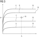
- curves 19 are known during the measurement of the measuring device 6, in particular they are stored in the computing device 17.
- the curves 19 were determined in advance, for example in the laboratory or during other tests.
- the curves 19 show the behavior of the connection between the measuring wheel 7 and the track 3 under different weather conditions or influences.
- curve A represents a dry track 3
- curve B a wet track
- curve C an oily track
- curve D an icy track.
- the computing device 17 now determines which of the curves 19 is closest to the intersection point 18 and then the condition of the nearest curve 19 is set as the characteristic value for the grip of the track 3.
- the characteristic value is therefore assumed to be, for example, the curve A, B, C, D that is closest to the intersection point 18.
- the characteristic value for the grip of the track 3 thus determined is then transmitted to the ATO device 5, which takes this characteristic value into account when calculating the driving curves and braking curves for the rail vehicle 1.
- This characteristic value determined according to the invention for the grip of the track 3 currently prevailing on the rail vehicle 1 can be updated at any time and thus quickly adapts to changing grip conditions.
- the characteristic value The ATO device 5 operating in this way can control the rail vehicle 1 without slippage occurring.
- the characteristic value determined according to the invention can, of course, also be forwarded from the rail vehicle 1 to a control center or another higher-level location. Further processing can take place there.
- the characteristic value can be forwarded to other rail vehicles that are not equipped with the measuring device 6 according to the invention.
- many characteristic values for different locations can be stored over time, creating a map of the rail network on which the characteristic values can be read.
Landscapes
- Engineering & Computer Science (AREA)
- Mechanical Engineering (AREA)
- Electric Propulsion And Braking For Vehicles (AREA)
Priority Applications (1)
| Application Number | Priority Date | Filing Date | Title |
|---|---|---|---|
| EP23206928.6A EP4549282B1 (fr) | 2023-10-31 | 2023-10-31 | Dispositif de mesure pour un véhicule ferroviaire et procédé de détermination côté véhicule d'au moins une valeur caractéristique |
Applications Claiming Priority (1)
| Application Number | Priority Date | Filing Date | Title |
|---|---|---|---|
| EP23206928.6A EP4549282B1 (fr) | 2023-10-31 | 2023-10-31 | Dispositif de mesure pour un véhicule ferroviaire et procédé de détermination côté véhicule d'au moins une valeur caractéristique |
Publications (2)
| Publication Number | Publication Date |
|---|---|
| EP4549282A1 true EP4549282A1 (fr) | 2025-05-07 |
| EP4549282B1 EP4549282B1 (fr) | 2026-05-20 |
Family
ID=88647369
Family Applications (1)
| Application Number | Title | Priority Date | Filing Date |
|---|---|---|---|
| EP23206928.6A Active EP4549282B1 (fr) | 2023-10-31 | 2023-10-31 | Dispositif de mesure pour un véhicule ferroviaire et procédé de détermination côté véhicule d'au moins une valeur caractéristique |
Country Status (1)
| Country | Link |
|---|---|
| EP (1) | EP4549282B1 (fr) |
Citations (7)
| Publication number | Priority date | Publication date | Assignee | Title |
|---|---|---|---|---|
| DE2130385A1 (de) * | 1970-07-02 | 1972-01-13 | Plasser Bahnbaumasch Franz | Fahrbare Einrichtung zur Ermittlung der Spurweite eines Gleises |
| CH653297A5 (en) * | 1981-05-25 | 1985-12-31 | Canron Inc Crissier | Track recording car |
| WO2001071315A1 (fr) * | 2000-03-13 | 2001-09-27 | Hareid Bruktsalg As | Dispositif pour mesurer la friction |
| US20040144167A1 (en) * | 2003-01-27 | 2004-07-29 | Halliday Donald R. | Roadway friction tester and method |
| WO2006037416A1 (fr) * | 2004-10-01 | 2006-04-13 | Franz Plasser Bahnbaumaschinen- Industriegesellschaft Mbh | Machine servant a realiser une correction d'assiette de la voie |
| CN104417583A (zh) * | 2013-08-29 | 2015-03-18 | 中国铁道科学研究院铁道建筑研究所 | 一种实时检测钢轨铣磨车作业精度的装置 |
| EP3012614A1 (fr) * | 2014-10-22 | 2016-04-27 | W.D.M. Limited | Testeur de friction |
-
2023
- 2023-10-31 EP EP23206928.6A patent/EP4549282B1/fr active Active
Patent Citations (7)
| Publication number | Priority date | Publication date | Assignee | Title |
|---|---|---|---|---|
| DE2130385A1 (de) * | 1970-07-02 | 1972-01-13 | Plasser Bahnbaumasch Franz | Fahrbare Einrichtung zur Ermittlung der Spurweite eines Gleises |
| CH653297A5 (en) * | 1981-05-25 | 1985-12-31 | Canron Inc Crissier | Track recording car |
| WO2001071315A1 (fr) * | 2000-03-13 | 2001-09-27 | Hareid Bruktsalg As | Dispositif pour mesurer la friction |
| US20040144167A1 (en) * | 2003-01-27 | 2004-07-29 | Halliday Donald R. | Roadway friction tester and method |
| WO2006037416A1 (fr) * | 2004-10-01 | 2006-04-13 | Franz Plasser Bahnbaumaschinen- Industriegesellschaft Mbh | Machine servant a realiser une correction d'assiette de la voie |
| CN104417583A (zh) * | 2013-08-29 | 2015-03-18 | 中国铁道科学研究院铁道建筑研究所 | 一种实时检测钢轨铣磨车作业精度的装置 |
| EP3012614A1 (fr) * | 2014-10-22 | 2016-04-27 | W.D.M. Limited | Testeur de friction |
Non-Patent Citations (1)
| Title |
|---|
| "AWG Manual", January 2018, article "MANAGING LOW ADHESION" |
Also Published As
| Publication number | Publication date |
|---|---|
| EP4549282B1 (fr) | 2026-05-20 |
Similar Documents
| Publication | Publication Date | Title |
|---|---|---|
| EP3609764B1 (fr) | Assistance à des systèmes d'acheminement de trains par transmission en ligne d'informations concernant la puissance de freinage | |
| EP2741945B1 (fr) | Système de freinage comportant un dispositif de frein électromagnétique sur rail | |
| EP3665048B1 (fr) | Procédé et dispositif pour déterminer des modifications dans le comportement de dynamique longitudinale d'un véhicule ferroviaire | |
| EP3697667B1 (fr) | Procédé pour faire fonctionner des véhicules ferroviaires avec une distance de freinage absolue | |
| EP1298020B1 (fr) | Procédé pour déterminer la masse d'un véhicule automobile en tenant compte des differentes situations de counduit | |
| AT523704B1 (de) | Verfahren und Vorrichtung zum Steuern der Bremsung einer Zahnradbahn | |
| WO2013135393A2 (fr) | Procédé de commande d'un système d'entraînement et de freinage d'un véhicule, comportant un frein à friction | |
| EP2741948A2 (fr) | Système de freinage comportant un dispositif de frein électromagnétique sur rail | |
| EP4301640A1 (fr) | Procédé de détermination d'une vitesse optimale ou maximale autorisée d'un véhicule ferroviaire | |
| WO2018114465A1 (fr) | Procédé permettant de conserver la somme des forces de freinage d'un train en prenant en compte les rapports d'adhérence disponibles | |
| EP3230147B1 (fr) | Procédé pour faire fonctionner une installation de triage par gravité et système de commande pour une telle installation | |
| DE102015110229B4 (de) | Schienenfahrzeugbremssystem und Verfahren zum Betreiben eines Schienenfahrzeugbremssystems | |
| DE102020208797A1 (de) | Verfahren zur Zugsicherung und Zugsicherungseinrichtung | |
| EP3419879B1 (fr) | Procédé et dispositif pour déterminer une puissance de freinage sûre d'un véhicule ferroviaire | |
| DE2006835A1 (de) | Bremseinrichtung fur Schienenfahr zeuge | |
| EP3230148B1 (fr) | Procédé pour faire fonctionner une installation de triage par gravité et système de commande pour une telle installation | |
| EP2054282B1 (fr) | Procédé et système pour activer un essieu libre en conservant la force de freinage | |
| EP1875028A1 (fr) | Procede pour faire fonctionner un dispositif de commande destine a une porte, et dispositif de commande correspondant | |
| DE102013227006A1 (de) | Verfahren zur verteilten Brems- und Beschleunigungsregelung bei einem Zug, Regelungssystem und diesbezügliche Zugeinrichtung | |
| DE102004048993A1 (de) | System und Verfahren zur Steuerung von schienengebundenen Fahrzeugen, insbesondere von Zügen, mittels einer Steuerzentrale, in Abhängigkeit vom Zustand des Fahrwegs, insbesondere des verfügbaren Reibwertes | |
| DE102020205290A1 (de) | Verfahren zum Durchführen einer Spurkranzschmierung | |
| DE102008059893B4 (de) | Verfahren zum Rangieren von schienengebundenen Wagen | |
| DE102022203117A1 (de) | Eisenbahngleisanlage und Verfahren zu deren Betrieb | |
| EP4403425A1 (fr) | Procédé et dispositif de régulation mise en uvre par ordinateur d'un système de freinage d'un véhicule ferroviaire | |
| DE102023201208A1 (de) | Verfahren und Einrichtung zum Erzeugen eines einen Zustand eines Fahrzeugs anzeigenden Zustandssignals |
Legal Events
| Date | Code | Title | Description |
|---|---|---|---|
| PUAI | Public reference made under article 153(3) epc to a published international application that has entered the european phase |
Free format text: ORIGINAL CODE: 0009012 |
|
| STAA | Information on the status of an ep patent application or granted ep patent |
Free format text: STATUS: THE APPLICATION HAS BEEN PUBLISHED |
|
| AK | Designated contracting states |
Kind code of ref document: A1 Designated state(s): AL AT BE BG CH CY CZ DE DK EE ES FI FR GB GR HR HU IE IS IT LI LT LU LV MC ME MK MT NL NO PL PT RO RS SE SI SK SM TR |
|
| RAP3 | Party data changed (applicant data changed or rights of an application transferred) |
Owner name: SIEMENS MOBILITY GMBH |
|
| STAA | Information on the status of an ep patent application or granted ep patent |
Free format text: STATUS: REQUEST FOR EXAMINATION WAS MADE |
|
| 17P | Request for examination filed |
Effective date: 20251006 |
|
| GRAP | Despatch of communication of intention to grant a patent |
Free format text: ORIGINAL CODE: EPIDOSNIGR1 |
|
| STAA | Information on the status of an ep patent application or granted ep patent |
Free format text: STATUS: GRANT OF PATENT IS INTENDED |
|
| INTG | Intention to grant announced |
Effective date: 20251223 |
|
| GRAS | Grant fee paid |
Free format text: ORIGINAL CODE: EPIDOSNIGR3 |
|
| GRAA | (expected) grant |
Free format text: ORIGINAL CODE: 0009210 |
|
| STAA | Information on the status of an ep patent application or granted ep patent |
Free format text: STATUS: THE PATENT HAS BEEN GRANTED |