EP4549312A1 - Procédé de fabrication d'un élément de construction rigidifié en matériau composite et élément de construction - Google Patents
Procédé de fabrication d'un élément de construction rigidifié en matériau composite et élément de construction Download PDFInfo
- Publication number
- EP4549312A1 EP4549312A1 EP24210137.6A EP24210137A EP4549312A1 EP 4549312 A1 EP4549312 A1 EP 4549312A1 EP 24210137 A EP24210137 A EP 24210137A EP 4549312 A1 EP4549312 A1 EP 4549312A1
- Authority
- EP
- European Patent Office
- Prior art keywords
- sub
- layers
- skin
- composite material
- structural component
- Prior art date
- Legal status (The legal status is an assumption and is not a legal conclusion. Google has not performed a legal analysis and makes no representation as to the accuracy of the status listed.)
- Pending
Links
Images



Classifications
-
- B—PERFORMING OPERATIONS; TRANSPORTING
- B29—WORKING OF PLASTICS; WORKING OF SUBSTANCES IN A PLASTIC STATE IN GENERAL
- B29C—SHAPING OR JOINING OF PLASTICS; SHAPING OF MATERIAL IN A PLASTIC STATE, NOT OTHERWISE PROVIDED FOR; AFTER-TREATMENT OF THE SHAPED PRODUCTS, e.g. REPAIRING
- B29C70/00—Shaping composites, i.e. plastics material comprising reinforcements, fillers or preformed parts, e.g. inserts
- B29C70/68—Shaping composites, i.e. plastics material comprising reinforcements, fillers or preformed parts, e.g. inserts by incorporating or moulding on preformed parts, e.g. inserts or layers, e.g. foam blocks
- B29C70/681—Component parts, details or accessories; Auxiliary operations
- B29C70/682—Preformed parts characterised by their structure, e.g. form
-
- B—PERFORMING OPERATIONS; TRANSPORTING
- B29—WORKING OF PLASTICS; WORKING OF SUBSTANCES IN A PLASTIC STATE IN GENERAL
- B29D—PRODUCING PARTICULAR ARTICLES FROM PLASTICS OR FROM SUBSTANCES IN A PLASTIC STATE
- B29D99/00—Subject matter not provided for in other groups of this subclass
- B29D99/001—Producing wall or panel-like structures, e.g. for hulls, fuselages, or buildings
- B29D99/0014—Producing wall or panel-like structures, e.g. for hulls, fuselages, or buildings provided with ridges or ribs, e.g. joined ribs
-
- B—PERFORMING OPERATIONS; TRANSPORTING
- B29—WORKING OF PLASTICS; WORKING OF SUBSTANCES IN A PLASTIC STATE IN GENERAL
- B29C—SHAPING OR JOINING OF PLASTICS; SHAPING OF MATERIAL IN A PLASTIC STATE, NOT OTHERWISE PROVIDED FOR; AFTER-TREATMENT OF THE SHAPED PRODUCTS, e.g. REPAIRING
- B29C70/00—Shaping composites, i.e. plastics material comprising reinforcements, fillers or preformed parts, e.g. inserts
- B29C70/04—Shaping composites, i.e. plastics material comprising reinforcements, fillers or preformed parts, e.g. inserts comprising reinforcements only, e.g. self-reinforcing plastics
- B29C70/28—Shaping operations therefor
- B29C70/30—Shaping by lay-up, i.e. applying fibres, tape or broadsheet on a mould, former or core; Shaping by spray-up, i.e. spraying of fibres on a mould, former or core
- B29C70/32—Shaping by lay-up, i.e. applying fibres, tape or broadsheet on a mould, former or core; Shaping by spray-up, i.e. spraying of fibres on a mould, former or core on a rotating mould, former or core
-
- B—PERFORMING OPERATIONS; TRANSPORTING
- B29—WORKING OF PLASTICS; WORKING OF SUBSTANCES IN A PLASTIC STATE IN GENERAL
- B29C—SHAPING OR JOINING OF PLASTICS; SHAPING OF MATERIAL IN A PLASTIC STATE, NOT OTHERWISE PROVIDED FOR; AFTER-TREATMENT OF THE SHAPED PRODUCTS, e.g. REPAIRING
- B29C70/00—Shaping composites, i.e. plastics material comprising reinforcements, fillers or preformed parts, e.g. inserts
- B29C70/04—Shaping composites, i.e. plastics material comprising reinforcements, fillers or preformed parts, e.g. inserts comprising reinforcements only, e.g. self-reinforcing plastics
- B29C70/28—Shaping operations therefor
- B29C70/40—Shaping or impregnating by compression not applied
- B29C70/42—Shaping or impregnating by compression not applied for producing articles of definite length, i.e. discrete articles
- B29C70/44—Shaping or impregnating by compression not applied for producing articles of definite length, i.e. discrete articles using isostatic pressure, e.g. pressure difference-moulding, vacuum bag-moulding, autoclave-moulding or expanding rubber-moulding
-
- B—PERFORMING OPERATIONS; TRANSPORTING
- B29—WORKING OF PLASTICS; WORKING OF SUBSTANCES IN A PLASTIC STATE IN GENERAL
- B29C—SHAPING OR JOINING OF PLASTICS; SHAPING OF MATERIAL IN A PLASTIC STATE, NOT OTHERWISE PROVIDED FOR; AFTER-TREATMENT OF THE SHAPED PRODUCTS, e.g. REPAIRING
- B29C70/00—Shaping composites, i.e. plastics material comprising reinforcements, fillers or preformed parts, e.g. inserts
- B29C70/04—Shaping composites, i.e. plastics material comprising reinforcements, fillers or preformed parts, e.g. inserts comprising reinforcements only, e.g. self-reinforcing plastics
- B29C70/28—Shaping operations therefor
- B29C70/40—Shaping or impregnating by compression not applied
- B29C70/42—Shaping or impregnating by compression not applied for producing articles of definite length, i.e. discrete articles
- B29C70/44—Shaping or impregnating by compression not applied for producing articles of definite length, i.e. discrete articles using isostatic pressure, e.g. pressure difference-moulding, vacuum bag-moulding, autoclave-moulding or expanding rubber-moulding
- B29C70/446—Moulding structures having an axis of symmetry or at least one channel, e.g. tubular structures, frames
-
- B—PERFORMING OPERATIONS; TRANSPORTING
- B29—WORKING OF PLASTICS; WORKING OF SUBSTANCES IN A PLASTIC STATE IN GENERAL
- B29C—SHAPING OR JOINING OF PLASTICS; SHAPING OF MATERIAL IN A PLASTIC STATE, NOT OTHERWISE PROVIDED FOR; AFTER-TREATMENT OF THE SHAPED PRODUCTS, e.g. REPAIRING
- B29C70/00—Shaping composites, i.e. plastics material comprising reinforcements, fillers or preformed parts, e.g. inserts
- B29C70/68—Shaping composites, i.e. plastics material comprising reinforcements, fillers or preformed parts, e.g. inserts by incorporating or moulding on preformed parts, e.g. inserts or layers, e.g. foam blocks
- B29C70/84—Shaping composites, i.e. plastics material comprising reinforcements, fillers or preformed parts, e.g. inserts by incorporating or moulding on preformed parts, e.g. inserts or layers, e.g. foam blocks by moulding material on preformed parts to be joined
-
- B—PERFORMING OPERATIONS; TRANSPORTING
- B29—WORKING OF PLASTICS; WORKING OF SUBSTANCES IN A PLASTIC STATE IN GENERAL
- B29C—SHAPING OR JOINING OF PLASTICS; SHAPING OF MATERIAL IN A PLASTIC STATE, NOT OTHERWISE PROVIDED FOR; AFTER-TREATMENT OF THE SHAPED PRODUCTS, e.g. REPAIRING
- B29C70/00—Shaping composites, i.e. plastics material comprising reinforcements, fillers or preformed parts, e.g. inserts
- B29C70/68—Shaping composites, i.e. plastics material comprising reinforcements, fillers or preformed parts, e.g. inserts by incorporating or moulding on preformed parts, e.g. inserts or layers, e.g. foam blocks
- B29C70/86—Incorporated in coherent impregnated reinforcing layers, e.g. by winding
-
- B—PERFORMING OPERATIONS; TRANSPORTING
- B64—AIRCRAFT; AVIATION; COSMONAUTICS
- B64C—AEROPLANES; HELICOPTERS
- B64C1/00—Fuselages; Constructional features common to fuselages, wings, stabilising surfaces or the like
- B64C1/06—Frames; Stringers; Longerons ; Fuselage sections
- B64C1/064—Stringers; Longerons
-
- B—PERFORMING OPERATIONS; TRANSPORTING
- B64—AIRCRAFT; AVIATION; COSMONAUTICS
- B64C—AEROPLANES; HELICOPTERS
- B64C1/00—Fuselages; Constructional features common to fuselages, wings, stabilising surfaces or the like
- B64C1/06—Frames; Stringers; Longerons ; Fuselage sections
- B64C1/068—Fuselage sections
-
- B—PERFORMING OPERATIONS; TRANSPORTING
- B29—WORKING OF PLASTICS; WORKING OF SUBSTANCES IN A PLASTIC STATE IN GENERAL
- B29L—INDEXING SCHEME ASSOCIATED WITH SUBCLASS B29C, RELATING TO PARTICULAR ARTICLES
- B29L2031/00—Other particular articles
- B29L2031/30—Vehicles, e.g. ships or aircraft, or body parts thereof
- B29L2031/3076—Aircrafts
- B29L2031/3082—Fuselages
-
- B—PERFORMING OPERATIONS; TRANSPORTING
- B29—WORKING OF PLASTICS; WORKING OF SUBSTANCES IN A PLASTIC STATE IN GENERAL
- B29L—INDEXING SCHEME ASSOCIATED WITH SUBCLASS B29C, RELATING TO PARTICULAR ARTICLES
- B29L2031/00—Other particular articles
- B29L2031/712—Containers; Packaging elements or accessories, Packages
- B29L2031/7154—Barrels, drums, tuns, vats
- B29L2031/7156—Pressure vessels
-
- B—PERFORMING OPERATIONS; TRANSPORTING
- B64—AIRCRAFT; AVIATION; COSMONAUTICS
- B64C—AEROPLANES; HELICOPTERS
- B64C1/00—Fuselages; Constructional features common to fuselages, wings, stabilising surfaces or the like
- B64C2001/0054—Fuselage structures substantially made from particular materials
- B64C2001/0072—Fuselage structures substantially made from particular materials from composite materials
-
- Y—GENERAL TAGGING OF NEW TECHNOLOGICAL DEVELOPMENTS; GENERAL TAGGING OF CROSS-SECTIONAL TECHNOLOGIES SPANNING OVER SEVERAL SECTIONS OF THE IPC; TECHNICAL SUBJECTS COVERED BY FORMER USPC CROSS-REFERENCE ART COLLECTIONS [XRACs] AND DIGESTS
- Y02—TECHNOLOGIES OR APPLICATIONS FOR MITIGATION OR ADAPTATION AGAINST CLIMATE CHANGE
- Y02T—CLIMATE CHANGE MITIGATION TECHNOLOGIES RELATED TO TRANSPORTATION
- Y02T50/00—Aeronautics or air transport
- Y02T50/40—Weight reduction
Definitions
- the present invention relates to a method for manufacturing a stiffened structural component made of a composite material, in particular a stiffened structural component reinforced with stiffening stringers and ribs and, if necessary, with other composite stiffening structures (such as, for example, polymer foams or honeycomb structures known as "honeycomb cores" interposed between two layers of composite material).
- a stiffened structural component made of a composite material, in particular a stiffened structural component reinforced with stiffening stringers and ribs and, if necessary, with other composite stiffening structures (such as, for example, polymer foams or honeycomb structures known as "honeycomb cores" interposed between two layers of composite material).
- the method according to the invention can be applied to all those closed composite parts, namely those parts defining an internal volume, which have narrow internal spaces and undercuts.
- the present invention also relates to a stiffened structural component made of a composite material.
- Structural components are known, which are used in the aviation industry, for example fuselages and parts thereof, and are made of composite materials.
- fuselages are designed to ensure an adequate protection of the payload (crew, passengers, goods, etc.), but, at the same time, they cannot exceed set weight limits.
- composite materials stems from the need to reduce the overall weight of aircraft, to facilitate assembly operations generating more integrated structures and to eliminate or minimize the corrosion problems affecting aeronautical structures, thus increasing the resistance to fatigue thereof.
- the aforementioned structural components for example fuselages or parts thereof, are manufactured by joining a skin made of a composite material with stiffening sub-components, such as:
- the structural components comprise other stiffening sub-components, such as for example stiffening panels (known as "sandwich cores"), which typically consist of polymer foams or structures with a honeycomb core interposed between two layers or sheets of composite material and are positioned between the ribs instead of the stringers.
- stiffening panels known as "sandwich cores"
- the composite material used is made of a non-cured fibre material, for example carbon fibre, which generally is pre-impregnated with a fluid resin according to a well-known process.
- the composite material is a material consisting of two phases: the matrix and the fibre.
- each layer of material normally consists of a matrix (made of a thermosetting, thermoplastic resin, etc.) reinforced by fibres of different nature, such as carbon fibres, aramid fibres, glass fibres, etc..
- a plurality of layers of said pre-impregnated composite material are laminated to one another.
- a plurality of layers of pre-impregnated composite material are placed on suitably shaped forming tools.
- the skin and the stiffening sub-components namely, the stringers and the ribs must then be joined together in order to obtain an assembly.
- the assembly thus formed is subsequently subjected to a curing process by applying high pressure and temperature, so as to cure the composite material, compact the aforementioned layers together and cause the joining of the stringers and the ribs to the skin ("co- curing” ) .
- the stiffening sub-components i.e. the stringers and the ribs
- the stiffening sub-components can also be treated in advance and be subsequently joined, by means of an adhesive film, to the skins in order to obtain an assembly.
- the assembly thus formed is subsequently subjected to a curing process by applying high pressure and temperature, so as to cure the composite material, compact the aforementioned layers together and cause the joining of the stringers and the ribs to the skin ("co- bonding" ) .
- the structural component is manufactured.
- the manufacturing of the structural component can be carried out in different ways.
- IML Inner Mould Line
- a curing tool often called a “spindle”
- the spindle basically has a substantially cylindrical shape with respective longitudinal cavities, each designed to accommodate a stiffening stringer.
- a plurality of aforementioned layers of pre-impregnated fibre composite material are laminated on the assembly consisting of spindle, stringers and inserts.
- this lamination (also known as “layering") is carried out by means of an automatic machine usually called “AFPM” ( “Automated Fibre Placement Machine” ), said automatic machine laminating each layer of composite material constituting the skin on top of the spindle and, therefore, on top of the previously applied layer.
- AFPM Automated Fibre Placement Machine
- each layer is laminated with a different fibre orientation from the previous layer and the next layer, in a known manner.
- a hollow "barrel” or “cylinder” will be obtained, which consists of the skin and the stringers attached to the skin in the area of the internal surface of the latter.
- a second mode of production of the structural component involves separately manufacturing a plurality of "panels", which are then joined together to form the structural component.
- each panel is manufactured as follows:
- the object of the invention is to provide a method for manufacturing a structural component, which is highly reliable and has a limited cost as well as solves at least some of the drawbacks discussed above relating to known manufacturing methods.
- the object of the invention is to provide a stiffened structural component made of a composite material, which is highly reliable and has a limited cost as well as solves at least some of the drawback discussed above relating to known structural components.
- number 1 indicates, as a whole, a structural component made of a reinforced composite material with stiffening sub-components, such as stiffening stringers 2 made of a composite material and stiffening ribs 3 made of a composite material.
- the structural component 1 comprises a skin 4 formed by a plurality of layers of composite material, to which the stringers 2 and the ribs 3 are fixed, in a manner described below.
- this description will explicitly relate, without for this reason lacking generality, to a structural component 1 employed in the aerospace industry and defining, for example, a fuselage made of a composite material or a part thereof.
- component 1 described and shown herein defines a cylindrical modular portion of an aircraft fuselage.
- the structural component 1 can be defined by a tank made of a composite material or by a part thereof, as better explained below.
- the component 1 has a substantially cylindrical or cylinder-like shape (for example, including various changes of radius and/or cross section) around a central longitudinal axis A.
- the stringers 2 are arranged on the skin 4 (or oriented) parallel to a longitudinal direction of the component 1, defined by the axis A.
- each stringer 2 is of a known kind and is preferably defined by a spar having a preferably omega-shaped cross section, defining a central cavity delimited by the stringer 2 and by the skin 4. Basically, each stringer 2 delimits, with the skin 4, a hollow section with a closed profile.
- each spar defining the respective stringer 2 could have a different cross section, for example a rectangular or semi-circular, T-shaped, double T-shaped, L-shaped cross section.
- Each stringer 2 has an extension in a longitudinal direction that is substantially greater than the extension in the other two directions orthogonal to said longitudinal direction.
- each stringer 2 is defined by a multilayer stiffening panel (known as a "sandwich core” ) comprising an internal structural core, which can be defined by a polymer foam (known as a “foam core” ) or by a honeycomb structure (known as a “honeycomb core” ) interposed between two layers or sheets or plies of composite material (of the type described below).
- a multilayer stiffening panel known as a "sandwich core”
- an internal structural core which can be defined by a polymer foam (known as a "foam core” ) or by a honeycomb structure (known as a “honeycomb core” ) interposed between two layers or sheets or plies of composite material (of the type described below).
- stringer basically indicates, in this description and in the appended claims, both a spar of the aforesaid type and a stiffening panel of the aforesaid core sandwich type.
- the ribs 3 are arranged on the skin 4 (or oriented) transversely, in particular orthogonally, to the longitudinal direction of the component 1.
- the ribs 3 have a curved shape, so as to adapt to the curvature of the skin 4, and define circumferential reinforcements for the skin 4.
- the composite material consists of a fibre material, for example carbon fibre, which is not cured or pre-cured in a manner explained below.
- each layer of composite material normally consists of a prepreg with a thermosetting (resin) matrix reinforced by fibres of different nature, such as carbon fibres, aramid fibres, glass fibres, etc..
- the invention relates to a method for manufacturing the structural component 1.
- the skin 4 has a (substantially) cylindrical shape having a central longitudinal axis corresponding to the axis A.
- the stringers 2 are arranged with the respective longitudinal axes preferably parallel to the axis A and the ribs 3 are arranged with the respective axes transverse to the axis A.
- small non-zero angles could be defined between the axes of the stringers 2 and the axis A, so that the stringers 2 are not parallel to the axis A.
- the structural component 1 comprises a plurality of sub-panels 5 joined together (in a manner described below).
- each sub-panel 5 comprises a sub-skin 6 and at least one stringer 2 and one rib 3 fixed to an internal surface 6a of the sub-skin 6, preferably a plurality of stringers 2 and ribs 3, for example two stringers 2 and two ribs 3.
- the sub-skin 6 further has an external surface 6b opposite the internal surface 6a.
- Each one of the first layers 7 is defined, for example, by a so-called "prepreg".
- the sub-skin 6 thus formed has the external surface 6b in contact with the forming tool 8.
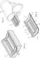
- the method according to the invention comprises the step of laminating first layers 7 of non-cured composite material on the forming tool 8, thus forming a sub-skin 6 having a first surface 6b in contact with the forming tool 8 and a second surface 6a opposite the first surface 6b ( figure 1 ).
- the first layers 7 are laminated with the fibres of the composite material parallel to a common direction, preferably the longitudinal direction of the structural component 1.
- the step of laminating the first layers 7 basically comprises:
- each one of the first layers 7 is laminated according to a direction of its own, which can be different from (namely, not parallel to) the direction of lamination of the other first layers 7.
- sub-skin 6 is part of the skin 4 and is defined by a plurality of layers of composite material that is smaller than the totality of layers making up the skin 4.
- the skin 4 consists of first layers 7 and second layers 10 of composite material, as better explained below.
- the aforementioned totality of layers of the skin 4 exclusively comprises the first layers 7 and the second layers 10 (the latter visible in figure 8 ).
- the method also comprises the steps of:
- the stringers 2 and the ribs 3 are placed on the sub-skin 6 by interposing an adhesive material, which is known per se and is not described in detail.
- the composite material constituting the stringers 2 and the ribs 3 preferably is already cured (pre-cured) and the curing step (applying temperature and pressure) is used to cure the material of the sub-skin 6 and to rigidly fix the stringers 2 and the ribs 3 to it.
- the curing is preferably carried out by inserting the assembly comprising sub-skin 6, stringers 2 and ribs 3 into an autoclave 50, which is schematically shown in figure 5 .
- the method further comprises the steps of:
- This sub-panel 5 is reinforced with stringers 2 and the ribs 3 and, at the same time, has a very small thickness defined by the thickness of the sub-skin 6, which only comprises the first layers 7.
- the sub-skin 6 is relatively thin, for it has the minimum number of layers of composite material deemed to be structurally indispensable.
- the first layers 7 are, for example, two and the second layers 10 are, therefore, eight.
- the step of laminating the first layers 7 comprises laminating at most two layers 7 of non-cured composite material, preferably two layers 7.
- a plurality of forming tools 8 could be used to form the plurality of sub-panels 5 in parallel, thereby reducing forming times.
- the method according to the invention also comprises the steps of:
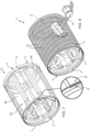
- an internal volume is defined, which is delimited by the set of internal surfaces 6a and (at least partially) houses the central support 11.
- the central support 11 is defined by a sort of spoke system that supports the sub-panels 5 in the area of the internal surface 6a of the relative sub-panels 6.
- the aforesaid internal volume is cylindrical.
- the internal volume could take any shape, dictated by the shape of the sub-panels 5.
- the central support 11, i.e. the spoke system to the different shape of the sub-panels 5 in order to support a pre-component 12 having any shape.
- the sub-panels 5 are placed on the central support 11 and then joined together, so that the respective ribs 3 are circumferentially aligned around the axis A.
- the skin 4 is obtained by laminating the second layers 10 of non-cured composite material on the external surface 12a of the pre-component, so as to define a continuous external over-skin 13 on the pre-component 12 and so as to define the skin 4.
- the skin 4 consists, as specified above, of the first layers 7 and the second layers 10.
- the skin 4 comprises, in particular consists of, the sub-skin 6 and the over-skin 13.
- the method according to the invention comprises the step of:
- the lamination of the second layers 10 on the pre-component 12 is carried out by applying a continuous fibre 14 of composite material on the external surface 12a and, subsequently, by layering the continuous fibre 14 on the external surface 12a.
- Each one of these coatings defines one of the second layers 10, which define, as a whole, the over-skin 13.
- the component 1 is able to withstand high stresses in operation.
- the pre-component 12 itself defines a tool, or a sort of spindle, on which to lay up the second layers 10 and complete the forming of the skin 4.
- the structural component 1 comprises a continuous sub-wall 12a defined by the external surface 12a, namely defined by the union of the external surfaces 6b of the sub-skins 6 of the sub-panels 5 joined to one another.
- the second layers 10 are laminated on the first layers 7 so as to define the over-skin 13 layered on the aforesaid sub-wall 12a.
- the method further comprises the step of:
- this assembly is wrapped in a corresponding vacuum bag 52, inside which a vacuum is applied, and is then inserted into the autoclave 50.
- the stiffened structural component 1 made of a cured composite material is obtained.
- the step of joining comprises overlapping a lateral edge 16 of a first sub-panel 5 and a lateral edge 15 of a second sub-panel 5 adjacent to the first sub-panel 5, as shown in detail in the enlargement of figure 7 .
- a first lateral edge 15 defines a receiving portion, which, in the embodiment shown herein, consists of a longitudinal recess preferably extending along the entire longitudinal extension of the edge 15 and, hence, of the sub-skin 6.
- a second lateral edge 16 defines a coupling portion, which longitudinally extends along the entire longitudinal extension of the edge 16 and, hence, of the sub-skin 6.
- the receiving portion 15 is engaged by the coupling portion 16 ( figure 7 ).
- these sub-panels 5 are placed on the central support 11 so that the edge 16 engages the recess defined by the edge 15 or, rather, so that the edge 16 overlaps the edge 15 (which defines a recess).
- edge 16 of a sub-panel 5 overlaps the edge 15 of the adjacent sub-panel, so that the edge 16 is radially more on the outside than the edge 15.
- the joining between the sub-panels 5 takes place simply by means of a sort of male-female coupling, without the need to provide complicated joining elements that can weigh down the structural component 1 and ensuring the continuity of the lamination surface for the lamination of the over-skin 13.
- an adhesive layer is interposed between the receiving portion 15 and the coupling portion 16.
- the step of joining further includes fixing the receiving portion 15 and the coupling portion 16 to one another by interposing an adhesive layer (not shown) between them.
- the Applicant observed that, thanks to this type of joining, the resistance to an internal stress, for example a variation in the pressure external to component 1 with respect to that internal to it, has significantly improved.
- the lamination of the first layers 7 on the forming tool 8 is carried out by means of a laminating device, for example an automatic machine of the "AFPM” ( “Automated Fibre Placement Machine” ) type, which known per se and not shown herein.
- a laminating device for example an automatic machine of the "AFPM” ( “Automated Fibre Placement Machine” ) type, which known per se and not shown herein.
- the forming tool 8 is moved towards the laminating device by an offset (not shown) equal to the thickness of the set of second layers 10 constituting the over-skin 13.
- the method further comprises the step of moving the forming tool 8 towards the laminating device by an offset equal to the thickness of the set of second layers 10, namely equal to the thickness of the over-skin 13.
- FIGS 11 and 12 show an alternative embodiment of the structural component 1 according to the invention.
- the structural component 1 is defined by a tank, preferably a cylindrical tank, with at least two internal volumes V1, V2 separated by a bulkhead 17.
- the bulkhead 17 is defined by at least some of the ribs 3 of the sub-panels 5 joined together.
- a rib 3 provided with a projecting portion 3a is placed on the surface 6a of the sub-skin 6.
- the projecting portion 3a has a shape that is such as to extend inwards at least up to the space occupied by the axis A once the component 1 is formed.
- the method further comprises the step of placing the ribs 3 of the different sub-panels 5 in respective positions adjacent to one another by means of the steps of placing the ribs 3 and of joining the sub-panels, to define a bulkhead 17 of the structural component 1 formed by the set of ribs 3.
- each rib 3 defines a sector of the bulkhead 17.
- the bulkhead 17 separates the two volumes V1, V2 of the tank.
- the structural component 1 thus obtained has an improved resistance to stresses: as a matter of fact, the second layers 10, namely the over-skin 13, bear the operating loads, whereas the sub-panels 5 and the joints between them only bear the loads exerted by the internal pressure.
- the fact that the second layers 10 are laminated in a continuous fibre 14 allows manufacturers to further increase the resistance to stresses.
- this joining configuration allows for a better resistance to internal stresses deriving from a variation of the pressure external to the component 1 with respect to the internal pressure thereof (as in the case of aircraft fuselages operating at high altitudes or in the case of pressure tanks), since the greater the thrust acting from the inside, the greater the compaction between the receiving portions 15 and the coupling portions 16, also thanks to the adhesive possibly interposed between them.
- the invention allows leads to improvements both from the structural point of view and from the point of view of streamlining and simplifying the process for manufacturing the component 1.
Landscapes
- Engineering & Computer Science (AREA)
- Mechanical Engineering (AREA)
- Chemical & Material Sciences (AREA)
- Composite Materials (AREA)
- Aviation & Aerospace Engineering (AREA)
- Architecture (AREA)
- Civil Engineering (AREA)
- Structural Engineering (AREA)
- Moulding By Coating Moulds (AREA)
- Casting Or Compression Moulding Of Plastics Or The Like (AREA)
Applications Claiming Priority (1)
| Application Number | Priority Date | Filing Date | Title |
|---|---|---|---|
| IT102023000023190A IT202300023190A1 (it) | 2023-11-03 | 2023-11-03 | Metodo per la fabbricazione di un componente strutturale rinforzato in materiale composito e componente strutturale |
Publications (1)
| Publication Number | Publication Date |
|---|---|
| EP4549312A1 true EP4549312A1 (fr) | 2025-05-07 |
Family
ID=89983719
Family Applications (1)
| Application Number | Title | Priority Date | Filing Date |
|---|---|---|---|
| EP24210137.6A Pending EP4549312A1 (fr) | 2023-11-03 | 2024-10-31 | Procédé de fabrication d'un élément de construction rigidifié en matériau composite et élément de construction |
Country Status (5)
| Country | Link |
|---|---|
| US (1) | US20250144898A1 (fr) |
| EP (1) | EP4549312A1 (fr) |
| JP (1) | JP2025078060A (fr) |
| CN (1) | CN119928301A (fr) |
| IT (1) | IT202300023190A1 (fr) |
Families Citing this family (1)
| Publication number | Priority date | Publication date | Assignee | Title |
|---|---|---|---|---|
| KR102845362B1 (ko) * | 2024-01-04 | 2025-08-13 | 동진기업(주) | 테이프 자동화 공급 유닛 |
Citations (2)
| Publication number | Priority date | Publication date | Assignee | Title |
|---|---|---|---|---|
| EP2989001B1 (fr) * | 2013-04-25 | 2020-01-15 | Saab Ab | Procédé de manufacture et plan de sustentation avec une structure composite de revêtement de type caisson de torsion |
| US20230219307A1 (en) * | 2022-01-07 | 2023-07-13 | The Boeing Company | Composite Fuselage Fabrication |
-
2023
- 2023-11-03 IT IT102023000023190A patent/IT202300023190A1/it unknown
-
2024
- 2024-10-30 US US18/931,589 patent/US20250144898A1/en active Pending
- 2024-10-31 EP EP24210137.6A patent/EP4549312A1/fr active Pending
- 2024-11-01 JP JP2024192895A patent/JP2025078060A/ja active Pending
- 2024-11-04 CN CN202411557809.4A patent/CN119928301A/zh active Pending
Patent Citations (2)
| Publication number | Priority date | Publication date | Assignee | Title |
|---|---|---|---|---|
| EP2989001B1 (fr) * | 2013-04-25 | 2020-01-15 | Saab Ab | Procédé de manufacture et plan de sustentation avec une structure composite de revêtement de type caisson de torsion |
| US20230219307A1 (en) * | 2022-01-07 | 2023-07-13 | The Boeing Company | Composite Fuselage Fabrication |
Also Published As
| Publication number | Publication date |
|---|---|
| IT202300023190A1 (it) | 2025-05-03 |
| CN119928301A (zh) | 2025-05-06 |
| JP2025078060A (ja) | 2025-05-19 |
| US20250144898A1 (en) | 2025-05-08 |
Similar Documents
| Publication | Publication Date | Title |
|---|---|---|
| CA2815523C (fr) | Raidisseur de chapeau composite, nappes de pression renforcees de chapeau composite et procedes de fabrication de ceux-ci | |
| EP2301840B1 (fr) | Structure d'aeronef integré de matériau composite | |
| EP2727711B1 (fr) | Remplissage de rayon composite et procédés de formation de celui-ci | |
| US9302759B2 (en) | Flexible truss frame and method of making the same | |
| EP1231046B1 (fr) | Méthode pour la fabrication d'éléments de matériaux composites par technique de co-adhesion | |
| US9284035B2 (en) | Composite tubular-reinforced integrated structural panels with mutually intersecting stiffeners and fabrication processes | |
| AU2011269749B2 (en) | Composite structures having integrated stiffeners and method of making the same | |
| EP2455214B1 (fr) | Procédé pour la fabrication d'un élément d'union pour raccorder des bords des panneaux en sandwich composites | |
| US20250144898A1 (en) | Method for the manufacturing of a stiffened structural component made of composite material and structural component | |
| EP4461517B1 (fr) | Procédé de fabrication d'une structure en forme de caisson en matériau composite pour aéronef | |
| CA3251261A1 (fr) | Méthode de fabrication d’un composant structural raidi fait de matériau composite et composant structural | |
| BR102024022775A2 (pt) | Método para fabricar um elemento estrutural, e, componente estrutural | |
| EP4480683A1 (fr) | Procédé de fabrication d'une structure en forme de caisson en matériau composite pour aéronefs | |
| US20250083792A1 (en) | Circumferential skin joints for aerospace structures, methods of assembling the joints, and methods of manufacturing fuselage members that define the joints | |
| EP4001101A1 (fr) | Fabrication de longerons à segments multiples |
Legal Events
| Date | Code | Title | Description |
|---|---|---|---|
| PUAI | Public reference made under article 153(3) epc to a published international application that has entered the european phase |
Free format text: ORIGINAL CODE: 0009012 |
|
| STAA | Information on the status of an ep patent application or granted ep patent |
Free format text: STATUS: THE APPLICATION HAS BEEN PUBLISHED |
|
| AK | Designated contracting states |
Kind code of ref document: A1 Designated state(s): AL AT BE BG CH CY CZ DE DK EE ES FI FR GB GR HR HU IE IS IT LI LT LU LV MC ME MK MT NL NO PL PT RO RS SE SI SK SM TR |
|
| STAA | Information on the status of an ep patent application or granted ep patent |
Free format text: STATUS: REQUEST FOR EXAMINATION WAS MADE |
|
| 17P | Request for examination filed |
Effective date: 20251021 |
|
| GRAP | Despatch of communication of intention to grant a patent |
Free format text: ORIGINAL CODE: EPIDOSNIGR1 |
|
| STAA | Information on the status of an ep patent application or granted ep patent |
Free format text: STATUS: GRANT OF PATENT IS INTENDED |
|
| RIC1 | Information provided on ipc code assigned before grant |
Ipc: B64C 1/06 20060101AFI20260218BHEP Ipc: B29C 70/32 20060101ALI20260218BHEP Ipc: B29D 99/00 20100101ALI20260218BHEP Ipc: B29C 70/86 20060101ALI20260218BHEP Ipc: B29C 70/44 20060101ALI20260218BHEP Ipc: B29L 31/30 20060101ALN20260218BHEP Ipc: B29L 31/00 20060101ALN20260218BHEP |
|
| INTG | Intention to grant announced |
Effective date: 20260305 |